Is inductor quality a factor in sound quality

Hi Thanks for reading. I’m building a three-way crossover.
Concerning the mid and tweeter filter, I am using a capacitor in series with the drive unit and an inductor across the drive unit to form a second-order filter.
Can I use a cheap ferrite core inductor across the drive unit, or does it have to be a good quality air core, to achieve the best sound quality. My thinking is: Since I will never hear the sound signals that pass through the inductor, not matter what the inductor does to those sound signals, it should not affect the sound coming out of the speakers. Is this true?
Or does the inductor affect the end sound that will come out of the speakers

How can I wire 2 Subwoofers to this Receiver??

I have 1 sub operating using the single Sub Out on the receiver, but am having a hard time figuring out how to get the 2nd sub wired to receive a signal. I have tried to wire the 2nd subwoofer using a 2 channel speaker wire to RCA converter box, but there was a lot of static when I plug everything in... Please help!! And thank you!!


Receiver: Cambridge Audio AXR100

Subwoofers: Klipsch R-120SW

RCA Converter: PAC LP3-2 Pro Series

Extended Bass Shelf versus Quasi Butterworth 5

I've been trying to read more about Quasi Butterworth 5(QB5) ported boxes. I can't seem to find any answers to what a QB5 actually is. I've only read that they are a bit larger than your standard SBB4 type boxes, and tend to have a bit more output around the tuning frequency, causing a knee in the graphs. I understand that an EBS alignment is quite a bit larger than an SBB4 alignment.

What is the difference between an EBS and a QB5 types of ported boxes?
I've always tried to build vented boxes about 20-25% bigger than the manufacture's recommended size because I prefer an increased output at lower frequencies. I often sacrifice the 55-100hz region because I use multiple 8 or 6.5 inch drivers for this.

thanks Brad

Vlog series: The CD revolution: Part 1-3

Part 1:
Login to view embedded media
Part 2 seems to the most interesting.
The CD revolution: Part 2: do all CD players sound the same?

In this video (Pt.2 of 3), I explore two main questions: Can a 30 year old vintage CD player sound as good as a top of the range modern one? And, if we use our CD players as 'transports' (by connecting them to a DAC via their coax digital outputs), will they sound the same as each other, and as good as a modern high-quality transport?

CD Players featured: Vintage - QUAD 67 (from 1993), Philips CD 880 (from 1989), Sony CD 'Walkman' (From 1999)
Modern: Cyrus CDi-XR with PSU XR, Rega Saturn MK3, Pro-ject cd-box-RS2-t with Pre Box RS2 Digital DAC, Philips TAEP 200 (DVD/CD player).
Login to view embedded media
  • Like
Reactions: jotom750

Board/design for powered "active" desktop speakers.

I have a pair of nice, full range 3" Lii Song drivers I'd like to build some cabinets for, and setup as active speakers that can be used as bluetooth and possibly also with RCA inputs. I'm OK with one box having the electronics and wires going to the second one. Looking for decent quality over price, what are some good options to look at? I'm fine with a DIY solution as well.

Here are the drivers, 3" 4 ohm https://www.lii-audio.com/product/o...speakers-desktop-and-bookshelf-solution-al-3/

And these are the cabinets I plan to build for them.

3-inch.jpg

Calibrating a UMIK

All: I have been writing PYTHON code to set up an audio test and have both my internal mic and a UMIK up and running. The UMIK comes with a calibration file, so I am wondering if anyone knows what the spec is to apply the calibration parameters to the incoming audio stream. It must be out there because REW apples it, but I don’t see anything on the MIniDSP site. Thanks, Mike

TDA7294 amplifier lower volume on left channel

Hello All!

I'm playing around with this TDA7294 amplifier board:

https://www.pcbway.com/project/shar..._Amplifier_with_bass_and_treble_499c51bf.html

I've completed the board and hooked it up for testing. It works, but I notice a lower output volume on the left channel compared to the right. It's not a huge variation but noticeable. My electronics knowledge is limited so can anyone suggest what might be causing the difference and what I should try to fix it? Also, is there an easy way to determine the power ratings on the SKP0228 transformer? It puts out 24-0-24. I can't find any information online. Thanks so much!

Attachments

  • PXL_20230407_142850062.jpg
    PXL_20230407_142850062.jpg
    537.3 KB · Views: 172

Best recorded CDs - Best sounding

I'm seeking for very high quality recording CD's (all genre)

I know already that TELARC are doing well, and Sheffield Lab too.

But regarding artists ?

For those who know electronic music genre, you may know that Infected Mushroom is absolutely amazing on high-end sound system. Sphongle either.

Any CD to recommend ?

I'm seeking for FEELING, you know what i mean 😎

Pro-Ject RS Amp Box with upgraded Power Supply

For Sale: Pro-Ject RS Amp Box Amplifier. Uses a pair of Hypex UCD180 amp with two 6922 tubes as a buffer. The +/-48V @ 2.5A stock power supply was replaced with a +/-48V @ 5A SMPS.

Sounds great and takes Single Ended as well as Balanced inputs.

How's $500 + Ship?

Attachments

  • PXL_20220426_001343164.jpg
    PXL_20220426_001343164.jpg
    278.3 KB · Views: 473
  • PXL_20220426_001354214.jpg
    PXL_20220426_001354214.jpg
    240.7 KB · Views: 388
  • PXL_20220426_001358225.jpg
    PXL_20220426_001358225.jpg
    209.8 KB · Views: 493
  • PXL_20220426_011521111.jpg
    PXL_20220426_011521111.jpg
    306.8 KB · Views: 901

Made myself a EL84 PP Tubelab Clone

I have been working with my El 84pp, Tubelab clone for some time now. I have Hammond output transformers and chokes for my project. For about twenty years ago I bought a transformer for 250v and 6,3v. Made for 220v, and I have 235v in my outlets, so I had to get rid og 15v. If not i got 7v on the heathers...I solve the problem by using av 235 to 220v transformer! i series with the IEC-socket. Using 6P14P-EV and ECC81 from the late 50-s.Have been playing cd-s from a Cambridge player, through a Topping Dac, to the el 84 Tubelab Clone and in to my Klipsch RP 160M. I just love the sound! Bass is good, midrange are great..and so are the treble
El 84 pp.jpg
..I put some more pictures out tomorrow

UNSET is coming?

UNSET is coming......

I have mentioned these words a few times in passing, but the truth is that UNSET only existed in LTspice at the time. The simulation showed unreal performance, but that is often the case with vacuum tube simulations, especially those where the tube is not connected up in a conventional manner.

This was the case for about a year. I have too much on my plate to effectively handle right now, so the simulation, along with several others sat in my PC undisturbed for a long time. Late last year I put together a test board for a push pull amp that used UNSET technology in the output stages only. It did work rather well, and I planned to pursue a follow up design, but the need to redesign the TSE board popped up, which is not yet finished. The boards are done, but all the documentation is still a mess.

About 3 weeks ago my wife started exhibiting heart attack / stroke symptoms, but refused to go to a doctor until bad stuff happened. There were good days and bad days for two weeks, which required my full time attention. During the evening of one of the good days we were both at this computer ordering some stuff for a baby shower when she said that she didn't feel well and wanted to go upstairs. Before we got to the stairwell, she passed out and dropped to the floor. I managed to get her upstairs, out to the car, and to the ER. They stabilized her and eventually figured out what the cause was, but this was the beginning of 4 days in the hospital and some full time watchfulness from me once she was home.

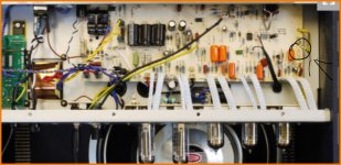
During the 4 days in the hospital she was sleeping most of the time so I fetched my laptop and did what I often did with a few days of idle time.....took one of my best simulations and made it into a PC board.

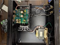
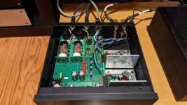
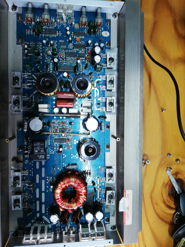
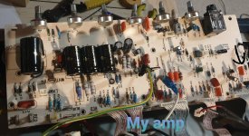
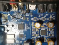
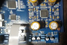
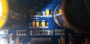
UNSET the simulation became UNSET the test board. it was a hurried up layout, many parts didn't fit right and a few were just left out by mistake. Over the past few days I populated the board with the exact parts from the simulation except where I didn't have the right part, I stuck in whatever I had. What were the chances that this would work? Would it blow up in my face? Am I going to stick expensive tubes into this thing? No way........

So, briefly, what is UNSET?

A SET is a Single Ended Triode amplifier. The SSE, TSE, and new TSE-II amps are examples of this, but the SSE often uses pentode tubes wired as triodes. This works, the pentode takes on triode like qualities with the associated triode disadvantages, most notably the inability to pull its plate down near the cathode voltage thus limiting the available power output. Another issue that needs to be overcome is the screen grid voltage limitations of most TV sweep tubes. Wire them as a triode, and most will eventually blow up when left alone idling which is worse case for a class A amp (maximum dissipation). The tube doesn't know if it's pentode, UL, or triode connected when it's idling, it just gets a constant voltage on it's elements, and if the screen grid is significantly above it's maximum spec, there is a risk that it will blow up (some will, some won't, but most will if left long enough).

What if there was a better way?

I have been searching for this better way for nearly 10 years. I experimented with screen drive, dual drive, and even built my GUT (Grand Unified Theory) board which had the ability to drive every electrode independently in either phase, except the plate and heater. Several toasted (and two exploded) tubes and nearly 10 years later, I arrived at a new topology that I can't find anywhere it recorded vacuum tube history.....yes, there are several close similarities, but this is truly unique.

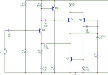
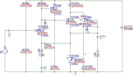
I called this topology the Composite Electron Device for lack of a better name, since it is a composite of a vacuum tube pentode, a mosfet, and a hand full of discrete parts to create triode like curves. The screen grid specs are not violated, so that nearly any pentode will work with appropriate component values. Note that this statement is still based primarily on simulations, with some limited actual tube testing.

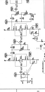
I will not reveal the full schematic just yet, but it is coming.........

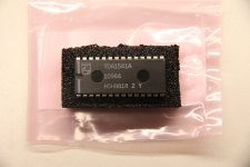
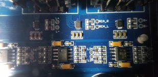
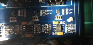
The UNSET is an amplifier design that uses CED topology for its driver and output stages. A small CED is built with a high Gm pentode for the input / driver stage. I used a 6EJ7 / EF184 in the simulation, but stuck a $1 tube in the test board.

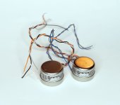
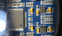
The output stage uses an identical circuit built with bigger parts. I laid out the board such that several popular octal tubes could be used, but messed this section up pretty bad. I wired it up to use an unloved and unwanted octal sweep tube that I have LOTS of.....A popular tube seller sold me over 100 of them for under 50 cents each!

After finding my mistake with a backwards zener diode, I was really surprised by what happened next.........

For Sale Philips TDA1541A DAC D/A Converter IC Genuine Original New

New (NOS) genuine original Philips TDA1541A DAC D/A Converter IC. 28-pin DIP. Purchased from a US distributor many years ago as Big Sky Audio, LLP was an authorized ADCOM & Parasound service center. $70 shipped.

Sold "as-is" and no warranty is expressed or implied. No returns or refunds. Sells and ships to USA residents only.

Attachments

  • IMG_4575.JPG
    IMG_4575.JPG
    233.7 KB · Views: 121

HPA with constant Vce output stage

I don`t know who is author of this scheme, probably Sivasankar Chander 2008. Was posted here on diyaudio long time ago and probably was archived. Accidentally came across on this in my archive. What do you think? Constant Vce kills Miller effect and leads to significantly decrease non-linearity and intermodulation distortions.
High side transistor`s TDP just 75 mW => it`s possible to use very fast, low capacitance and high beta TO-92 devices. Low side device - something in TO-126 because of 700 mW TDP.
Looks better than simple 3-transistors design with barely the same BOM, posted here 3 years ago.

Attachments

  • scheme.jpg
    scheme.jpg
    47.9 KB · Views: 216
  • ratings.jpg
    ratings.jpg
    89.1 KB · Views: 214

PGA2311 as input channel selector, without use any relay...

Hi, everyone.

After reading many posts and articles on diyAudio, I became unbearably curious and just signed up and now I'm writing a post here.
I don't have much knowledge about digital or analog electronic circuits, so even if my question is basically wrong or stupid, I appreciate your understanding.


I am designing an all-in-one system with an input channel selector, a preamplifier, and a few more features using the TDA7292, PGA2311, and ATmega328PB processor.

At first, I tried to use the method of selecting the line in channel using the signal relay and controlling the volume using the analog potentiometer of Alps Alpine. All systems except volume control are controlled by the main processor.


But I soon realized that it (Alps' analog potentiometer) isn't very good in terms of cost, production, and quality, and now I'm trying to use TI's PGA2311 to control the line in volume.
One PGA2311 chipset is responsible for one line input, and multiple PGA2311 chipsets are installed on the PCB as many as the desired number of line inputs.
The idea was that when switching line input modes, one PGA2311 chipset would slowly attenuate the output to 0%, while the other PGA2311 chipset would slowly increase the volume of the other line input, resulting in what would appear to the user as a smooth transition between the line inputs.
Since the PGA2311 is used as a line input selector, the Lout+, Lout-, Rout+, and Rout- pins of each chip are shared as one. (The audio grounds of L and R are separated to use differential line input.)

Because the PGA2311 can mute line inputs, I thought that using multiple PGA2311s would allow me to control as many line inputs as I wanted, so I removed the line input selector circuit(using signal relays) that I had painstakingly designed at first.


However, while looking for some resources on Google to program the PGA2311, I found a line input channel selector designed by someone. The channel selector that I found was still using a relay to switch the line input despite having a built-in PGA2311 chip.

Suddenly, I became anxious that the direction I was designing might be wrong.
So I referred to many posts and searched for many products sold on the Internet. but what they have in common is that they use a relay as an input channel selector.


This is where my question arose: While PGA2311 has a MUTE function, but why use a relay to configure the input channel selector?
Or is my idea fine in theory and just a matter of personal preference?

The first thing I can guess is... the cost problem of the PGA2311, which I am most comfortable with.
Since the number of line inputs is about 3, which is not that many, I think it is worth investing in 3 PGA2311 chips if it is simply a matter of cost.
Also signal relays use physical contacts, their switching speed is slow, and they can wear out or oxidize, so I don't want to use them if possible.

But I think I may be wrong.
Are there other issues besides cost? I think there could be other reasons such as interference by electrical signals, problems with matching impedance, problems with programming pins, etc...

Please let me know your opinion.

Thank you.

This a new one for me...

Yamaha RX v3000...starts clicking rapidly when I plug in into the wall socket...without even pressing the power button. However, two large resistors on the F-Amp board get extremely hot rather quickly. How does energy get to the F-Amp board when the receiver isn't even powered on??? Guess it's an obvious short somewhere in the circuit...but I've not seen this happen before....when the unit is powered off. Don't even know where top begin to look...

Ground Zero recommended port size- second opinion please!

Hi there.

I'm building a subwoofer cabinet for the Ground Zero GZHW 30XSPL-D2.

This is really bugging me now- I'm looking at the recommended port sizing as follows, from the user manual:

Bassreflex / vented 90 Liter netto / 3.18 cu.ft. net
Recommended enclosure Port (dimensions) 40 x 250 mm / 1.57 x 9.84”
Portlänge / port length 257 mm / 10.11” F3 (-3 dB) 25 Hz

This gives a 100cm2 port area for a 90 litre cabinet. This seems to me to be very small! All the built cabinets I can find have port areas of 150+cm2.

Can this recommendation possibly be a good one? I'd rather trust the recommendation if it's credible, but really scratching my head about it.


Hornresp shows a peak particle velocity of 2.8m/s @1 watt. And 125m/s at program wattage.

Thanks!

Altec Model 19 Clone Help

I need some help tuning the box for my Altec model 19 clones.
36607956-C0A8-4B87-9D04-1B327E019791.jpeg


C0A87383-4413-49FC-B98C-BD419524DF7A.jpeg


The speakers are built into an existing media room cabinet and use Great Plains Audio drivers. GPA recommends 8.8 ft.³ cabinet volume for the 416 drivers. I built the cabinets with 9.08 ft.³ volume to give myself a room for error. Dampening material is No-Rez, which Danny told me should have almost zero influence on the cabinet volume. The port is 6 inches diameter and 6.91 inches in length per the Precision Port calculator For a tuning frequency of 29 Hz, as recommended by GPA. Note, the baffled side of the flared port is fabricated from wood, but it is identical dimensions as the plastic PP unit.

Using Dayton Audio DATS V3, I am measuring a F(b) of 26.6 Hz. Working backwards using the PP calculator for this port at this frequency generates a 10.5 ft.³ volume cabinet. Inserting half cubic foot of material in the speaker to reduce volume results in zero change in frequency.

E7C6D259-BB72-483E-A061-B9D97F9F3DA3.jpeg

What am I missing? The volume may be off by a 0.2 ft.³, but I’m not off by 1.5 ft.³.
ED564D24-156F-4D63-9620-E6A4DC05C14C.jpeg

NAD 3130 Difficult Repair

Hey folks,

I have a NAD 3130 that I just cannot get working properly. It smoked randomly one day, I opened it up and found that the output devices on the left channel had shorted out, so I ordered a new MJ2955 and 2N3055 on eBay. I replaced Q413 and Q 411 which were both shorted, and replaced R459 which was burnt.

I then turned it on with a dim bulb tester - and got a very bright light!

Turned it off and found that Q407 was leaky/partially shorted - so i decided to replace that and also Q409 for good measure. I also had spares for Q405, Q401 and Q403 so opted to replace those too even though they measured fine. Additionally i replaced C 421 which looked ever so slightly bulged.

Turned it on again with dim bulb tester, this time It switched on with a nice green light on the front, but that light quickly faded out and the dim bulb began to light up - no where near as bright as before but still definitely too bright. If i leave it in this state, Q417 and Q415 heat up to around 50c in 5 minutes and seem to stabilise there. As this happens, the voltage on them goes from about 20v to 30v, and the bulb tester goes dimmer and dimmer. Eventually the green light on the front switches back on. The center voltage adj pots seem to be dead as turning them does nothing, however both channels are reading around 35mv on outputs - not ideal but definitely not the cause of my problem. The idling current is 0.2mv (!!!) on the left (bad) channel, and about 5mv on the right channel.

I have tested EVERY resistor on the left channel against the right - they all read the same values. I have performed diode meter checks across all capacitors - no shorts. I've checked the two zener diodes - all fine. Can anyone help me figure out what I've missed? I feel like I'm so close but there's just one thing left I can't find.

Amazed by CHP-70 gen2

This driver seems to be the most i like in the Mark audio family. Amazing bass from such a small driver , and the reduced emission on highs its perfect for a Natural vocals to my 60's ears.

Which larger paper driver would be quite similar in tone and vocals Natural sound to those tiny jewels? CHP 90 or alpair 10P?
Thanxs ,would love to try One of those in my larger TL
  • Like
Reactions: GM and mikejennens

Remote low voltage capacitor connection advice

I want to make a non permanent connection to an analogue board on a modified analogue board that now have no room for on board additional capacitors. As I may need to take the removable board off I want to connect with a fly lead that can be disconneced. I will use low impedance cable to the cap and sheild very well using around 16AG or possible 20 what are good small diameter cable. I have looked at some cheap bullets I have and they are horrible. The small spade might work and I cant see to find any nice, copper or nice connectors that are small. Are there any nice high quality small diameter connectors I cant seem to see any ? I can obviously use cheap brass tin plated but be great to fins some nice ones

Repairing Linn Axis Motor Drive Amplifier

Hi all,
As i said if I managed to fix the Axis motor board I would post accordingly, so here goes.
FIRST A WARNING, the motor board is connected directly to the mains supply so will need VERY careful handling if you are not to give yourself some unpleasant surprises.
Remember electricity will not give you a second chance and until the fuse blows Battersea Power Station or its equivalent is sitting at the other end of the cable. Also any test equipment that is connected to this circuit will be "live", so earthed equipment (scopes etc) MUST either have the earth wire lifted from the plugtop or not used at all. If you have any doubts about your capabilities do not work on this board.
There is a way around it and that is to use an isolating transormer and then you can earth the secondary but it is somewhat a costly exercise.
Also remember the "one hand in the trouser/skirt pocket" rule when using test equipment to measure voltages etc
So..........
My unit would not turn the motor, so first check was voltages on the bridge rectifier, about 320V DC, correct, and also across C5 about 12-13VDC, correct, so I initially suspected the two main coupling capacitors C8/C9, which were removed, measured (both read 33µF, correct value) and substituted for good measure. No improvement of course.
I then turned my attention to the other other electrolytic capacitors C6,C11,C16,and C17. These are all 22µF/63V capacitors and they all measured very low capacity generally 5-6µF. Replacement appeared to effect a total cure, however I was somewhat puzzled when I looked at the sine wave feeding the motor to see it drop in level and the motor stop rotating.
I then remembered Linn's penchant for reducing motor volts so it just turns the platter, the motor relying on the inertia of the platter to keep the motor rotating and vice versa. Once assembled totally all worked fine, with speed being fractionally fast to overcome stylus drag etc, however the speed adjust controls are available through the base of the case if required.
I reckon that the electrolytic capacitors dried out over the years 'til they reached the point of no return and I think that the best solution is to replace them all with new.
Hope this helps you all out there but if you have any further problems send me a pm with phone nr etc and I will try to assist

John Caswell

turn your audio amplifier into power generator (manual)

Hello!

I know many of you are builder. I've tried this technic and it worked for me. Feel free to make it. Here is the instruction. Ask here any question while building 🙂.

Best Regards!

Przemek Jagielski.

Attachments

  • Poll Poll
Take the THD challenge!

I can hear distortion down to:

  • 1%

    Votes: 7 14.3%
  • 0.1%

    Votes: 30 61.2%
  • 0.01%

    Votes: 10 20.4%
  • 0.001%

    Votes: 2 4.1%

How much distortion can you hear? Take this two-minute test to find out.

The attached file contains four frequency sweeps. Each sweep consists of a fundamental from 100-500Hz and a seventh harmonic at 1%, 0.1%, 0.01%, and 0.001% respectively.

The test should be made with good speakers or headphones (computer speakers may not be able to reproduce the fundamental).

I made the harmonic easy to detect by switching it on and off at a 1Hz rate and putting it in the frequency range where the ear is sensitive.
Ed

Attachments

Mental specifics of transformer winding

I find designing and winding transformers as a unique job, in a sense that it requires a specific mindset. Depending on the severity of requirements on your design, you will need a lot of dedication into practice, reading, experimenting, trial and error. Audio transformer design requires your attention to be very watchful on important details and are less tolerant to errors. Building one needs a considerable amount of concentration and dedication.
In the beginning, one can also face many practical problems, for example figuring out the best equipment for your machine and building the right custom tools for your job.

1682446037174.png


If you are also a winder, how do you find this type of work for you? Is winding transformer a challenging job for you? Why? What difficulties did you mostly face? What were your biggest winding mistakes?
  • Like
Reactions: Jnouw

The customer is always right.

I sold a model railway dcc digital controller.
The buyer got in touch saying it didnt work right.
If he goes into "speed and control" in the menu it allows loco to move but any keys just flip direction but dont turn on lights or sound.
I told him that to do sound he has to go into a different menu function.
He told me that his previous gaugemaster controller worked better.
Next thing I know he is doing a return on it.

So i had a look at it and he is absolutely right, its a nuisance having to go to a different menu to change the sound/lights.
So in the software I hooked into keys 0 to 8 and made them play sounds/lights if pressed.
It took 15 minutes to change the software.

While he was right it was a little unfair comparing my system to the gaugemaster one as its 5 times the price.
Its the usual "mini" syndrome where they buyer wants to buy a rolls royce but at mini prices.
If he had waited I could have fixed this for him but now he is blocked from buying due to fast return and will have to pay many times what he paid for mine.

SET amp with 89db speakers, bi-amping?

I know that similar questions have been up before but I do have an extra question that I have not seen when I did a search so I decided to create a new thread.

I used to have a pair of Kef Q5 speakers paired with a Marantz reciever. I recently built a really good pair of speakers, a Troels Gravesend design called Revelator 851 which would be like 20 times the price of the Q5s if sold in a store. I also upgraded my Marantz reciever to a Vincent SA-T8 tube preamp and a Classé solid state power amp that I bought from the used market. My new setup sound awesome compared to my old system except from one thing. It sound way too clinical. I love the details, the soundstage ect, but really miss the warmth from my old system. So I was thinking of perhaps bringing that warmth back into my system by building a pair of SET monoblocks instead of the solid state power amp I have now. I know SET amp are known for their warm sound.

The new speakers have 89db sensitivity and I do not want to change speakers. Not ideally for a SET amp, I know. How much power do I need ideally? And if I bi-amp the speakers and drive the bass driver with a pair of Hypex class D amps, and just run the SET amp for M and T, will that help? I know that a lot of sensitive speakers are horn speakers so perhaps it's the tweeter that is the culprit? I am a total novice when it comes to tube gear. I know that Stephe that runs the Skunkie Designs Electronics on Youtube are going to make a build series of a pair of KT120 monoblocks that will output around 15W single ended. If they turn out good I might consider them as a project.

Room size is roughly 4*4 meters. A little less. I do want to be able to play somewhat loud.

So:
1. How much power do I need?
2. Will bi-amping with Class D on woofer help to relieve a SET amp?
3. Can a push pull amp deliver the same warmth as a SET amp if I need to go that route?

Many thanks in advance
/Magnus

Musical Fidelity Supercharger

I have always wondered if anyone had made a DIY amp that performs in the same way as the MF Supercharger or if there are any schematics out there. I can't seem to find any.

"The Supercharger 550K uses the latest in low distortion circuitry in a bridged configuration which delivers 550 watts rms. The Supercharger 550K is designed to increase the dynamic range of an existing lower powered amplifier (from 50 watts to 200 watts) to 550 watts. The dynamic range will increase by up to 10dB."

https://www.musicalfidelity.com/uploads/manuals/English/supercharger_550K_english.pdf

I assume (but may be completely wrong) that the OUTs from your "existing" amplifier go IN to the supercharger which uses some kind of Hi-Level to RCA converter circuitry to accept the hi-level input.

If it is that easy I am surprised that it has not been more commonplace or is it that you may end up with a result that is a dogs dinner?

tube amps blow fuse?

Hi

First post! I have several audio tube amps that, when i power them on, they blow out their fuse. They've all worked fine for some time, and previously I was able to meet with a knowledgable person who did some quick cleaning and adjustment and they worked right away. But they're not working again! what are some quick steps i can do to try to diagnose and/or fix them?

Thanks for any help and advice
-Neal

Mid bass sub for slam and impact?

Hi all,

Anyone running primary subs just for infrasonic and subbass frequencies but then run other subs just for mid-bass for slam, impact and just higher SPL up there? Thinking below 20hz is infrasonic, 20hz to 40hz is sub-bass, and 50hz and up basically would be the mid and upper bass as a reference for discussion.

I'm happy with my current subs, which do 18hz to 50hz well. But I'm thinking of building two smaller tower subs to do 50hz to 100hz with room to spare. Was considering a dual driver setup, maybe 12" drivers with ok-ish xmax wired in parallel to be 4ohms to an amp. This would mostly be for fun to increase the pop/clack/boom that my larger subs do not have, they do the rolling thunder thing.

Sealed vs bass relfex for this? My other subs are bass reflex. I think I could get away with either sealed or bass relfex no problem. If reflex I'm thinking a tuning frequency on the port of 40~45hz to have all that extra SPL and limit xmax in two zones that are important to settle.

I'm also thinking one amp, two channels, to handle two of these as a pair (left & right) but could also go individual amp for each.

GRS 12PT-8 (two of these) wired for 4ohm and fed 450 watts of signal. 4 feet^3 and 45hz tuning. Will primarily drive from 50hz to 100hz+ and roll the rest off.

Dual GRS 12PT-8 40hz Tuning Midbass.jpg


Xmax on the above:

Dual GRS 12PT-8 40hz Tuning xmax limits.jpg


Air velocity is in check, if I use a 3" by 14.75" slot port (generalized).

Thinking 36" tall, x 16" wide, x 17.75" deep after drivers, bracing, double baffle, port, 4 feet^3 internal net volume, maybe a bit more depending on how bracing goes. Slot port with 3" by 14.75" entrance/exits, around 10 inches long to be nearly that 45hz~40hz tuning frequency.

Anyone running subs for subbass and others for mid-bass? Do they integrate well? Any tips?

Very best,

Half channels from Anthem MRX 700 receiver at low volume. How to troubleshoot/fix?

Hi everyone, thanks for reading. I have an anthem MRX 700 receiver which I have used for years. Recently, I noticed the volume for my front right, center, back left, and surround left channels were at a much lower volume (not distorted or entirely silent just ~18db lower than the rest). I'm trying to troubleshoot this and see if it is fixable myself since I dont have the opportunity to replace it or send it in for official service right now. I do have some experience in electrical engineering so hopefully that will be possible. I don't have a service manual unfortunately(let me know if you do please!). I've done the basic troubleshooting (swapping cables/speakers/outputs) and have narrowed down the issue to the receiver itself. The channel outputs look clean at the connection. I took off the outer case and can see some corrosion around the hdmi board but nothing else. I did notice that the channels in question are physically in a line next to each other at least for part of the amp board near the transistors as well as on the preamp board and bus. That can be seen here:

svp31W9.jpg

ljaMVJW.jpg


voltage output for each channel with no audio is 0.029V. when doing noise output for level calibration FR goes up to 0.7V SR goes up to 0.15V BSR goes up to 0.15V as well, on the low volume speakers voltage increases to 0.039 on each when noise is output to their channels. connection from the analog board to the amp shows 0.024V on the pre signal for the channel with noise 0v otherwise, same with the connection from analog board to pre-amp.

Any idea what would be some good steps to potentially troubleshoot or fix this? Thank you again!

Cheap subwoofer project?

Hey everyone, first time posting on here after a year or two of lurking and trying to take it all in.

I'm an audio enthusiast but have thus far only ever collected IEMs. I own several pairs, my current endgame being a wonderful set of Unique Melody MEST MKIIs.

Speaker-wise, I've been rocking the same pair of KRK Rokit G3s since forever, and I've been meaning to eventually build my own system. I love high efficiency, large multi ways. Yearning for one of those monstruous ones rocking 18" woofers... But ehhh, budget constraints.

Anyway. Was at a flee market yesterday and scored a pair of mint condition Pioneer Prologue 4 bookshelf for a whooping.. 15€.

9c6db9d5481781fd60ea607758dc.jpg


Plugged them on a cheap bluetooth amp to test them out, and they sound really nice. Full bodied, engagin and detailed, to my surprise. A bit spicy in the treble region, but nothing that can't be fixed. The only thing is, they absolutely and utterly lack any sort of bass impact, as I was expecting from these 8" woofers. These are sealed cabinets and were obviously not designed to rock the house.

I'm thinking of using those as part of a cheap-system to quench my thirst for new audio gear for a little while, as I think they look pretty awesome.

I would want to add a DIY subwoofer to the set, but I honestly don't know where to start looking. I just need that extra oomph and bass details. I'd build the cabinet myself and would like to keep the cost to a minimum. Looking for the best bang for my buck here, because I'll still need to sink some €s into an amp afterward.

Any driver/design recommendations is more than welcome, thanks in advance!
  • Like
Reactions: GM

rockwool fun

Sarcastically said ^. I's there a best / easiest way to also do ceiling and walls inside to further isolate noise? It might be good to cut 5" holes and get stuff blown in for the walls instead? The ceiling, tedious hand filling might be the only way, what do you think? Without ruining the existing wall board, keeping it intact. The idea is to double the existing 3/4" board along with adding wool, strictly for keeping unwanted sounds out and wanted sounds in. The partitions are all interior.

Attachments

  • 20230426_060607[6473].jpg
    20230426_060607[6473].jpg
    356 KB · Views: 95

Favorite Horn/CD Combos

I have gone through many horns and compression drivers (CDs) over the last few years. Currently listening to the JBL 2380 horns driven by JBL 2445J drivers with the titanium ribbed diaphragms. Using a passive crossover around 750 Hz with 4th order acoustical slopes to a JBL2226 15" woofer, and FIR correction (amplitude and phase), the sound is just absolutely stunning. The speakers disappear, and you are placed in the recording space, whether it be a studio, concert hall, or church. When you turn it up, it just gets bigger and bigger and bigger.

Now, the 2380/2445 is a decidedly old-school combo, and nothing wrong with that if it works. I have also tried the BMS 4590 dual-diaphragm driver with the 2380 and while the sound is more refined--that last octave of the 2445 titanium diaphragm is a roller coaster--and yet, it does not have the magic of the 2380/2445 combo, where it feels like instruments are being played by real people with a palpable sense of touch. Clearly, there is something to be said about combining the right driver and with the right horn.

There are some complaints about the 2380 on this and other forums, it being a horn with a diffraction slot, which takes pattern control to 16 kHz. I personally do not find anything grossly offending about it. In fact, it sounds quite delightful after proper EQ. I am not blasting it at ear splitting levels.

I've heard people recommend newer horns from 18sound and others on threads here. What combinations of compression drivers (CDs) and horns have people found to work for them? I am especially interested in experiences with newer horn/CD combos.

Pandemic Food

Like many others, my wife and I stocked up on foods we consume regularly. Peanut Butter being one of them. We buy the type that is not homogenized with trans-fats so it needs to be mixed by hand before eating.

The problem I've encountered with this 2-3 year old peanut butter is that the separation is so complete that the bottom has completely solidified rendering mixing by hand almost impossible.

I have a case of the stuff and was thinking of bringing it to a paint store and have them shake it up with their paint shakers.

low distortion, wide bandwidth pro 15" and 18" drivers

Apologies in advance for starting what is more or less one of those "what is the best..." threads, but...

I'm looking for candidates to be used in the woofer section of a dipole speaker I will build, with the emphasis on low distortion. This will not be used in the lowest band in the system, and covers about 80Hz-500Hz. I am looking for either a 15" or 18" driver, preferably with an open frame. If possible, I would prefer a single pole vent over the multiple smaller motor vents that cause turbulence and noise. Since the motor is "out in the open" the noise can't be suppressed easily. Because of the 80Hz cutoff, I don't need high Xmax and high Qts isn't required either. I would prefer to have high sensitivity, e.g. 95dB/W or greater, and an 8 Ohm nominal driver for ease of driving it and bridging an amp into the load if necessary. Since the band should go up to around 500Hz, low inductance is important, and this is another knock on specialized "subwoofer" type drivers. Finally, I need to be able to purchase the driver from a US distributor, and this eliminates some EU/AUS brands.

This rules out some candidates. For example, I would consider the AE Speakers dipole or IBHT lines of drivers, but they are more along the "subwoofer" line with very low Fs, higher Xmax, and lower sensitivity.

I have been using the Eminence Deltalite 2515 and it seems to meet these requirements. It's also very affordable.

Another candidate I am interested in are the JBL 2268H/2268HPL 18" woofers. There is a JBL tech note showing very low distortion operation above 50Hz at 115dB SPL (not sure in what kind of enclosure, etc.) and the frame is relatively open. It seems very promising.

What other drivers should I be considering?
  • Like
Reactions: DblAA

PPI remote circuit turn-on help.

I have a PPI 2075AM on the bench, nothing is shorted as far as large devices on heat sink. Upon applying power to remote, there is NO IDLE and amplifier’s power supply doesn’t power up.

I am using the partial schematic provided by Perry in another thread, seems pretty similar. Q65 which is a MPSA56 and has is 121mv on collector. I have to inject 14vdc to the Q65’s collector pin in order to get amplifier to actually power up and 3525 to produce outputs on pins 11 & 14. Below are some reading if needed.

I am using 14.4vdc.

3525
1) 2.56v
2) 4.56v
3) 0.017v
4) 0.033v
5) 2.04v
6) 3.67v
7) 2v
8) 4.83v
9) 5.96v
10) 0
11) 0.014v
12) 0
13) 0.121 (this is the 121mv from Q65’s Collector pin)
14) 0.014v
15) 14.24v
16) 5.1v

Q65 MPS56
E) 14.4v B) 14.2v C) 0.121

I tested several 06/56 in that circuit and tested good, no leaks; confused as why Q65’s collector pin is not 14v.

This amplifier was damaged when the remote wire touched ground, in case that helps. Thanks for any input or advice.

Outdoor sub

Looking to build four 18” permanent outdoor subs. They will be installed in a weatherproof cabinet with doors under an overhang. They need to be 8 ohms with waterproof cones. I prefer bass reflex enclosures. Box size and weight is not an issue within reason. They will be music only so I was thinking flat to 40hertz. Budget is around 350 per driver or preferably less. Sound quality is the priority. I was thinking something from B&C, Lavoce, PRV or others. Any suggestions on driver and box design would be great.

Project 30 2 way 100Hz and up

The main purpose was to build an active 2 ways "satellites" to cover frequencies from 100 Hz and up as I have two sub woofers located in corners. I use FusionAmp 503 to power the system.
The cabinet dimensions are 260 x 440 x 224 mm and is made of 18 mm birch plywood. The front plate consist of 2 layers of plywood chamfered on 30 mm at 45°.
One layer of 2 mm bitumen plus one layer of 15 mm felt and melamine foam are placed inside.
Drivers are the new Purifi PT6.5W04 NFA01 (to gain 1.7 dB efficiency) and the Bliesma T34B tweeter mounted on "Pida (Petr Kocourek)" OSWG waveguide
To much of my surprise, I received the new Purifi drivers with serial numbers 00001 and 0002 !


Measurements of each drivers have been taken from +/- 180° both horizontally and vertically in 5° step. I did use VitiuxCAD to simulate the corrections needed.
Final design (for the time being...) was acoustic LR4 at 100 Hz and 1.25 kHz
emphasis on Power response (decreasing slope of 1 dB/octave and in room response along with listening windows


Here are untouched real measurements taken and imported in VituixCAD for presentation. The 2.5 dB bump at about 1.2 kHz is introduced to correct the LR4. I think that power response, DI, in room response and listening windows are well behaved.


We can see the effect of LR4 crossover effect on the vertical polar response by the way (but still a 30° freedom around the crossover region though.


Distortion is not bad either both at 90 dB_1m or even at 100 dB_1m


And now what about the sound ?
It's always difficult to stay objective after having spent weeks on this project but I find the sound at the same time soft and precise with great dynamic when necessary. I'm particularly impressed by the Bliesma T34B in Pida waveguide which can bring very high level with limited distortion as low as 1 kHz.


It's time now to enjoy listening to music on my new system for a while...

Attachments

  • P30.jpg
    P30.jpg
    398.7 KB · Views: 1,792
  • P30 rev 1_1.jpg
    P30 rev 1_1.jpg
    644 KB · Views: 1,391
  • P30 rev 1_2.jpg
    P30 rev 1_2.jpg
    311.8 KB · Views: 1,176
  • 90 dB 1m distorson.jpg
    90 dB 1m distorson.jpg
    496 KB · Views: 285
  • 100 dB 1m distorson.jpg
    100 dB 1m distorson.jpg
    579.6 KB · Views: 293

Noise floor in Fender Blues Jr

I'm "bettering" my Fender blues Jr. So far I've changed my Filter Capacitors, Coupling Caps, Tone Stack values, and Plate resistors with better quality components.
The difference is massive! The sound is full and rich with a lot more pleasent low end.

The next thing to tackle is some high end noise floor hiss. It's nothing particularly strong but it is definitely when I play very lightly.
I'm considering changing V1 from a 12AX7 (100% Gain) to a TAD 5751 (70% Gain).

Rat Valves also removed the *R1-1M resistor (*R2 is a 10k and then it goes to *V1). Would this benfit the circuit in any way? Lower hiss?
If not should i replace them with some better low noise resistors?

My circuit board is the third image.

Attachments

  • 20230311_204342.jpg
    20230311_204342.jpg
    201.5 KB · Views: 259
  • 20230311_203841.jpg
    20230311_203841.jpg
    227 KB · Views: 196
  • 20230311_233550.jpg
    20230311_233550.jpg
    361 KB · Views: 212

Allen Wright inspired world class DIY balanced tube HiFi preamp kit

Allen Wright RTP3C inspired world class DIY balanced tube HiFi preamp kit.

I think this preamp is seen as one of the best balanced tube preamps in the world. The set consists of 2 fully balanced line stages without RIAA, with integrated SuperReg type PSU´s, which are supplies with a Constant Current Source, followed by an advanced shunt regulator.

The pair is delivered as 2 assembled PCBs, without tubes, including full documentation on CD and including Allen Wrights book ”Building tube preamps”. On the pictures you will see that a few parts are missing on one of the PCBs, that is because they were used for a mains filter, that didn´t have a positive influence on the sound, and therefore is bypassed.

They original amp has an L-C PSU configuration that is quite hard to work with, so this design has several integrated regulators in a more conventional design. The amp can be build as one double decker or with a separate box for transformers. A full set of Toroidy transformers for a dual mono build is included, consisting of the following special made and over dimensioned Toroidy audiograde pottet toroid transformers: 2x15v - 100VA, 2x12v - 50VA, 2x20v - 10VA, 2x24v - 10VA og 2x250v - 100VA.

I will only sell the complete package, and it is only recommended for an experienced DIY´er.

I have bought the PCB´s as prebuilt and tested, but have never myself had power on them. You will need 5 pairs of ECC88/E88CC, PCC88/PCC189, 6922, or equivalent, because tubes are not part of the delivery.

On the transformer picture I only show 4 of the 5 transformers, because at the time I didn´t have the 5th, but I have now.

They reason for selling it is that realistically I will never have a fully balanced system, so I will never be able to get everything out of this fine design. The price is Euro 525, and Euro 35 extra for sending inside EU.

For sale a lot of amps

8 X Used Motronix Mosfet amplifiers (100W @ 4Ohm), (Upgraded! nichicon caps), Retail: 45USD
2 X BNIB Motronix Mosfter amplifiers (100W @ 4Ohm).
2 X BNIB MPA80S Bi-Polar amplfiers. (Upgraded! Nichicon caps @ ON-Semi transistors, 80W @ 8Ohm/130 @ 4Ohm). Retial: 50USD
2 X BNIB Motronix RA300 Amplifiers. (130W @ 8Ohm/250W @ 4Ohm). Retial: 100USD
2 X Used for a few hours! Motronix MST-350 (250W @ 8OHM!) Retial: 140USD
4 X (3 used and 1 BNIB) PSU with bleeders, 4x8200uf/100V each. Retial: 50USD
1 X Used Holton Soft-Start. Retial: 240AUD

All Amps are design and assembled in Israel, upgrades ware made by Motronix on assembled, all transistors are geniue. (Digikey/Mouser).

Feel free to make a reasonable offers to whole stuff or specifiec parts (PM), than i will calcluate the shipping costs.

Payment via Paypal.

Attachments

  • WhatsApp Image 2022-05-20 at 16.44.43 (2).jpeg
    WhatsApp Image 2022-05-20 at 16.44.43 (2).jpeg
    370.5 KB · Views: 399
  • WhatsApp Image 2022-05-20 at 16.44.41 (1).jpeg
    WhatsApp Image 2022-05-20 at 16.44.41 (1).jpeg
    352.5 KB · Views: 401
  • WhatsApp Image 2022-05-20 at 16.44.41.jpeg
    WhatsApp Image 2022-05-20 at 16.44.41.jpeg
    295.6 KB · Views: 395

RCA Switch Box Hum

Hello All,

I am battling with a small but weird issue with my Solupeak S1 RCA switch box and I am wondering if anyone out there might have any tips on fixing it. As tube amps often have few inputs, I thought others in the forum might have some experience with these. It seems well made and the reviews were generally very positive.

I have recently completed a Tubelab SPP build (with much help from Steve Morley). I built a two input amplifier,although I have five audio sources. (No TV/home theatre stuff.) I connected my turntable on one input - no hum at all. For the other input, I decided to splurge on a four channel Solupeak S1 to enable easy switching. Channels 1 & 2 are dead quiet, but when I switch to Channel 3 I get a slight low hum and on Channel 4 a louder low hum. The volume of the hum does increase when I turn up the amp volume, although it seems clear the amp is not the problem. Oddly (to me), the hum persists even if I remove the RCA cables from the humming channels. Channel 4 is being used for an AUX input for cell phones with a 3.5 mm male jack. Plugging in a turned-on cell phone seems to eliminate the hum. If the cell phone is off when plugged in the hum persists. My wife, who has better hearing than I do, cannot detect any hum on Channel 3 when the tuner hooked to it is turned on, although it is obvious when the tuner is off and Channel 3 is selected. All very odd, and perhaps not worth worrying about, but the switch was pretty expensive...

Any ideas would be greatly appreciated.

Thanks very much,

Andrew

VIFA NE85W vs SEAS MU10

Hi guys,

I am going to go three way full active on the car, and I try to find the most suitable small midrange driver.
It will be installed on the pillars to a 3d printed pod.

I know that probably the best for that size will be scanspeak 10f but it costs more than the double than the aforementioned.

So I finally am between those two.

Seas mu10 (doesn't measure so well according to the Timothy feleppa's plots)
And
Vifa ne85w

Similar price
Similar sensitivity

Another driver that I have in mind is the faital pro 3fe32, similar specs but better sensitivity and better price.

SSE sound has deteriorated and become very noisy

I have used my SSE a great deal over the years since I built it, but in the last year it started to become noisy with a loud 'rustling' noise while it sits idle, that appeared to come from both channels. The noise gradually became worse and worse so I recently stopped using it. Now there is rustling with the random pops and crackles. It is not deafening, but it is not the way it used to be and it feels like I am taking a chance by continuing to use it.

Tonight I tried to track down the issue using a scope. It looks like it is actually just on one channel. I can see a very ugly waveform on the speaker posts with no source connected and the sensitivity turned up. I also see a similar picture with the scope on the output tube grid side of the 0.22uF coupling capacitor. I don't see anything with the scope on the connector on the board for the source input, after the potentiometer.

I have eliminated tubes by swapping with other tubes. I had thought it was tired tubes causing the noise.

The evidence appears to be pointing to the CCS on the 12AT7.

The voltages on the 12AT7 are below. There is a bit of an imbalance of the plate voltages, but it does not look too drastic to me.

Interested if anyone has experienced anything similar, or can advise some checks I could do.

PinRoleVdc
1a1252
2g10.01
3k12.11
4H25 (elevated voltage)
5H25
6a283
7g0
8k2.03
9H25

Impedance and Fb

Hello


Here I have posted two impedance measurements. In the second one, I put a pretty large wooden panel inside the port, thus lowering its resonant frequency, right? smaller area lower port tuning. As you can see the dip has not moved at all almost, but the left impedance peak has become smaller. If I test the box resonance frequency by running a sine wave generator and looking at the cone movement, the Fb is about 28Hz where it should be also looking at the simulated results.

Could someone explain what is going on here. I have tested this on two computers and on two DATS 2 and DATS3, both show the same results.
This is not the first time this has happened. Some boxes show good results, some do this what I have described.
o
norm.PNG
lovered.PNG

TC Electronic Sustain+ Parametric equalizer issues

Hi,

I've bought this 80's stompbox (schematic in attachment) and it has some issues:
  • when bypassed the led goes off 1 second, then comes back to medium brightness;
  • when unbypassed (second press of the bypass switch) the led goes full brightness;
  • the sustain effect is like always present (even when bypassed) but subtle;
  • the parametric eq is never present.

First two makes me think that IC3 (LM339) has some issues and it is not driving IC4 properly.
What do you suggest me to try?

Thank you all in advance,
Roberto

Attachments

B&W DM16 Improvement - Crossover rebuilt

Hi to all
I've been reading the forum for several years even though I've hardly ever written.
I have some B&W DM16 that I decided to restore by improving them as much as possible.
In this thread, I would like some help on the crossover. Please bear in mind that I'm not an expert. I want to create new crossovers starting from 0, leaving the originals intact to be reinserted without problems.
My project also includes internal rewiring, spreading soundproofing on the internal walls, and possibly also changing the sound-absorbing material (from the factory is wool threads). As for the crossover, I designed from scratch an implementation without the protection circuit.
Could you give me some suggestions? Could it work as I designed it?
In your opinion, is the 1000 µF capacitor on the woofer line necessary?

Thanks to anyone willing to have the patience to help me

DM16.drawio.png


Screenshot_2023-04-26_17-39-07.png

B&W unobtanium tweeter diaphragm replacement

Is there a suitable replacement for this unobtanium -
ZC07471 Bowers &Wilkins Fcm8/ Minipod Tweeter Diaphragm (encompass.com)

ZC07471 is a 1.25" semi hard dome of which there's 3 in 1 cabinet.
Ideally exact replacement is my preferred option. And listed by B&W as unobtanium.
But something close may be OK, I have 2 iffy domes in 1 cab and 3 good domes in the other. I'll swap out the iffy ones but move 1 good one so each cab has 2 originals and 1 "replacement".

Hadley 622C Amplifier Improvements

I have two of these amplifiers. One has unfortunately been Bubba'd, but looks like it can be fixed and has the power transistors pictured below. The other is very clean and original except for the electrolytics I just replaced and uses 2N3055s. That amplifier is the one below. I am thinking I will swap the resistors as well as the original filter caps, but are there any other obvious improvements that I should do without fundamentally changing the amplifier? Some thing(s) they just weren't aware of in the mid-60s? These are amazing amplifiers given they're from 1965-1966ish (I think they're excellent compared to any of my other amplifiers). I am aware of the significance of the circuit as well. I posted about these on AK, but it didn't really go anywhere.

i-2Wbc6M3-L.jpg


i-m9L9Z2d-X2.jpg


i-qKj6gNk-L.jpg


Schematic
i-R8VVZq6.png

Sowter Type 3603z Pro Audio 600/600R CT 1:1 Audio transformers

Sowter Type 3603z Pro Audio 600/600R CT 1:1 Audio transformers, 100% mu metal core, wound with their extra expensive OCC quality wire option called ´z´.

They are line/bridging input- or output transformers, and they are recommended for instance to generate a balanced output from a sound card or others devices that do not have a balanced output. Or for a balanced to unbalanced output from a sound card og DAC to a preamp, or as input transformer for studio equipment like Pultec EQ´s and 1176 compressors, and probably for a lot of other studio re-builds.

They are a direct replacement for Triad HS-56 1:1.

They have never been used, only tested with a tone generator and a scope, and they have never been near DC voltages or magnetic devices. They can be situated both ways and can be used to convert from balanced to unbalanced and the other way around. They have a broad band width, a low distortion and a very low loss factor, and they make a galvanic separation of elements, thereby introducing less hum and according to many users give a lightly warmer sound. They work best into loads between 200 ohms to 1 Kohm.

Data sheet: https://www.sowter.co.uk/pdf/3603.pdf.

Picture 2 shows a perfectly split unbalanced to balanced signal.

List price is 63 pounds for the standard model, and the ´z´ option is not shown on their website at the moment, but it has been around 10 pound extra. That means a total price for around 73 pounds each + transportation + VAT and custom expenses that will easily amount to about Euros 250/set. My price for the set is Euro 100 plus a transportation fee of Euro 40 inside the EU.

Attachments

  • Sowter-3603.jpg
    Sowter-3603.jpg
    55.8 KB · Views: 147
  • Sowter 3603 Split-signal.jpg
    Sowter 3603 Split-signal.jpg
    137.3 KB · Views: 127

Help designing my first crossover

Hey everyone,
I'm a newbie in the diy speaker world and I decided to design and build my first speaker set. I was trying put together a two ways bookshelf speaker with the Scan-Speak Discovery D2608/91300 as a tweeter and the Peerless HDS-P830875 as a woofer.
I did some research in order to understand some more about crossovers and tried to design a 2nd order crossover to connect the two pieces together. The only tool I was able to use is Xsim, in order to simulate the crossover behavior.

The frequency response and impedance files were taken through the use of a graph tracer and some photoshop playing, not the best probably, but it is what I can do for now.
In the pictures there is the design I came up with and the frequency response graph together with the impedance graph. Can anybody explain me a little bit better what I am looking for when designing a crossover in a simulator like this one?
In any case I'm asking for suggestions and corrections of any kind, thanks in advance!

The files are attached down below, also the frequency response and impendance of the single drivers

Attachments

  • Design - Crossover n.1.jpg
    Design - Crossover n.1.jpg
    52.9 KB · Views: 142
  • Frequency Response - Crossover n.1.jpg
    Frequency Response - Crossover n.1.jpg
    117.2 KB · Views: 131
  • Impedance - Crossover n.1.jpg
    Impedance - Crossover n.1.jpg
    130.5 KB · Views: 119
  • Peerless HDS-P830875 - Frequency Response Picture.jpg
    Peerless HDS-P830875 - Frequency Response Picture.jpg
    109 KB · Views: 124
  • Scan-Speak Discovery D2608-91300 - Frequency Response Picture.jpg
    Scan-Speak Discovery D2608-91300 - Frequency Response Picture.jpg
    104.8 KB · Views: 131
  • Peerless - HDS-P830875 - FRD - New.FRD
    Peerless - HDS-P830875 - FRD - New.FRD
    9.6 KB · Views: 68
  • Scan-Speak Discovery - d2608-913000 - FRD - New.FRD
    Scan-Speak Discovery - d2608-913000 - FRD - New.FRD
    9.6 KB · Views: 70
  • Crossover design n.1.dxo
    Crossover design n.1.dxo
    63.6 KB · Views: 73

Euphonic Mechanisms in Amplifiers

In this thread https://hackaday.com/2023/04/04/reshoring-vacuum-tube-manufacturing-one-tube-at-a-time/#respond ,Winston ascribes the "(second-order harmonic distortion from the tube interacting with the inductance of the output transformer)" as the "tube sound" which some find pleasing.

I’m no expert on tube or solid state amp design, but is that described distortion interaction the only likely “euphonic” effect that attracts some people to tube amps; perhaps 300B SET amps, in particular?

At the same time, could the attraction also be largely based on the fact that single-ended tube and solid state amps must all be Class A biased (which otherwise would produce waveform clipping)-and that, perhaps also due little need for negative feedback, might thereby produce a similarly pleasing “warm” sound?

phonic

IMG_20230422_055450.jpg
please help guys.the transformer of the photo is from phonic max500 amplifier and is shorted.any idea what volt is the secondaries?two blue is higher voltage and the two yellow lower the black one is common.the primary input is black and yellow.white and red is connected together.blue is not connected to board.on schematic is no info the smoothing capacitors is 63volt. i have to by new one or repaire the brocken one.thanks for any help

Battery powered PA for spring time, can it be done for a reasonable price?

I need to power 2 THAM15's (Buttinger inuke NU6000 amp) and 2 funktion one F1 tops (unsure of power consumption) and really hoping that we are in an age now where I can make a battery system instead of using a gas generator.

Am I dreaming?

Any guidance on how to calc out the PA electrical load and match that with batteries, and also the cheapest diy battery system components would be greatly appreciated!

Mute circuit for startup

I recently completed a tube power amp build (Pete Millets DCPP) and though it works great I do get three little annoying pops somewhere 30 seconds after turning it on.

I have had this issue with other builds before. In those instances the designs were preamps though, I implemented a simple 555 timer relay setup to short the outputs to ground for the first 30 seconds following startup.


I am not sure how to implement a mute circuit on a tube power amp though (???). I don't think shorting an output transformers secondary windings together (to ground) is advisable when the output tubes are conducting.

How does one implement a mute circuit for startup on a tube power amp?

Vintage-style 3-way Monitors With Active Crossover/DSP

Hello all,

For a while now I have been fascinated by the idea of creating a vintage-style (Pioneer HPM-100/JBL 4311 etc.) speaker utilizing DSP for the crossovers and some shelving EQ to make up for some of the shortcomings of cheap (GRS) drivers. After reading Speaker Cookbook, I came to the following targets for the speakers:
  • 3-way speaker, big woofer, smaller mid woofer and a planar tweeter (GRS 10PT-8, GRS 6PT-8, GRS PT2522-4)
  • High SPL/1w@1m (92~93db SPL)
  • Sealed Enclosure with 50~100% filling
  • Tri-Amped with DIY JLH amps
  • DSP with miniDSP
  • Linear frequency response, minimal bumps
  • Good low and high frequency extension, helped by DSP

The speakers will NEVER be used loudly (above 100dB SPL), my apartment is very noisy, despite soundproofing and acoustic treatment, so the amps will have a relatively low Wattage, around 10~20 Watts. Also, these probably won't become my main speakers, I have a set of Yamaha HS7 for referencing which I am pretty happy with, the only reason for this project is: fun!

After some experimenting with VituixCAD I came to the following design, I am aware that when using miniDSP I will be able to measure and correct more accurately, but I think this gives a good idea of the boosts that need to be done in order to get this (somewhat) flat frequency response.

freqresponse.JPG


I have some questions about the processing though.
  • The woofer has some heavy boosting with 13dB shelve at 29hz and 11dB shelve at 15hz to extend the "flatness" of the frequency response down lower than it's natural resonant frequency (@47hz). Let's say the amp will be playing at 10W max, and the maximum RMS of the speaker is 200W, will the low-end boosting lead to audible distortions, or is the woofer "beefy" enough to handle the +-12.5db boosting at the low end on low volumes?
  • Will there be other negative side effects to this I might be overseeing?
  • Is this just a really dumb idea in general, or is there some merit to it?

Cairn 4808 amplifier repair help

Bought this as not working and has been modified . Someone has had a go at fixing this but thats the only info i have . The mods consist of bigger supply caps changed from 4x 4,700uf to 22,000uf 😱 the rectifier package on the pcb has been removed and replaced by a another one attached to the heatsink
the fuses x4 where moved to the back of the pcb and most of the capacitors have been swapped out for panasonic fc then bypassed with film caps under the pcb .

the case alone is worth what i payed for it not to mention the Eichmann Cablepods on the back 🙂. On powering it up after a few seconds the relay for the speaker output clicked in so i connected my stunt speakers and although the source selector and volume control worked on the lcd display nothing from the speakers .

Checked the 2x big transformers all ok 2x 20v. the front display lcd and input selector relays are fed from a small transformer on the front panel pcb .
So the big transformers just power the output . Decided to remove the pcb to investigate further see pics . Removed the 4x supply caps and removed the output mosfets on the heatsink which all tested ok . removed the fuse holders and put them back on top of the pcb .

After studying the board i noticed a voltage regulator was missing i traced the tracks to a PGA2311 volume control chip on the back of the pcb after looking at the data sheet of the ic i found out it needs a +/- 5volt supply so i have replaced with new + and - 5v regs .

I have probed most of the components with my component tester on my Hameg hm605 oscilloscope and none where short all looks good .

I am hoping its just the supply to the PGA2311 and thats it 😉. What i would like to know is am i better to replace the main power supply caps with 4,700uf original caps as the 22,000uf wont fit now i have moved the fuse holders back didnt want to leave them under the pcb as it needs to be removed to replace fuses.

Looking at the build quality of the amp i dont think they used 4,700uf to save money ! Whats your thoughts on that ?

here are the pics....

An externally hosted image should be here but it was not working when we last tested it.


An externally hosted image should be here but it was not working when we last tested it.


An externally hosted image should be here but it was not working when we last tested it.


An externally hosted image should be here but it was not working when we last tested it.


An externally hosted image should be here but it was not working when we last tested it.


An externally hosted image should be here but it was not working when we last tested it.

Newbie wants 845 SET Monoblocks

Hello. I recently had my Willsenton R800i 845 burgled from my home along with some digital equipment and some speaker transducers. I have built a Troels Gravesen TL1 which is 95db sensitive and now I have to get another power amplifier(s). I fell absolutely in love with the sound of the 845 and I believe it sounds so good because it has enough power to drive all the speakers I have given it, but it is still a SET and still sounds so sweet.

So, instead of buying another stereo integrated or anything else, I want to build my next amp. I am not sure if building an 845 amp as my first amp build would be appropriate and so I might end up building a solid state class-A or even a higher-lettered class amp just to get things started.

I wanted to ask if there are any designs of 845 monoblocks that I can work towards building? I want point to point wired and as simple as possible with no features other than power amplification. I know relatively little about electrical engineering but can read diagrams, build crossovers and cables, have my own soldering setup and am on the passive preamp-builder level in terms of components. I don't have a lot of testing gear like a good oscilloscope (I have a cheap DIY version), but I can buy more over time.

If you don't know of a design that I can use for 845 monoblocks, maybe you can point me to a simpler design that will (sortof) meet my tube needs?

I can't really spend a ton of money because I am having to replace several components from the burglary. My thoughts are that I could spend up to $1,500 per monoblock. If I do not use 845 tubes on my first build I want to keep it affordable, like $500/monoblock so that my learning doesn't start to consume my entire financial income.

The primary purpose of this amplifier is to power the TL1, a full-range 95db sensitive hornloaded loudspeaker that is already in my home. I don't need a ton of power but want at least enough to run these beasts. I don't know if 300B tubes will put out enough power, but can anyone help me get started on my journey to finding the design that I want to build?

I went from not being able to build speakers to building world-class ones (in terms of design....im not bragging about my build skills) in about 3 months so I think a similar amount of time devoted to the art of amplifier building could yield the results I seek. I have many many hours a day to devote to the task and the only impediment to forward progress is money.

I look forward to hearing from you and happy DIYing!

Newbie confused with mixer and connections

Hi everyone. Nice to be here. I recently purchased a new powered mixer for my gospel music ministry. I’m confused about a couple things. On the front of the mixer is a Jack and it’s labeled” Monitor” above the Jack and “to ext amp” below the Jack. And on the back, one output is marked “ Main Main” and the other is marked “ main monitor”. Ive got 2 speakers for the house, and 2 powered Alto monitors. Please help with the proper hookup! Thanks all!

Digital Preamp

Hi all, I'm needing a product, a preamp of sorts that takes 2 or more Digital inputs and outputs to digital coax spdif. I would like to use it With my Hypex fusion amps. A volume control and remote would be great as well. I could not find this subject anywhere in this forum. Hopefully somebody knows a suitable product. I dislike toslink because of the awful connection quality. Thanks in advance

Amp Needed For Acoustic Waveguide Guitar - Patent Submitted

Hello all - I am looking for an amp to install INSIDE my Acoustic Waveguide Guitar. The patent has been submitted but not granted yet. I do have another granted patent for this product titled Folded Horn Acoustic Guitar (Patent # 10,777,172). Check it out on Google Patents. I posted this a year ago on the Instruments and Amps forum, and have had excellent feedback, but I wrote a new patent based on testing, and changes being made. I am not trying to post the same info again, which focused on the guitar design, construction and audio requirements, but now need some info regarding the electronics. I cut the electronics out of a Roland Acoustic Guitar Amp AC-33, and can fit inside my guitar, but just barely.

I would like to know if anybody is interested in building an amp and controls that are similar to this, but smaller if possible. I would purchase this to go into my DIY project. I have my own 3" full range speakers, 20 watts, 4 ohms, and the Roland is 15 watts per channel, 4 ohms. I am also using a Fishman piezo pickup/preamp to power the amp. The Roland AC-33 is battery powered, so this guitar can be played UNPLUGGED.

It is 20 dB louder (4X) than a standard acoustic guitar, and the internal waveguides (with horns on the end) are five feet long (two of them). This captures 1/4 wavelength of the lowest frequency on a guitar (approx. 85 Hz). The lows are incredible, a great acoustic guitar sound. Add a little gain and reverb, and this thing sounds like an old maple Gibson hollow body electric, maybe because the body is CNC machined from a solid piece of hard maple (6" x 18" x 24" before machining), and the waveguides are covered with 1/2" Baltic Birch. There is an upper chamber above this also, stand acoustic chamber. Maybe some people will add comments from the past thread (hope I am not double dipping). See attached, as Franklin said "our critics are our friends, for they show us our faults". Bring on the comments and thanks! Joe K

Attachments

Double 12 port question

3463BC4E-9B1D-4580-964A-27182A137CC6.png
Hi there.

Will the port arrangements in the photo below function the same?

The view is down from above the box. In each case the port is a slot that spans the entire cabinet vertically (it forms a rectangle by butting against the walls).

I was thinking perhaps the short sections in the second picture need to be half the volume of the long section or similar?

Thanks

Topping D90 help

Accidentally a mic cable with 48V has been plugged into topping d90.
There are some 16 pin muting chips on the output. 1 for each XLR and 1 for rca. The left XLR chip (the one received 48v) has L+ and L- connected now so it is gone.
The audio still doesn't come from neither from R XLR nor from RCA.
So I am wondering how deep can be the damage and I would greatly appreciate some suggestions on how to find the failure.
3 Lme 49720 opamps in the buffer output
and 4 1612 in IV satge

Attachments

  • 20220203_001358.jpg
    20220203_001358.jpg
    402.3 KB · Views: 443
  • 20220203_001321.jpg
    20220203_001321.jpg
    287.8 KB · Views: 442
  • 20220203_001146.jpg
    20220203_001146.jpg
    273.7 KB · Views: 472
  • 20220203_001612.jpg
    20220203_001612.jpg
    595.7 KB · Views: 574
  • 20220203_001624.jpg
    20220203_001624.jpg
    444.9 KB · Views: 649
  • 20220203_001649.jpg
    20220203_001649.jpg
    478.1 KB · Views: 434
  • 20220203_001456.jpg
    20220203_001456.jpg
    219.7 KB · Views: 427

Direction of capacitors outercap

Hi, can you tell me whats the right way to mount a capacitor. The capacitor has a inner and outer foil. The outerfoil is working as a shield to prevent noise entering the innerfoil.

So, I thinking then when using a cap in line with the signalchain as between output on PCB and RCA in a dac or preamp. I think signal from PCB entring the outerfoil on cap then to innercap and to RCA ( outerfoil works as a shield, not letting noise entering innerfoil ).

If turn around the outerfoil is picking up the noise an sending it down the signalpath?

Or am I wring here? The rule say outerfiol pointing the less impedance way to ground.

HELP!! ( :
Projects by fanatics, for fanatics
Get answers and advice for everyone wanting to learn the art of audio.
Join the Community
507,673
Members
7,883,698
Messages

Filter

Forum Statistics

Threads
406,001
Messages
7,883,698
Members
507,673
Latest member
peedub