Accidentally a mic cable with 48V has been plugged into topping d90.
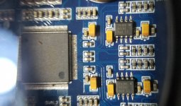
There are some 16 pin muting chips on the output. 1 for each XLR and 1 for rca. The left XLR chip (the one received 48v) has L+ and L- connected now so it is gone.
The audio still doesn't come from neither from R XLR nor from RCA.
So I am wondering how deep can be the damage and I would greatly appreciate some suggestions on how to find the failure.
3 Lme 49720 opamps in the buffer output
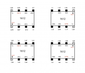
and 4 1612 in IV satge
There are some 16 pin muting chips on the output. 1 for each XLR and 1 for rca. The left XLR chip (the one received 48v) has L+ and L- connected now so it is gone.
The audio still doesn't come from neither from R XLR nor from RCA.
So I am wondering how deep can be the damage and I would greatly appreciate some suggestions on how to find the failure.
3 Lme 49720 opamps in the buffer output
and 4 1612 in IV satge
Attachments
Unfortunately noDo you have an oscilloscope?
Okay. If you can play an audio signal that a DVM can measure, say, maybe something like a 75 Hz tone (perhaps better if not 60Hz or 50Hz, depending power line frequency), then you can measure how far that signal is progressing through the output stage circuitry. Some free programs can generate such a signal. If you turn the test signal on and off, by using the DVM you should be able to get some idea of where in the circuitry the test signal is getting lost.
May I ask which version of D90 you have, the original with AK4499, or the newer version with an ESS chip?
May I ask which version of D90 you have, the original with AK4499, or the newer version with an ESS chip?
Thank you! I'll do it. Do you think I can find some schematics like this one? Evaluation board...
Logic tells me if there is no signal that comes from no one channel it can be powering or the dac chip as all the channels are on separate lines...Am I wrong?
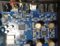
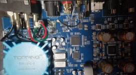
I have the original AK4499EQ version. I took some pictures (may be some one may need them)
Logic tells me if there is no signal that comes from no one channel it can be powering or the dac chip as all the channels are on separate lines...Am I wrong?
I have the original AK4499EQ version. I took some pictures (may be some one may need them)
Attachments
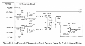
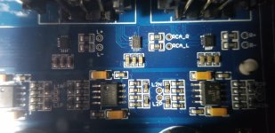
The output stage used in D90 is a little different from the AK4499 datasheet version.
The first part, the I/V opamps are same as the datasheet circuit. They are OPA1612 arranged around the AK4499 dac chip. The opamps are powered by +-11v rails.
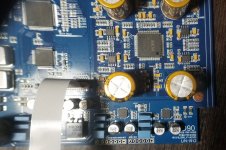
After the I/V opamps, there is some passive filtering of the analog audio like that shown in the AK4499 eval board schematic.
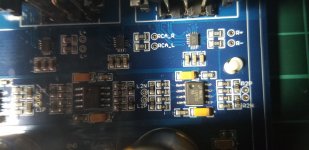
The passively filtered I/V outputs are routed to the opamps near the analog output connectors and mute circuits. The opamps in that location do differential summing, but without the MFB filtering that AK4499 datasheet shows.
XLR outputs are produced by differential summing of I/V opamp outputs. RCA outputs are then produced by differential summing of XLR outputs. IIRC the opamps near the analog output connectors are LME49720.
If you apply a digital test signal to the dac, a DVM should show AC voltage at I/V opamp outputs. Signals should be measured from the output pins to ground.
If an audio signal is present at I/V outputs then it should next be present at differential summing opamp outputs. If audio signals make it that far then could be only the mute circuits got damaged. Also, since the mute circuits are controlled by the MCU, there could be some risk the MCU got damaged.
The first part, the I/V opamps are same as the datasheet circuit. They are OPA1612 arranged around the AK4499 dac chip. The opamps are powered by +-11v rails.
After the I/V opamps, there is some passive filtering of the analog audio like that shown in the AK4499 eval board schematic.
The passively filtered I/V outputs are routed to the opamps near the analog output connectors and mute circuits. The opamps in that location do differential summing, but without the MFB filtering that AK4499 datasheet shows.
XLR outputs are produced by differential summing of I/V opamp outputs. RCA outputs are then produced by differential summing of XLR outputs. IIRC the opamps near the analog output connectors are LME49720.
If you apply a digital test signal to the dac, a DVM should show AC voltage at I/V opamp outputs. Signals should be measured from the output pins to ground.
If an audio signal is present at I/V outputs then it should next be present at differential summing opamp outputs. If audio signals make it that far then could be only the mute circuits got damaged. Also, since the mute circuits are controlled by the MCU, there could be some risk the MCU got damaged.
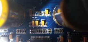
Sorry for late reply, I had to overcome covid. I did the measurements (1000 Khz signal), i put the results on the draw. I am a little confused how to interpret it. I also checked power lines. Voltage at control points on the board all correspond to their values. The only thing is that positive side has 2.9V and not 11V. Negative side -11V. The transformer gets hot (around 70C), time to take measurements.
Does MCU stand for the STM controller chip?
Does MCU stand for the STM controller chip?
Attachments
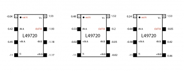
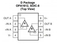
Please see the diagram below. Both OPA1612 and LME49720 use a standard dual opamp pinout.
Note: some readings may depend on the type of DVM used. Some measure RMS volts, some measure average volts and display as if it were RMS for sine waves.
Readings should be taken on both AC and DC meter settings.
For OPA1612 in D90, the V+ pin should measure +11vdc, near to 0vac.
V- pin should be -11vdc, near 0vac
Each of the two opamps in a dual opamp package has an output pin and two inputs. Pins 1 and 7 are the outputs. As can be seen from the diagram each opamp has a noninverting (+) inputs, and an inverting (-) input.
For the OPA1612 chips near the dac chip, the + inputs should be at about +2.5vdc, and 0vac. The - opamp inputs should measure near 0vdc and 0vac.
Before music (or a test tone) is playing the OPA1612 outputs should measure +2.5vdc, and 0vac.
With a test tone or music playing the OPA1612 outputs should measure around a volt or a few volts ac, and still at +2.5vdc.
The LME4972 opamps should measure about the same at the power pins as the OPA1612.
The DC offsets at the some (but not all) of the LME49720 inputs should be absent since part of the job of those oamps is to remove such offsets.
Similarly, DC offsets should not be present at the outputs of the LME49720. The most important thing to look for there is AC volts at the outputs (at least for now).
Best to start with the OPA1612 opamps, since opamp signal flow starts there.
EDIT: MCU is a sort of general term that stands for 'Microcontroller Unit.' The STM device should serve as one of those.
Attachments
The facts that your positive supply for the op-amps is around 1.6 V, and the transformer is getting hot, indicates that there is almost a short circuit of the +11 V supply to ground.
Most likely caused bu the mute IC, which was connected to the 48 V (phantom supply?).
The regulator for the +11 V supply is probably OK, but dissipating a lot of power due to the (near) short circuit. Luckily it has a thermal shutdown function.
Does anyone here know what the mute IC marked "3710" is?
I can see that you asked the question on audiosciencereview, but got no answers. It certainly isn't the Microchip device you posted a link to.
Mute switches might be similar or equivalent to something like: https://www.ti.com/lit/ds/symlink/t...yes&ref_url=https://www.mouser.com/&distId=26 ...Reason I say that is it seems like an unusual package for a quad analog switch.
Some others: https://www.mouser.com/c/semiconduc... of channels=4 Channel&package / case=UQFN-16
Some others: https://www.mouser.com/c/semiconduc... of channels=4 Channel&package / case=UQFN-16
Those TI Parts have way too low supply voltage. And perhaps the switches are not quad switches.
It looks like it is getting the +11V supply (at least that seems to be the case in the D90SE). Perhaps it generates the negative supply internally? The three capacitors connected to it could indicate a charge pump function as well as normal decoupling.
It looks like it is getting the +11V supply (at least that seems to be the case in the D90SE). Perhaps it generates the negative supply internally? The three capacitors connected to it could indicate a charge pump function as well as normal decoupling.
Okay. Looks like there are 3 mute switches on the board. If they are DPDT that might make sense. Each non-ground XLR pin connector (pins 2,3) could connect to one pole of a switch. In that case one switch would be needed for each XLR connector, and one DPDT switch for the 2 RCA connector channels.
The "3710" seems to be an SGM3710 from SG Micro. Not much information available on the internet though. A selection guide does show some information:
The maximum supply voltage is 12 V (single supply, the negative voltage is generated by an on-chip charge pump), which fits with the +11V supply available on the D90. It is a dual switch with the following features: "1Ω/11Ω, High Voltage, Rail-to-Rail Negative Signal Passing".
The package, and possibly the sourcing, doesn't exactly make it DIY-friendly!

A friend of me had purchase a Topping D90 equipped with AKM's DAC-IC AK4499 in used condition (via Amazon).
After checking with his present cd player in the PCM mode (44,1 KHz) he note only a hum on both channels at the cinch/RCA analog outputs and a distorted signal with a strong hum on both XLR analog outputs.
A second device of the same DAC model works fine without any trouble. This means, one can rule out that the reason of the not correct operation is to be found outside the DAC-device.
Bevor I start the troubleshooting procedure without any info concerning the circuit I will try to get a service manual or at least the schematic resp. circuit diagram.
Maybe one of the member can upload this or know an URL for download.
Thank you very much.
P.S.: here to find images from a similar device
https://www.audiosciencereview.com/forum/index.php?threads/topping-d90-mqa-teardown.20457/
- Home
- Source & Line
- Digital Source
- Topping D90 help