NE5532 decoupling capacitors
- By bengtssk
- Analog Line Level
- 102 Replies
Lately I've done a lot of reading about how to decouple the power supply rails of opamps. But I'm still not sure, so now I want to know once for all, what is the right way to decouple the op-amps?
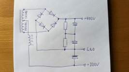
Let's assume I'm building a preamplifier circuit using a few NE5532 opamps (or similari). From that I learned so far the usual way to do this is to put two electrolytic capacitors at the the board, preferably close to there the PSU is connected to the board (to minimize that ripple current enters the signal ground). And then maybe also two smaller ceramic caps close to them as this;

Then, decouple each opamp power supply pins. This is what I'm unsure of how to do, but I be think there are three main options to choose from here. The first and simplest is to put a ceramic cap of 100nF between the two supply pins at each opamp. Like this;

The second option B is as suggested as almost all datasheet, one ceramic 100nF cap or so as close to each supply pins as possible, then to ground. The downside this this as that I be leave the signal and power supply ground should be separate at the board or very great care has to be taken with the layout, star grounding etc... So that ripple currents from the decoupling capacitor can flow through the signal ground.

The third C option I've seen is to put a capacitor as close to each supply pins as possible and the other rail, like this. This makes the distance from each power supply pin to decoupling capacitor shorter than in option A.

Option A and C has the advantages that no extra power ground is needed, simplification the board layout a lot. Question is if that is enough decoupling? Of course let's assume NE5532 (or similar BJT) op-amps and audio frequency use. And is C any improvement compared to A at all? Maybe overkill but ceramic caps are quite anyway.
Let's assume I'm building a preamplifier circuit using a few NE5532 opamps (or similari). From that I learned so far the usual way to do this is to put two electrolytic capacitors at the the board, preferably close to there the PSU is connected to the board (to minimize that ripple current enters the signal ground). And then maybe also two smaller ceramic caps close to them as this;
Then, decouple each opamp power supply pins. This is what I'm unsure of how to do, but I be think there are three main options to choose from here. The first and simplest is to put a ceramic cap of 100nF between the two supply pins at each opamp. Like this;
The second option B is as suggested as almost all datasheet, one ceramic 100nF cap or so as close to each supply pins as possible, then to ground. The downside this this as that I be leave the signal and power supply ground should be separate at the board or very great care has to be taken with the layout, star grounding etc... So that ripple currents from the decoupling capacitor can flow through the signal ground.
The third C option I've seen is to put a capacitor as close to each supply pins as possible and the other rail, like this. This makes the distance from each power supply pin to decoupling capacitor shorter than in option A.
Option A and C has the advantages that no extra power ground is needed, simplification the board layout a lot. Question is if that is enough decoupling? Of course let's assume NE5532 (or similar BJT) op-amps and audio frequency use. And is C any improvement compared to A at all? Maybe overkill but ceramic caps are quite anyway.