https://www.ti.com/lit/an/slaa788a/...=https%3A%2F%2Fwww.ti.com%2Fproduct%2FTPA3245
This document describes how to create a negative feedback loop for the TPA3255. Makes sense for the most part, but I think I'm a little lost on some of the finer points.
1) There's a table that prescribes a list of components in order to make the loop. It does not however give too much on why specifically those components and values are chosen. It says "for stability", but why in those amounts?
2) The design, like the reference, calls for an initial filter of about 50khz. In the spec sheet, it says the chip is capable of 100khz bandwidth. Is there as specific reason, or is that just the number they chose?
3) At the output, it has a zobel which is, again, said to be there for stability's sake. The thing that confuses me is the zobel isn't used in any amounts that correlate with a load. I thought you needed a speaker in order to complete the function?
Right. But why is there one in the circuit that isn't referencing the load? Is it for the inductor at the front of the filter?The Zobel just counteracts the inductance in the speaker giving the amp a more consistent load.
I cant see any extra zobels.
There are 1 on each output so four in total.
The L and C on the output are just the HF filter.
There are 1 on each output so four in total.
The L and C on the output are just the HF filter.
Yes, but doesn't the speaker need to be taken into account in order to do the math?There are 1 on each output so four in total.
Also interesting is the fact that in that TI PFFB spec sheet the recommended Zobel network is 220 nF + 1Ω, while the traditional Zobel it usually is 100 nF + 10Ω.
Unfortunately, the engineers who designed the TPA32xx have long since left TI and there appears to be no one left at TI who can answer questions about design options.
Unfortunately, the engineers who designed the TPA32xx have long since left TI and there appears to be no one left at TI who can answer questions about design options.
Oddly specific, right?Also interesting is the fact that in that TI PFFB spec sheet the recommended Zobel network is 220 nF + 1Ω, while the traditional Zobel it usually is 100 nF + 10Ω.
That's a shame. To greener pastures I hope. It's still one of the best chip amps on the market. Would be a hell of a thing to put on a resume lolUnfortunately, the engineers who designed the TPA32xx have long since left TI and there appears to be no one left at TI who can answer questions about design options.
Wow I had no idea it was that old! I guess that also explains the marketing of some of their newer audio products. Seems TI can't shake off its own shadow 🤔 Even a lot of old burr brown products are still some of the best TI has, and in some cases, are industry best.Yes this still is a very good chip amp, born at TI Audio R&D... 10 years ago!
There is a huge thread on TPA3255 in Class D that talks about a lot of these things. But if your specific question is why TI picked the various values for their PFFB implementation, it is a design choice with tradeoffs. There are several folks on that thread who are quite expert at the TPA3255 feedback setup who might be able to answer:
https://www.diyaudio.com/community/threads/tpa3255-all-about-diy-discussion-design-etc.287470/
I used PFFB on TPA3255 but I left the Zobel as it was on the non-PFFB and did not have any issues with oscillation.
https://www.diyaudio.com/community/threads/tpa3255-all-about-diy-discussion-design-etc.287470/
I used PFFB on TPA3255 but I left the Zobel as it was on the non-PFFB and did not have any issues with oscillation.
At that same thread there were even more strange things like the so called "differentiating postfilter", i.e., a proposed a kind of very simple PFFB (it used just a single 100pF capacitor from loudspeaker out into audio in, see post #32) that, according to its author ("bucks bunny"), would acomplish some kind of almost flat response audio nirvana.
Well, in truth, that author said somewhere in one of its posts (post #64): "I am wearing hearing aids btw for several years"...
Well, in truth, that author said somewhere in one of its posts (post #64): "I am wearing hearing aids btw for several years"...
That filter by @bucks bunny is real. He’s a huge contributor and one of the experts I am referring to.
Well, about @bucks bunny and as seen at post #20 on other subject: "What I don't understand is the astronomically improbable coincidence that Voltwide's 2018 circuit (featured in this thread) is virtually identical to Bucks Bunny's July 2020 circuit. Every component value, every component label, even the names given to circuit nodes (like Base3 and Base4) is identical - except R4 has been increased from 1 ohm to 220 ohms, and V2 is set at 12 volts instead of stepping through four different values."
So, until now, we have someone who says "I am wearing hearing aids btw for several years" and that seems to have a past record of "borrowed ideas without due attribution", who talked about a great new idea of a so called "differentiating postfilter", better than TI own PFFB, humm...
So, until now, we have someone who says "I am wearing hearing aids btw for several years" and that seems to have a past record of "borrowed ideas without due attribution", who talked about a great new idea of a so called "differentiating postfilter", better than TI own PFFB, humm...
I think you are too fixated on identities. Seems voltwide changed name to 29285 which was then disabled. I know that I used many of his suggestions, whether he is now someone else or perhaps same as bucks bunny, I don’t know. Just take their suggestions and designs on face value without worrying about them attributing it.

Welcome back Voltwide/29285!
Someone had a question about your 20pF PFFB scheme. Do you have a link to a schematic somewhere?
Someone had a question about your 20pF PFFB scheme. Do you have a link to a schematic somewhere?
I do not find the old thread, but here are some essential files concerning TP3118. These things apply also for TPA325x and many others, I assume.
Attachments
-
FQR_TPA3118BTL_PFFB_2021_03_21.asc4 KB · Views: 127
-
TPA3118BTL_PFFB_2021_03_22.asc4 KB · Views: 111
-
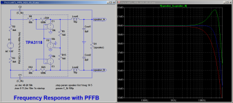 Simu_FQR_TPA3118_PFFB.png27.2 KB · Views: 221
 -
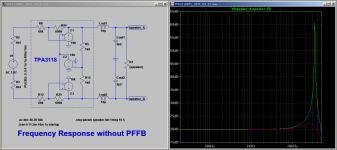 Simu_FQR_TPA3118.png24 KB · Views: 215
 -
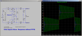 Simu_SQR_1kHz_TPA3118.png26.3 KB · Views: 207
 -
 Simu_SQR_1kHz_TPA3118PFFB.png25.6 KB · Views: 226
 -
3_tweaking_TPA3118_postfilter_feedback1.pdf31.7 KB · Views: 124
Those are some really encouraging and amazing results. So it looks like for TPA3118 or 3116, adding a 100pF feedback from speaker out to signal in is what is needed. For amps that are not balanced input (the negative input is tied to GND via a cap), is the feedback cap still the same value?
I have some TPA3116 amps I would like to try this on.
Where did you get an LTspice model of the TPA3118 amp from or is that an approximation?
I have some TPA3116 amps I would like to try this on.
Where did you get an LTspice model of the TPA3118 amp from or is that an approximation?
- Home
- Amplifiers
- Chip Amps
- TPA3255 Feedback Questions