Aiyima TPA3251 Modification Build Thread!

I'm starting this TPA3251 Modification Build thread so that everyone has a direct path for any and all modifications they wish to explore.

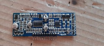
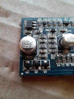
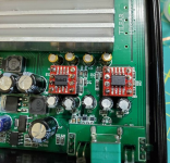
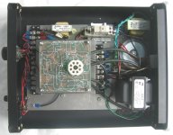
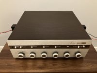
Like many of you Class D fans, I purchased the Aiyima TPA3251 A04 amplifier. After break-in and listening to it for awhile I realized that even though it sounds pretty darn good, it could potentially sound even better. So I then started to research what mods I thought it should get, after a lot of contemplation I came up with my build plan. Though my build plan exceeds the cost of my initial purchase price of ~$42 dollars, I believe I will end up with a Class D amp that sounds better than "many" higher dollar name brand amps. Plus this is simply a fun build, so I'm totally good with spending a few extra dollars in the quest to achieve magical sound.

For anyone that owns an Aiyima TPA3251 and is interested in modding it, please post up any & all mods that you've made or plan to make with pictures if possible. This way we can learn what works best with new innovative ideas. Also please state where you're buying your new parts from, this is very important because there are many fakes on the market. Almost* everything on my list was bought from either Mouser or Digi-Key USA, this way as a community we'll know that the sound performance we get is from a genuine part and not a fake.

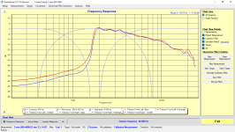
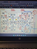
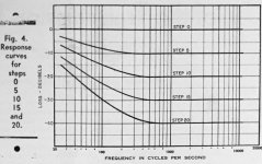
My personal volume listening range is marked in Red and my Klipsch 8Ω speakers are very efficient at 95dB, thus the reason I chose the 10 uH inductors. If you like to play your music louder/harder Or you have less efficient speakers which requires you to push the amp harder, then you might want to consider a 7 uH inductor with the appropriate capacitor uF rating.

[0%----I-----25%----------50%---------75%----------100%] Of the usable volume range.

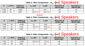
Texas Instruments LC Filter Design:
Page #17 (3.8 LC Filter Quick Selection Guide)
https://www.ti.com/lit/an/slaa701a/...A%2F%2Fwww.ti.com%2Ftool%2FLCFILTER-CALC-TOOL

8Ω Efficient Speakers Driven Light To Medium Hard = 10 uH Inductors & 0.47 uF Caps / 8 Ω Speakers Driven Medium Hard To Very Hard = 7 uH Inductors & 0.47** uF Caps

6Ω Efficient Speakers Driven Light To Medium Hard = 10 uH Inductors & 0.68 uF Caps / 6 Ω Speakers Driven Medium Hard To Very Hard = 7 uH Inductors & 0.47 uF Caps

4Ω Efficient Speakers Driven Light To Medium Hard = 10 uH Inductors & 1.0 uF Caps / 4 Ω Speakers Driven Medium Hard To Very Hard = 7 uH Inductors & 1.0 uF Caps

"From the results of the inductor study with the TPA3251 device, it is clear that the inductor plays a large role in the audio performance and total system power dissipation. Inductance value, DCR, linearity, and core loss factor into the total system performance and must be considered based on the design goals of a specific application. For the TPA32xx family of devices, a 7-µH inductor is a better value for performance-oriented applications due to improved linearity and generally improved distortion performance over higher inductances. However, for a more power-efficient system, 10-µH may be a better selection due to the reduced ripple current with a slight penalty on performance. In both cases, core loss must be considered as well as DCR. Although a 10-µH inductor may show improved power dissipation for low output power due to reduced ripple current, if it has high DCR, the losses may be greater at high currents than a 7-µH inductor with higher ripple current."

Humble Homemade HiFi Capacitor Test:

This is an excellent guide for choosing a capacitor.

Humble Homemade Hifi - Cap Test
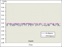
Bypass Capacitors:

"A bypass capacitor is a capacitor that shorts AC signals to ground, so that any AC noise that may be present on a DC signal is removed, producing a much cleaner and pure DC signal. A bypass capacitor essentially bypasses AC noise that may be on a DC signal, filtering out the AC, so that a clean, pure DC signal goes through without any AC ripple."

What is a Bypass Capacitor?

"Roughly speaking", the formula for choosing a bypass capacitor is 1% of the total of the capacitor you want to bypass. If you own an oscilloscope, that would be the best way to choose a bypass cap. Having said this, most use a 0.1 uF OR 0.01 uF bypass cap.

************************************************************************************************************************

My Modification Build List:

1) Op Amps, OPA1656 (2)
Elna RFS SILMIC II, 10 uF 25v Plus a Russian K42Y-2 PIO 10%, 0.1 250v as a "double" bypass cap combo on Op Amp pin 4 (Neg.) & pin 8 (Pos.)

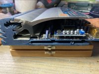
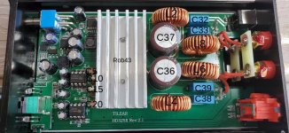
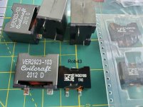
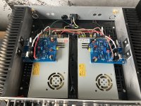
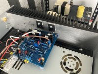
2) Wurth Elektronik 7443631000, 10 uH Shielded Inductors mounted on their sides to save space. (4), Location = L2, L4, L6, L8

2a) Coilcraft VER2923-103KL, 10 uH Shielded Inductors mounted on their sides to save space. (4), Location = L2, L4, L6, L8
At this point I will only recommend the Wurth Shielded Inductors, the Coilcraft are to big and mounting them will be difficult.(See post #4)

3) Nichicon LKG Gold Tune, 3300 uF 50v, LKG1H332MESZBK*** (2), Location = C36, C37 (High Ripple Current at 2.8A)
Wima MKP 10, 0.1 uF 250v OR Russian K40Y-9 PIO 10%, 0.1 200v (2), Location = C36, C37 as a possible Bypass Cap.

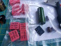
4) Russian K42Y-2 0.47 uF 160v PIO 10%. (4), Location = C32, C33, C38, C39
Wima MKP 10 OR Rifa PHE426 0.01 uF 250v (4) Location = C32, C33, C38, C39 as a possible Bypass Cap.

4a) Russian KZK K78-34 0.47 uF 250v 5%. (4), Location = C32, C33, C38, C39
Wima MKP 10, 0.01 uF 250v OR Russian K40Y-9 PIO 10%, 0.01 200v, (4) Location = C32, C33, C38, C39 as a possible Bypass Cap.

4b) Wima MKP 10, 0.47 uF 250v, MKP1F034704J00JSSD, (4), Location = C32, C33, C38, C39
Russian K40Y-9 PIO 10%, 0.01 200v, (4) Location = C32, C33, C38, C39 as a possible Bypass Cap.

4c) Kemet (Rifa) PHE426 0.47 uF 250v, PHE426HB6470JR06, (4) Location = C32, C33, C38, C39
Russian K40Y-9 PIO 10%, 0.01 200v, (4) Location = C32, C33, C38, C39 as a possible Bypass Cap.

5) Elna RFS SILMIC II, 22 uF 25v, (4), Location = C5, C10, C15, C20
Russian K40Y-9 PIO 10%, 0.01 200v (4), Location = C5, C10, C15, C20 as a possible Bypass Cap.

6) Meanwell LRS-200-36, 36 Volt / 5.9 Amp Switching Power Supply. (1)

7) Nichicon LKG Gold Super Through, 2200 uF 50v, LKG1H222MESACK (1), Smoothing Capacitor for the positive & negative output terminals of the Meanwell LRS-200-36 PSU. Bypass capacitor choices will be the Wima MKP 10, 0.1 uF 250v and the Russian K40Y-9 PIO 10%, 0.01 200v.

8) Volume Potentiometer, I'm totally open to suggestions because the stock Aiyima could be better. Size of course is a major concern.

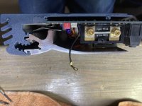
9) OFC 20 AWG (2x = 17 AWG) pure copper build wire and silver solder.

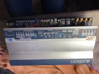
10) Everything gets plugged into my Panamax M4300-PM surge/power conditioner for cleaner power.


Rob43


* The K42Y-2, K78-34, & K40Y-9 capacitors come from Russia.

**This is a guess, I'd also consider trying a 0.39 uF capacitor. Possibly a Kemet (Rifa) PHE426 0.39 uF OR KZK K78-34 0.39 uF 250v in this location.

*** This capacitor is 50mm's tall and will require case modification to fit.

Attachments

  • thumbnail (2).jpg
    thumbnail (2).jpg
    167.9 KB · Views: 5,381
  • thumbnail_(20)_-_Edited_(2) - Edited.png
    thumbnail_(20)_-_Edited_(2) - Edited.png
    576 KB · Views: 5,468
  • thumbnail_(18)_-_Edited_(4).png
    thumbnail_(18)_-_Edited_(4).png
    717.5 KB · Views: 5,608
  • thumbnail (1).jpg
    thumbnail (1).jpg
    113.7 KB · Views: 5,447
  • basics1_-_Edited.png
    basics1_-_Edited.png
    24.3 KB · Views: 4,929
  • thumbnail_(27)_-_Edited.jpg
    thumbnail_(27)_-_Edited.jpg
    125.9 KB · Views: 2,400
  • Screenshot_2020-06-30_at_4.35.53_PM_-_Edited.png
    Screenshot_2020-06-30_at_4.35.53_PM_-_Edited.png
    108.3 KB · Views: 2,368
  • thumbnail_(23)_-_Edited_(1).jpg
    thumbnail_(23)_-_Edited_(1).jpg
    114.1 KB · Views: 2,332
  • thumbnail_(22)_-_Edited_(1).jpg
    thumbnail_(22)_-_Edited_(1).jpg
    106.7 KB · Views: 2,449

DCX2496 PC software under windows 10/11?

I'm upgrading my music server and finding that the most "recent" DCX2496 remote app (v1.16a) (a 32-bit app circa 2005) no longer functions correctly (for me) after upgrading to Windows 10 (or 11). I'm a Mac guy so I run Windows for the few things I need it for in a virtual machine (VM) under a product called Parallels. In the past I ran the Behringer app under XP and then 7 VMs and it worked fine. I now need to upgrade to Windows 11 (ARM) to run on a Mac Studio M1 and the Behringer app doesn't play nice. For sanity, I also tried it in a Windows 10 (x86) virtual machine on an Intel Mac which also misbehaves.

I'm trying to figure out if the problem is related to something else in my environment other than the just Windows version compatibility. Sooo... Does anyone have the remote app working reliably on either Windows 10 or 11?

The symptoms are that it starts up fine and lets me bring up the connect pane, select the unit and load it's configuration, dismiss the connect panel and play all I want -- until I try to bring back the connect panel to change units (I have four) and then it all goes off the rails. The new connect panel doesn't appear. The missing connect panel shows up as a thumbnail when I click on the app in the taskbar but it won't display on the screen. Even Task Manager can't kill it. I can launch another instance of the app but the zombie has the COM port locked. I've tried various suggested (and not) flavors of Windows compatibility modes but no dice. The app itself seems to "work" and the issue has to do with its interacting with the windowing system. I'm not enough of a Windows guy to proceed further under the hood.

I've searched quite a bit and no one else is mentioning this so either it's just me or no one is using the control software on a recent 'puter.

The wall around Behringer's tech support (aka the MusicTribe website) is all but impenetrable...so no help there.

Anybody tried the DuinoDCX project?

Any thoughts?

Thanks, Louis

Mercedes Sprinter NVC3(soundsystem /w headless unit)

Hello gals and lads, i am new to this forum and a newbie with electronics in general. I have been reading this forum from time to time but it's really too much information for someone like me to wrap my head around how things work, let alone all the countless questions i'm getting that for the majority of the members here seems common knowledge.

So let me explain what i'm trying to build and i hope for some feedback from you.

I want to build a headless car radio system with the only connections being bluetooth and aux.

Let me list what i have gathered till now.

Bluetooth board: ESS9038+QCC5125 Bluetooth 5.1 Decoder Board
https://www.ebay.co.uk/itm/165645010831

TPA3116D2 50Wx2 Version Finished Stereo Digital Power Amplifier Board
https://www.amazon.com/TPA3116D2-Official-Version-Finished-Amplifier/dp/B07TZYJQX4

Other boards i have that i may want to use but i haven't figured out yet how(meaning the right way of connecting everything):
FreeDSP Aurora
FreeDSP Classic(2 boards)

Also next to buy is:
Audio System M-165 EVO 2 - MB132(speakers and tweeters)
https://en.audio-system.de/products/speaker/m-series/

Rockford Fosgate Punch Single 12" 300 Watt Amplified Subwoofer P300-12
https://rockfordfosgate.com/products/details/p300-12/

Now, i bought the Bluetooth board cause that seemed to be the most expensive(hence the best?!) and the amplifier cause i have heard many praises about the TPA3116, but i haven't yet figured out if it will be best used for the mids or highs.

Now ideally i guess will be to get an AudioControl d-5.1300 or visit an audio shop and call it a day, but, i would like to build something myself. I like the DIY boards and the challenge of trying to make a sound system on my own.

Has anyone of you any suggestions?
Thanks in advance for your time.

Papst Motor Question - Changing Rotational Speed by Changing Frequency

I have a question about the Papst external rotor type motor operating in a Fairchild 412-1. I can get it to work very well at 60 Hz and 110VAC. But the problem arises when I try to increase the turntable speed to 45 rpm by increasing frequency.

I've been an avid follower of the threads about motor controllers. Several years ago I used the SG-4 generator to drive a Papst external rotor type motor. I did this relying heavily on suggestions in a couple of the SG4 threads (especially comments from @ralphfcooke ) and operate it as a 3 phase with no run capacitor. That project powered an Empire 208 and it has worked perfectly for several years.

I'm currently working on a Fairchild 412 that has the same motor. In this case I thought I'd just leave the run capacitor installed and create a simpler controller that just outputs line voltage and let the run capacitor create the 3rd phase. This setup works fine at 33 rpm, operating at 110VAC and about 60Hz. The problem arises when I try to increase the frequency for 45 rpm operation. The 412 is a single speed machine (i.e. no mechanical speed changer). If I increase the frequency to about 81.8 Hz, the motor slows noticeably and eventually stalls. I am wondering if this is caused by the amount of phase shift from the capacitor being impacted at a different line frequency (I believe phase shift is frequency dependent). I can get it to operate properly at 81.8Hz if I increase the voltage to about 139VAC. However I worry about operating the motor at substantially higher voltage than its rating.

I would great appreciate thoughts about this situation. Will this simple approach work or do I need to go to full 3 phase operation?

Thanks.

Richard Lee's Ultra low Noise MC Head Amp

For reference and future posterity, I've loaded Richard Lee's head amp schematic and his commentary about it up on hifisonix.com - its there if you need it.

Any questions, please post them here - maybe Richard can chime in.

Richard Lee’s Ultra-Low Noise MC Head Amp


And here is the updated (03 July 2019) MC Head Amp Compendium:-

MC Head Amp Circuit Compendium

Pass Labs F5 Burned Channel

A friend i know just bought a secondhand F5 clone. After listening for approximately 10 minutes at moderate volume the amplifier started smelling and we turned it off immediately. Upon closer inspection the 0.47ohm resistor are burnt and one has even desoldered itself.

Could anyone help with figuring out what might have caused this? And how to best approach a repair.

Thanks 🙂

Attachments

  • IMG_1823.jpeg
    IMG_1823.jpeg
    544.9 KB · Views: 187

Krell PAM-3

Mint Krell PAM3 preamp
Killer phono section MC and MM w/selectable loads
CD input has phase correcting filter via dip switches
Dual outboard power supplied
All new Nichicon 105deg caps in both power supply and regulators in preamp.
Manual included
This preamp is built like a tank
I’ll take the cover off and take pics for serious inquiries.
Near Mint
$1499 obo

Attachments

  • IMG_0279.jpeg
    IMG_0279.jpeg
    340.4 KB · Views: 110
  • IMG_0278.jpeg
    IMG_0278.jpeg
    349.5 KB · Views: 125
  • IMG_0165.jpeg
    IMG_0165.jpeg
    540.1 KB · Views: 111
  • IMG_0163.jpeg
    IMG_0163.jpeg
    425.9 KB · Views: 103
  • IMG_0164.jpeg
    IMG_0164.jpeg
    449.2 KB · Views: 108

Trio / Kenwood Solid State Stereo Amplifier TK-250T

Hi guys.
Someone dropped in a Trio / Kenwood Solid State Stereo Amplifier TK-250T, for repair.
Right away I noticed a damaged balance control, and after opening the amp, it was full of dust.....
I cannot find anything about this amp online, maybe someone knows this amp and can give any info.
A service manual would also be nice...

Attachments

  • IMG-20231220-WA0082.jpg
    IMG-20231220-WA0082.jpg
    40.1 KB · Views: 107
  • IMG-20231220-WA0083.jpg
    IMG-20231220-WA0083.jpg
    35.4 KB · Views: 90

Superbowl Blowout: Markaudio CHN110, Fostex FF125WK + FE166NV2, Fostex FE126NV2 Pair, Faital 6PR120, Lot SB Acoustic etc.

Selling the following:

Mark Audio CHN110 New $20: https://www.ebay.com/itm/276330924726

Fostex FE126NV2 Pair New $50: https://www.ebay.com/itm/276330941359

Fostex FF125WK + FE166NV2 New $80: https://www.ebay.com/itm/276330944474

Faital 6PR120 New $50: https://www.ebay.com/itm/276330934960

Lot of Beyma 10BR60v2, Visaton WS13 E Pair, SB Acoustic 12MNRX2 , Silver Flute W14RC25 New $60: https://www.ebay.com/itm/276330928090


Please see my other listings for similarly well priced premium new drivers.

Better tweeters

I want to upgrade my 3 way active speaker with a better tweeter. Have celestion ftr15 3070c in Onken 360l, fostex 299 compression drivers such as mid, and BMS4538 as tweeters. I'm missing a bit at the top like crunch and details. The BMS is comfortable, but a little too kind.

BMS4538 mediates i JMLC 1000. Active sharing is currently set to 800Hz og 4000Hz.

Attachments

  • AL_3.png
    AL_3.png
    31.3 KB · Views: 314
  • IMG_20230312_094648.jpg
    IMG_20230312_094648.jpg
    283.4 KB · Views: 313

Low B+ supply voltage to collector on one side of stereo.

I have a Marantz 2200 stereo receiver. The right output is fine. The left output is almost non existent, only if I max the volume do I hear anything and it is distorted and very very low in volume. I have did some trouble shooting and eliminated all the source inputs. Phono, FM, AM, Tape in out, and Aux. A 1khz test sine wave was used and both channels reach the Tone Amp Board (P500). Good output on the right channel, very very low distorted on the Left. Upon further volage test I found that the collector voltage on the Left channel transistor H506 is way down to 1.9 vdc. It is supposed to be 10 vdc. Supply voltage starts at 35 v. The opposite Right channel collector voltage is correct at 10 vdc. Any ideas where this large voltage drop is ocurring? I test R 518 out of circuit and its good but in circuit seems to be dropping way to much voltage. I will post schematics of the portion where the problem is and a whole schematic.

Attachments

  • 20240211_172114.jpg
    20240211_172114.jpg
    511.6 KB · Views: 72
  • 20240211_171655.jpg
    20240211_171655.jpg
    570.7 KB · Views: 85
  • 20240211_171954.jpg
    20240211_171954.jpg
    558 KB · Views: 74

McIntosh DA2 Digital Audio Module

Hi folks,

I own a McIntosh C53 Preamp, which is the one with the 'new' DA2 Digital Audio Module.

Recently, the USB port stopped working.
When I plug-in the USB cable to my computer, it is not recognized, essentially, nothing happens.

I did all possible tests:
  • Uninstalled/re-installed the McIntosh driver
  • Tried a different laptop (W10 on both) - issue persists
  • Tried another USB cable, no joy
  • Sound settings in W10 does not show up the McIntosh driver at all.
  • Tested both Coax and Toslink ports, all working good.
  • Factory reset on the C53
I think I can safely conclude that the USB port on the C53 went defective.

I see that McIntosh sells this module and it is readily available in authorized stores

However, everybody seems to recommend to take the amp to an authorized McIntosh technical service.
Now, I could possibly do that, but I would cost me twice the price of the module, because my closest repair center is 700 miles away.
Also, I would end up in leaving them the preamp for approx 4 weeks or more, especially should they have to order the module from McIntosh.

From what I can see, this module is kept in place by 4 screws on the PCB and 2 external ones, plus the connector to the main board.

052-057_Hifi_12_2020-005.jpg


In theory, replacing it should not take more than 30 mins. and it is not a difficult work to do.

It is like a plug & play, but I may be missing something, which is why I came on this forum to ask.

I really want an unbiased opinion.

Certainly, I am wondering why I have to pay more than $1000 to replace a USB port, given that all the rest is working fine.
If the USB only is not working it might be reparable, but at the end, it would cost me the same and many weeks of waiting time before I can get it fixed.

One of the authorized technical services told me they have seen more machines with this same issue, some can be repaired, some others need the module to be replaced..

This is why I am thinking to replace it myself, but I would like to read other experts opinion here, as it seems too easy for me to be true.

Thank you!
Alex

Open baffle U frame question

Hello All,

I love my open baffles but the full-range driver sits quite a bit above my ear position and would love to drop it down. The easiest way to do this would be to eliminate one of the woofers. The question is whether or not adding a 14" wing (gives me 6db gain) is the same as just adding the second driver? Does the driver see a difference in more excursion or distortion level or is it "free" db? If it's free then I can just add the wing and ditch a driver and place the full-range driver at ear height. Or should I make this an mtm? Some day I would love to make this a coaxial design with just a woofer at the bottom, and a woofer/compression driver coaxial situation up top.

Thoughts? Also my response in room above 300hz is pretty trash as far as smoothness in the response ( I can upload some sweeps if anyone is interested). I think would need to move the listening position which I can't really do in this room due to some load bearing pillars behind the couch. They are about 3 ft from the front wall.

Open-Baffle.jpeg

WTB Thiel 0F/8424G02 or DRVM-060-001 (Scanspeak 10F, with Teal Truncated Frames)

Long shot, but I wanted to see if anyone had a pair of the Thiel 10F/8424G02 or DRVM-060-001
(Part # depends on whether you're referencing Madisound's part number or Thiel's part number.)

They're the Scanspeak 10F's with the teal colored truncated frame. Let me know if you have a set collecting dust on a shelf somewhere. Thanks!

Subwoofer to make for mastering friend with Focal Solo Be

Sorry if this isn’t the right place but I have a very talented friend who masters for a living with these Focals and I’d like to build him a sub as a gift that he can use at will.

I’d like it to be nice certainly, but too nice and he won’t receive as the gift is intended as most of you know.

I’m mainly looking only to get to the high 20’s hz and the focals get to about 40. I’m pretty certain living close to Madisound I can source a good sub and plate amp (but suggestions always welcome) but would like help with any enclosures someone with experience might be able to suggest. Have the ability to build most enclosures. Thanks so much!

DUAL MONO TPA3221 Pictures Inside

Hi amigos,

Here a short review about the brand new TPA3221 :


Setup :

DAC : Gustard X16
Amp 1 : Hypex NC252MP
Amp 3 : Dual TPA3221 / OPA1652 (stock PSU 15V / 7a + FX Audio 24V / 4A PSU)
Amp 4 : HanZao TPA3255 / OPA1692 + Shui Yuan OPA1656
Playlist : HD audio via LDAC BT

Indroduction :
This dual TPA3221 is really small about 134x59x90mm, compared to the Aiyima A04 for example : 150X92x40mm.
The case is a full alu black enclosure, it's still pretty basic but rather robust. The connectors are pretty good and seem solid.

Under the Case, we therefore discover two distinct TPA3221 boards with a really surprising PCB. I would say the components seem to be of good quality
We see some Samsung FC power caps 35V@ 1800uf / Evox Film caps / Elna Audio caps / OPA1656.

The spec of the TPA3221 are available here otherwise:
TPA3221 data sheet, product information and support | TI.com


I did not measure the amp but in Living room (30m²) with my 2.5 floor speakers, the power is more than enough to drive my speakers under 8 ohms with a more than comfortable volume even with the stock PSU.

I made a 1h30 listening test VS my other amps and here are my observations with my favorite Playlist :

Bass :
Complex song : Downtown (Yellowjackets & WDR) : The bass is very well maintained, it is precise and it does not drool. Blindfolded, it is very difficult to perceive a difference in the human ear vs my Hypex NC252. Although I'm convinced the Hypex is better on paper. With the 24V PSU we gain slightly in power but it's also really good with the stock PSU. I hope that future reviews will confirm my opinion but the bass is tight and very present despite its small size)

Medium :
Audiophila Master CD18 : Voices stand out very well from the mix, they are well put forward. I found a very silky side in the mids, the amp is closer to the TPA3255 Hanzao / OPA1692 than to the Shui Huan OPA1656. I find my Hypex NC252 better in this register, however. Either way, I didn't find listening tiring.I let myself be carried away by the softness of the amp without any problem.

Trebles :
Being a drummer, I am particularly sensitive to this point. I used to collect cymbals and have a ticklish ear lol ) With the Drum Collections HD files : I found it to be very good, the rides are subtle, the crashes stand out without aggressiveness (I use a ribbon tweeter). Compared to my Hypex NC252, frankly it's quite impressive! We tickle his performance level. Overall very good behavior in the treble.

Soundstage :
Impressive! I have always found that dual mono configurations were more interesting on this point.
Audiophila Master CD 17 : Everything is well detached, the instruments are well distributed.
We find the signature of the TPA chips, it's as good as my TPA3255. I have always liked the TPA325X regarding the Soundstage and I am not disappointed here.


Negative points :
- The volume is reversed, we increase by going to the left) (can be corrected easily anyway)
- I would have preferred a Power Switch on the front for accessibility reasons
- With the 24V PSU, a tiny Pop sound when Switching ON only. Nothing to complain with the 15V.
- A strange behavior that I also observed: the start sequence is important here: I have to turn on my DAC before the amp otherwise I have a marked pop.
- No DIP8 op amps socket but OPA1652 seem really good !

Conclusion :
I paid the amp 56 euros ! It is a little bomb for this price : it is a small / compact and sounds very good. He does not blush in front of my Hypex and he will convince most ears. It lacks a bit of power it's true! But for a listening at moderate volume it is enough believe me! It is not at the level of my Purifi that is about 20X more expensive)))
At this price you will not take any risks! I think this little dual Mono TPA3221 is a great choice for less fortunate wallets.


VIDEO :

VID_20210329_205042
VID_20210329_205219


  • Like
Reactions: wchang

An Umbilical Question

Folks:

I'd appreciate some advice regarding hum and umbilical cables. My two-chassis Aikido preamplifier, which was built perhaps 15 years ago, has a small amount of hum. I've worked to reduce the noise and have had some success, but it isn't entirely gone. I suspect that the hum that remains is created in the 2.5' umbilical cable, where both AC and DC lines coexist. Is it likely that by rebuilding the umbilical cable and separating the AC and DC lines, each own its own braided copper sleeve, the hum would be eliminated or further reduced? I have lots of braided copper sleeve and could take this a step further -- the two B+ lines in one sleeve, heater in another, etc. -- if that might be a further improvement. All of the copper braids would be tied together and grounded, of course.

So, would twisted AC wires encased in braided copper sleeve running immediately next to DC wires encased in braided copper sleeve likely prevent the creation of hum in an umbilical cable, or will multiple braided copper sleeves bundled together have no effect on the hum?

Thanks in advance for your counsel!

Regards,
Scott

Attachments

  • Aikido Preamp & PS (top view) 040807.jpg
    Aikido Preamp & PS (top view) 040807.jpg
    58.8 KB · Views: 193
  • Aikido Preamp PS & Umbilical Cable 040807.jpg
    Aikido Preamp PS & Umbilical Cable 040807.jpg
    97.5 KB · Views: 200
  • Aikido interior (full with tubes).JPG
    Aikido interior (full with tubes).JPG
    424.5 KB · Views: 199
  • Aikido PS (exposed top view) 040807.jpg
    Aikido PS (exposed top view) 040807.jpg
    135.6 KB · Views: 193
  • Aikido Umbilical Cable 040807.jpg
    Aikido Umbilical Cable 040807.jpg
    52.9 KB · Views: 192
  • Like
Reactions: anthony.taylor1967

Looking for help with selecting a IRL2910 substitute.

Hi All,
I blew one of my IRL2910 (TO-220AB) output devices (Q115-Q118) in my R channel main amp and unfortunately these are no longer available.
Can I get help with deciding which of these substitutes to select?

IRL540N and possibly STP40N10L were recommended substitutes in another post from 10 years ago. Perhaps betters substitutes are available? And more recently IRLB4030PBF works according to this post.

It seems IRL540N would be the best option, but Rds On is higher. Will this cause more heat? Is there any reason to select another one? Another possibility is IPP12CN10LG.

I am confident Vgs Threshold given in the data sheet should fall between 1-3 volts. On my working L amp ( running IRL2910s) I managed to observe the following: The output devices seem to be paired and Vgs is the same for each pair. Across all 4 devices I’ve measured a range of 0.6 Volts to 2 Volts. Vgs increases on one pair while turning VR2 CW. Apparently the range in VR2 satisfies the Vgs Threshold for all devices.


Schematics attached( page 10 of 24 shows the Main amp section). VPWRR is around +/-58 Volts. Links to data sheets below. Thank you.

IRL540N
STP40N10L
IRLB4030PBF
IPP12CN10LGXKSA1

Attachments

Group buy SB acoustics baffles with waveguide

Hi. I really want to build up a small bookshelf speaker with Sb acoustics Satori drivers.

My plan is to produce the baffles with the waveguide machined into the baffle made of solid Richlite, and for either the 6.5” satori or 7.5” mid/woofer as one piece.

A single sheet would yield a lot of baffles and the unit cost wouldn’t be huge. And probably less than the aluminium waveguides that are currently sold with the high end SB tweeters. But the initial outlay for the 18-20mm sheet and double machining is fairly high.

So seeing if anyone wants to share the cost in a group buy.

If anyone is keen let me know.

What's Going On Here?

I'm trying to increase the B+ up to closer to 405VDCin this PS. As I reduce the choke size I go from
Figure A to Figure B. I understand there would be an increase in ripple with the smaller choke but the irregularity and "noise" increase seems out of proportion to the change. Things look really ugly if I lengthen the window. Figure C.
I seem to be able to get either much lower or much higher but can't find the sweet spot.
basic help would be appreciated.
Thanks

Figure A
4+7=395.jpg


Figure B
2.5+7=437.jpg


Figure C
2.5H+6H.jpg

musicman 2100-65 sixty five

Hello,

A friend dropped off an amp head for me. This is the model with an ECC83 in phase shifter. The amp dates from 1973-74.
The fuse blows. The power supply capacitors are original. An EL34 is rinsed. The transformers are not cut, The zeners are heated well.

After research, in addition to changing the 100uF 450V and 20uF 450v capacitors, I was thinking of changing the diodes and resistors of the power supply (low voltage and high).

zener by 5W, diodes on the el34 anodes by THT (4000v) + capacitors (MLCC, Through-hole, 1.5nF, 2kV dc, ±10%, dielectric: X7R)

I am giving you 2 diagrams because the one that interests us is illegible while the other is close (2475-130) and... more readable!

If you know these amps and/or if I make a mistake (with the 5W zener instead of 1W for example), please tell me.

Attachments

  • 2475 130 preamp.png
    2475 130 preamp.png
    239.6 KB · Views: 88
  • 2475-130 power amp.png
    2475-130 power amp.png
    186 KB · Views: 77
  • 2100 65.png
    2100 65.png
    315.7 KB · Views: 83

Anyone used waveguided ribbons?

I was reading someone's comments who had just bought some speakers with a ribbon tweeter and loved them. I had a college roommate, I helped him design some speakers with ribbons which he still has. Narrow directivity is often an Achilles' Heel of these (or if badly designed an Achilles' Hell as spell-check wants to write 😆). So I started thinking, how about waveguided ribbons? I recall a Dutch PA company using such, and I see Radian has a few waveguides for pro ribbons.

I'm really curious about this not-too-expensive item from Parts Express
https://www.parts-express.com/Dayton-Audio-PHT1-6-Planar-Horn-Tweeter-6-Ohm-275-087?quantity=1
has anyone used this? Or this Fountek
https://www.madisoundspeakerstore.com/ribbon-tweeters/fountek-neocd3.5h-horn-tweeter/

JLCPCB just changed the cost of via sizes

I have normally praised JLCPCB highly, for being super professional, cost efficient and the best out there for DIY prototypes.

How frustrating it is to now place an order and the get a mail saying I need to pay an additional 43 USD (ca. double up).

They have now placed an "option" in the ordering for via size (I did not see this), where you are charged extra for sizes smaller than 0.3 mm hole and 0.45 mm via diameter, this in order to do a 4-Wire Kelvin Test.

It's not so much that it costs extra to handle a PCB which is more difficult to produce, what is frustrating is that all my designs lately have been made with JLCPCBs recommended minimum via size of 0.2/0.4 mm, which has been produced without problem and without extra cost until now.

Now I will have to change all designs to avoid the very large extra cost.

If you change from 0.2/0.4 to 0.3/0.45, you will have hundreds of warnings and errors in your DRC check which will have to be solved one by one .... damn!

You might get away by using a 0.3/0.4 via, but it is not the best design I think to have only 0.1 mm larger ring then hole. .....

Multiple Entry.. Baffle?

I've never built or heard a Multiple Entry Horn, I probably will try it later this year as the idea is starting to appeal to me. But I'm already interested in how they typically use mid/bass cone drivers firing through smallish bandpass ports.

Particularly that it permits small (1/4-wavelength) centre-to-centre spacing yet with reasonably large and dynamic drivers, also offers reduced cut-outs for the nearby High-Frequency driver to diffract off, and (if I understand correctly) maybe some distortion benefits in constraining the cones. As always, there are down-sides, such as reduced bandwidth for the cone drivers.

Other concerns might include their output travelling down the horn and being reflected out again, HOMs, and the more complex, tricky design/testing/tweaking involved. But.. if you didn't need horn loading or the directivity control of a waveguide (e.g such as in a near-field scenareo), might using the same configuration but in a flat baffle work well? A baffle is in some ways a 180-degree waveguide, so I wonder if there is mileage in doing this. But I'm concerned that some of the MEH magic might indeed come from the horn.

All new territory for me, so before I get too involved I wondered what more experienced members though of the idea?
Thanks,
Kev
  • Like
Reactions: ErnieM

Raspberry Pi based source for in-car use

Hello everyone.

I'm currently working on an upgrade to my car audio system's source and I'd like to experimenti with a Raspberry Pi based solution for music playback and streaming.

My plan is to try out the various OS available for bit-perfect playback (Moode, Volumio and PCP) at home to see which one I prefer. The RPi will be operated 100% of the time via a mobile device connected to the car's WiFi network, so the ease-of-use of the various OS will be of primary importance, together with stability and resiliance. I don't need a DAC, (conversion managed by my DSP) just a reliable and high quality USB/digital player and transport.

Funtional requirements are pretty simple:
  • bit perfect playback of tracks stored on a USB stick and/or SSD HDD connected to the RPi with output via USB (then connected to an XMOS-based converter like the Hecate ARmature or SMSL PO100 Pro) or Coaxial SPDIF using a high quality transport HAT for the RPi (TBD based on performance and cost of the 2 alternatives)
  • ability to manage an auxiliary input coming from a Chromecast Audio connected via optical for streaming duties (I already have an iFi iPurifier2 for jitter reduction installed in the car)

I've ordered a RPi 5 4GB board and am starting to look around for solutions to get the optical signal into the RPi (don't need to control the CCA from the Pi, just the signal); unfortunately I'm not finding much info regarding compatiblity between the digital input HATs and the various OS, so I'm writing here in the hopes that someone could maybe provide some feedback on a proven solution.

So far I've found a few possible alternatives from Hifiberry and Ian Canada, at different price points, but that's pretty much it. Did I miss anything out there on the market?

If anyone has any pointers to help me move forwards with this project it would be much appreciated. 🙂

TIA

Finding voltage that has been recorded as .wav file data

I have some data recorded using some microphones saved using Studio One software as a .wav file. When I read the file in MATLAB using audioread function, I get decimal values with a magnitude of less than 1 that represent the waveform. I want to know what is the voltage signal signal that was recorded that is being represented by these values. I looked up the documentation of Studio One software but I cannot find any description on how it scales the voltage while saving .wav file.

Driver for JBL 708-ish dimensioned 2-way

Driver (8/10 inch) for JBL 708-ish dimensioned 2-way

I am searching for a driver that can perform comparable to what is achieved with the JBL 708. The thing that is hard to get is described as: Low fs, relatively low Mms, low Vas (or a combination of T/S that makes a slightly higher Vas feasible). Or not in T/S: extension and mid-range capabilities in a small enclosure.

Speaking of which:According to 'sound on sound', the internal volume of the JBL 708P is 27 Liters, which does not account for the volume of the drivers and amplification tray: outer dimensions of the speakers of 441 x 250 x 312 mm, build from 12 mm plywood sheets. But the JBL owners manual does not give anything else than this. I was told in another forum that the driver JBL 728G is probably very close or identical to the model of the previous monitors 218F, apart from Impedance, while no specs are available for the 728G.

The specs of 218F are:
Code:
fs: 45
Qts: 0.38
Qms: 4.2
Qes: 0.42
Vas: 26*
EFF: 0.55
PE: 200
Xmax: 15.7
Re: 1.8
Le 0.15
Sd: 0.215
Bl: 6.1
Mms: 31    

*(must be liters, despite they say imperial cu ft, which does not make sense at all)
With moderate DSP-use of +3 dB gain at 42 Hz, Q of 1.67, an f3 of 42Hz is reached.

Now I know it is too much to ask to get that performance for a cheap price, but something in the region would be very cool. I am currently reducing the size of my 2-way project from 12-inch to either 10-inch or 8-inch (preferably the first) and an enclosure of 30 internal liters and I am still searching for alternatives that can do both: extend and play mids. So far, I have found the 8-inch Peerless HDS-P830869, but according to forum member Michael Chua, it does not behave as the T/S suggest: Link 1, Link 2. It needs a smaller enclosure and this is not so good. Then, there is a very basic 10-inch Beyma SM-110/N driver. That one simulates well, better than the Faital 10PR320 in the low end (I am using the 12PR320 atm), but no information on its performance can be found.

I have been scanning many manufacturers now, but maybe I have missed something. The final enclosure is thought to be about 60 x 30 x 25 cm (30 liters) and a waveguide will play on top of the woofer, crossed over at ~ 1.2 to 1.4k. Maybe you know about something!

Regards

about upgrade Yamaha CDX630e clone Sony CDP750

Hello,

I just get a cd player Yamaha same as sony cdp 750. I would replace electrolytics, output caps, put a emi filter, replace some resistor by 1% arround 1541 and opa, diodes may be too.

Questions about psu :
sony cdp-750 page-0011.jpg

I only see a winding in the secondary for numeric and analogic tension. The diodes evoke a voltage doubler. Isn'it ?
Why psu caps (pre-reg) C203 100uF/204 330uF (analog) and C105 4700uF/106 3300uF (numeric) aren't symetric ?

A new transformer and power supply for analog could be necessary. What do you think about ?

Please take a look.
I can upload other pages of the diagram.

Stepped attenuator conversion help (SE to BAL)

Attached below is a 70-year-old passive loudness circuit schematic for use with a 23/24 position stepped attenuator. The second attachment is a graph of the transfer characteristic for select steps of the attenuator. It is a single-ended design that I am attempting to convert to balanced for use with a 4-deck 24-step attenuator from Goldpoint. This attenuator will be sandwiched between two Neurochrome Universal Buffer modules operating in a balanced configuration. The final attachment is my proposed balanced revision of the first attachment, (showing just the first 5 positions).

I am asking for assistance in verifying that my proposed revision correctly maintains the transfer characteristic of the original circuit.

Thanks in advance.

Attachments

  • FA2BDC09-ACEA-4989-8A20-C894A0E6A60E.jpeg
    FA2BDC09-ACEA-4989-8A20-C894A0E6A60E.jpeg
    471.7 KB · Views: 234
  • 010BFA0F-C2E5-410C-B8B4-93C0A884C5D2.jpeg
    010BFA0F-C2E5-410C-B8B4-93C0A884C5D2.jpeg
    250.3 KB · Views: 224
  • 6BC9DE95-B654-4174-8C2E-038016F8934A.jpeg
    6BC9DE95-B654-4174-8C2E-038016F8934A.jpeg
    446.7 KB · Views: 221

Pioneer SA710 (blue line) - cleaning Alps ASX-114 input switch

I've recently restored a Pioneer SA 710 (~1980 blue line integrated amp). After replacing the main capacitors (originals were down by 30% in terms of capacitance), replacing electrolytics in the power supply and in the pre- and main amp section, I was quite impressed by the sound that came out of my Special 40s. The switches seemed noise free, apart from the input selector which was cutting in and out, especially on the Aux position. With no significant improvement after several attempts of flushing the switch from the outside with electronics cleaner and Deoxit red, I decided to disassemble the switch.

Overall, it is a relatively straightforward job. The specific switch (Alps ASX 114) is used on many other amps of that time so if you want to attempt this, here are a few learnings:

  • be careful when removing the blue plastic push pull connector that runs between the selector knob on the front panel and the actual switch in the rear of the amp. It is connected to the switch by 4 plastic snap-on clips (one on each corner). I managed to safely remove the plastic connector by rocking it to one side. Once one or two of the clips come undone it is easy to remove the plastic cable from the metal switch housing
  • fully desolder the pins. the fit on the Pioneer PCB is ultra-tight (even without solder) and any tiny amount of leftover solder will make the removal difficult and/or lead to damage on the pins. I managed to break off a tiny bit from one of the pins but it was still long enough to make proper contact when I soldered the switch back in
  • The switch is held together by 6 metal tabs which are quite close to the pins. I used a cheap China electronics cutter to lever them open. The cutting edge easily slides under the tab and the cutter can then be used to gently pry the tabs up without damaging the contact pins (not great for the cutter so don't attempt this with your Knipex)
  • Once the switch is open, remove the plastic cap which transfers the motion of the blue plastic cable to the moving parts of the switch
  • Take photos! Note the orientation of the 4 small gold/copper tabs in relation to the front of the switch
  • The switch contacts are silver plated and the silver will get a patina over time, especially on the outside positions of the switch (where Aux sits on the SA 710). Despite trying for 10 minutes, no amount of deoxit red fully removed the silver oxidation. I used a non-abrasive silver cleaning cloth and got very good results. Don't forget the inside areas of the switch (in total 4 surfaces to clean)
  • the four little contact tabs that ride on the sliver-plated switch body seem to be gold plated and had very limited oxidation. I used a pipe cleaner with Deoxit red to clean them on the inside, the little wire of the pipe cleaner will help spread the tabs for cleaning but is thin enough to not permanently bend the contacts open
  • Re-assemble the switch (with a little deoxit applied) and carefully close the tabs after making sure the internals move freely. I used a flat head screwdriver with anti slip grooves on the tip (see photo) to ensure I don't slip and massacre the pins when bending the tabs
The switch should be fine for many year to come. Mine measured max contact resistance of 0.01 ohm after reassembly

Attachments

  • ASX114 assembled.JPG
    ASX114 assembled.JPG
    518.6 KB · Views: 104
  • ASX114 clean.JPG
    ASX114 clean.JPG
    473.5 KB · Views: 94
  • ASX114 dirty 2.JPG
    ASX114 dirty 2.JPG
    362.6 KB · Views: 94
  • ASX114 dirty.JPG
    ASX114 dirty.JPG
    362.1 KB · Views: 98
  • ASX114 inside.JPG
    ASX114 inside.JPG
    359.1 KB · Views: 94
  • ASX114 installed.JPG
    ASX114 installed.JPG
    492 KB · Views: 104
  • ASX114 metal tabs.JPG
    ASX114 metal tabs.JPG
    521.4 KB · Views: 97
  • ASX114 ready for assembly.JPG
    ASX114 ready for assembly.JPG
    433 KB · Views: 102
  • ASX114 switch.JPG
    ASX114 switch.JPG
    529.7 KB · Views: 103
  • Like
Reactions: huggygood

Aragon 4004 MK1 My amp is cutting out at random times while listing at lower levels.

Dose any one have an idea what might cause this? the problem started on the right channel but now it sometimes it both channels. i had it checked out 2 years ago and was told it was all original and working as it was intended. i was also wondering if anyone knew who would have quality parts for it. I love this amp it sounds amazing with the 28k pre amp and my mac 2100 by amping my kef speakers.

Frontman 20G

Hello everyone.
This is my first post here, and I'm not so much of an audio guru, but I know a thing or two in electronics but alas not enough to solve my problem.
Recently bought a cheap but new Fender Frontman 20G, for which I do not have the schematics but I've already opened it and made some observations.
My problem is the following: the amp seems to work, but it generates huge amount of main (50Hz in my country) noise.
  • If I do not plug anything in, there is some hum but rather acceptable for the price of the amp
  • If I plug a guitar:
    • If I put the sound at zero on the guitar or on the amp then close to no hum
    • If I put normal volume on the guitar and the lowest amount of volume (1) on the amp then I'm having some massive humming. Very loud, not faint.
      • If I plug the cable without the guitar it's more or less the same, perhaps worse.
  • The only thing that mitigates this is that I touch any metal part with my hand, on the guitar, on the cable or on the amp itself then the humming is reduced to acceptable levels, though still hearable. This fix is actually annoying because when I'm holding the guitar normally I'm not touching metal parts but evey time I touch the strings there is a short pop noise.
Here's what I checked so far:
  • Trying another power outlet: it makes zero difference, even on the one closest to the electrical panel.
  • Checking the protective earth (PE) connection: there is no misconnection issue whatsoever on the amp+cable+guitar setup. I can measure a solid 0.4 Ohm from any metal part of the guitar to the PE of the power cable of the amp. Every metal part in the amp is connected to the PE, and one of the sound outputs (let's call it the negative one) is connected to the PE, which I assume is a design choice.
  • I checked the audio output on the oscilloscope. With just the cable plugged in, I can see the 50Hz sinewave 2V Pk-Pk, and some 300Hz superimposed with a much lower amplitude
  • The power supply appears to be a center tapped transformer + full bridge rectifier for a +/- 20V power supply. The output ripple seems acceptable, and I believe that if the supply was the guilty element the noise would be at 100Hz and not 50Hz.
I do not have any idea on how to fix this. I live on an appartment on the 14th floor of an old building and rewiring the whole appartment is not an option.
If you have any ides or tips to solve it, I'd be grateful.

Demo box that compares tube to solid state preamps realtime

A few years ago in AudioXpress there was an article that was about comparing the output of a tube preamplifier to that of a solid state preamplifier. The design was especially well done. My plan was to add the ability to use external devices for comparison as well. The problem is, I CANNOT FIND THAT SILLY ARTICLE TO SAVE MY LIFE! Could somebody here please help me? I certainly would appreciate it.

Thanks in advance ....

New Headphone Day

I’ve never had a set of ”hifi“ headphones. The nicest set I ever had was the $20 in ears I got for my phone because I also needed them to have a mic. I’m not an audiophile, I have never auditioned any headphones, I wouldn’t call myself a critical listener.

After completing @alexcp omicron headphone amp, I decided to get some nice headphones, Grado SR225x. They sound great, pretty comfortable (without glasses) and seem reasonably priced. My music is a lot of classic rock, acoustic guitar and some 80s alternative.
  • Like
Reactions: alexcp

Box dimensions search with room modes

Hi there!

I've been using this to brute-force speaker box dimensions. Wondering if somebody else does this as well. If you play with it, please let me know what you think or what bugs you see.

What it does:
  • Grid search for box dimensions in X, Y and Z.
  • Compute volume and check if it's between the allowed tolerance
  • Compute the modes inside of the box
  • Use least squares to rank, using the distance between modes up to a limit frequency. Trying to distribute the modes rather than doing a global optimization. I found it was better. Many ways to do this.
It usually ranks well measurements with prime numbers or relative primes.

You can try it here: https://zsum.net/box_search/

1707607977809.png


Regards.
  • Like
Reactions: krevilplays and GM

static hiss at 0 volume that diminishes as I increase volume - no input

So, I just recapped, new tubed and adjusted balance and bias. Also did 2 dexoit sessions on the pins and sockets of tubes and all wipers and switches. At the 0 volume there is this white noiseish coming through the speakers and as I turn up the volume and at max (with nothing playing) it actually goes mostly away but is very faint. When music is playing I cannot hear it, just when there is no signal. Inserting shirted RCA plugs has no affect neither does changing to any other inputs or selections on the Stereo, mono, L, R.

It is a beautiful amp, very pleased with how it has turned out so far and would love to determine if this is normal (doubt it) or there are some usual players I can look at.

More cleaning? Maybe check other components along signal path? Ground? Any suggestions, thank you!

Attachments

  • IMG_1197.jpeg
    IMG_1197.jpeg
    474.3 KB · Views: 87

CD Player Laser Diode Current Voltage and Power

Hallo

See data sheet. I have a few questions about Laser Power, current and voltage. Example calculation: If I Calculate Laser current x Laser Voltage = 50mA x 2V = 100mW Where is the Calculation Error? Laser diode has a maximum power P = 5mW. What Voltage and Current is present at the Laser Diode?

So Power loss is around 100mW? Why isn't Power loss listed in the Data sheet?

What does Monitor Current mean in the Data Sheet?

Gruss Chris

Attachments

Hiraga Class A Build Question

Hello audio geeks

I won this incomplete build in an auction. I was going to complete it however wanted to first confirm before firing it up:

  • This build uses high current 24V SMPS, is an SMPS suitable for this build?
  • If the above is the case, I could consider a DIY Audio Store SMPS filter kit to block any conversion noise?
  • Otherwise, a conventional PS is better?
  • Is existing heatsinking likely to be OK, or inadequate? This is class A after all......

Keen for your thoughts. I can use the case for another build if this is likely to be a no-go.

Thanks all!

Attachments

  • IMG_1073.jpg
    IMG_1073.jpg
    541.5 KB · Views: 174
  • IMG_1074.jpg
    IMG_1074.jpg
    466.7 KB · Views: 181
  • IMG_1075.jpg
    IMG_1075.jpg
    375.6 KB · Views: 170

The amplifier does not turn on, the mosFETs get extremely hot. There may also be missing pieces in the solution. Or they may have moved. We can't see.

Amplifier models overheat. When you give power it gives 12 volts. And. It works on red, the green light is not on. We couldn't figure it out. 23 people looked at it before us, the masters looked at it. But we are trying to deal with it somehow. We couldn't get the green light to work and I couldn't get it to work. Can you help us with this? Respects.
20240119_212557.jpg
20240113_194223.jpg
20240119_211546.jpg
20240119_234312.jpg

Tweeter and Cap, Theoretical Speculation

As I start to work out a crossover upgrade for my ER18RNX/27TDFC, I've been considering cap upgrades for the tweeter and this looks interesting.

The speaker is good, the 27TDFC is good (way better than its price point might suggest), so a good cap e.g. alumen Z cap looks appropriate.
But what about a Jantzen Amber Zcap? Results could be spectacular.

But the cost of that cap would buy a better tweeter such as SEAS Crescendo, which Troels likes a whole lot and would appear to be usefully better than the 27TDFC.

So it make me wonder, if spending one way or the other, which mix would be best;
27TFC and Amber Z cap
Crescendo and a more basic cap like Claritycap CMR

All very theoretical but perhaps an interesting poser?

Phase check

Hello everyone. Hope you are all well.

I have something like an integrated amp that I am working on, and I would like to be able to check that I have not accidentally inverted any channels due to haphazard or simply ignorant wiring. What would be the best way to make sure that everything stays + and - from pre-amp inputs to amp outputs?

I don't think a "battery test" at pre-amp inputs will work since I know for sure there are coupling capacitors at pre-amp inputs.

Also, it will be extremely inconvenient for me to procure an oscilloscope, sadly.

Academy Audio VCU Muses volume control plus mini dual supply

Never really got round to using this properly as I went to a balanced source, so in as new condition and working order. The Muses is simply the best volume control available, no question.

Included is a complete mini dual polarity 15V 78xx / 79xx regulated supply module designed for me by the mighty Prasi. The built module requires dual secondaries so I will include a second improved PCB that will accommodate both dual and centre tapped windings. A BOM will be provided should the buyer need to build the second supply.

Also included is a 230V AC, 15 + 15V 2VA Myrra transformer with AMB mounting PCB - a whole solution ready to go. If the buyer wanted fancy low noise regulation, then build the green PCB up with 18V regs and strap some 15V LDOVR regs on the output.

For USA this PCB transformer should work.

The VCU has ben replaced by the VCX, so possibly a collectors item 😉

I highly recommend the VCU has buffers on the input or output depending on your source and end circuit impedance etc. Sjostrom Diamond buffers are superb but XRKAudio has developed some very good ones available in his Etsy shop:
https://www.etsy.com/uk/listing/1619024473/diamond-buffer-by-jhofland?ref=cart

SOLD

IMG_0553.JPG
SOLD

Pink Triangle Anniversary PSU

Hello everyone,

I'm working on a Pink Triangle Anniversary PSU, I can't find schematics or any info on the design on this so its a bit difficult for me to fully understand its workings.

The PSU switches on but it drives the motor into runaway speed. The issue started after the 12V batteries have been replaced with new ones. This is for both 33 and 45 rpm.

My understanding of how the PSU should work is:

Mains supply power to the electronics inside the PSU, the motor is driven from the big 12V (6+6) batteries and the speed control is achieved by the AC tacho attached to the DC motor.
I did check the motor separetly and suppling different DC voltages results in variation in the AC feedback so I belive the motor itself is operating correctly.

I'm able to track the AC feedback signal through the initial quad op-amp, it gets amplified and then it goes through a pair(NPN, PNP) of medium power transistors BD135 and BD136 and then it gets complicated for me as there is a comparator circuit (LM393N) two logic chips (MM74HC00N, MM74HC02N ) and a precision timer/oscillator chip (ZN1034E). All the chips have 5V supply present at Vcc pins. The basis of the NPN transistor seems to be came the signal output of the logic chip MM74HC00N.

I have changed the ZN1034 and the MM74HC00N. The transistor right of MM74HC00N is a BC639 NPN.

The C of printed circuit board goes to the left relay.
I have replaced the precision timer chip however the issue remains, all the trimpots seems to be working fine. PSU is fully recapped.
Is there anyone who can send a schematic of the anniversary psu?

Thank you very much for your help

Unorthodoxy - a Wharfedale W90D odyssey

If I can channel my inner Great Carnac, I’d say the answer to my question would be to unload the W90Ds and just build a proven DIY design. But I’ll don my fire-rated garments and ask anyway…forgive me if this offends anyone.

I’ve had these W90D speakers for several years and have made several attempts to bring them up to par. I’ve seen many comments about how easy and pleasant sounding the Wharfedales of this era are but these have never done much for me. I’ve tried the SX-780, my Denon AVR-3000 and currently a Kenwood Basic M1A in various settings and nary a positive twitch. My hand-me-down A25s (in comparison) sound just like many describe: perfect to listen to all day even without the highs and lows. And yes, the A26 or related alternate designs are on my radar.

I’ve got the original purple egg tweeters, but one had the broken Al lead so I pulled them and dropped in some Visatons. I also replaced all caps with the Dayton PMPC precision series and most recently grafted new L-pads. The crossovers still have the original autoformer and iron core inductor.

My build experience is limited: small bookshelf full rangers with Alpair 10P units. I like these.

Also, I’m working on the LX-Mini (no sub); bought the kit from Madisound and working out the assembly/construction.

But back to the W90D. These are the single cavity design with standard (not Alnico) woofers. It would seem from all the modern “Kate Moss” like designs (tall and skinny), the horizontal side by side layout is out of fashion.

Is there ANY potential to use the W90 cabs/enclosure with updated xo and drivers to make these worthwhile?

Full disclosure, I would exercise every option to be able to revert back to stock - for some reason I can’t adulterate a pair in decent shape. But I’m willing to exercise my CNC router to make the most of it.

I did try to offload these a while back but seems few had interest.

Ok, ready for the flames…..

Z

Are 'bad caps' still a thing?

I'm referring here to the capacitor plague era and premature failures, NOT sound quality.

The reason I ask is because yesterday I went over the 'lytic caps inside the PSU (SMPS) of an an approx. 10 year old Marantz UD7007 with an ESR-meter.
They all measured fine despite the fact that these were mostly no-name brands of Chinese make.
We're talking brands such as ZHN, KSD, Jicon, Lelon and TK (supposedly Japanese brand Toshin Kogyo). Of the latter, many of the fancier looking ones in the analogue board and some in the PSU were rebranded D & M (Denon & Marantz?). Only the Lelon brand was already familiar to me.

All measured fine, including the low-ESR types which would be the first to suffer problems.

Has the time come that we could say Chinese caps deserve a better reputation?

P1030532.JPG

Audison SRx 4

Hello,
I'm trying to remove the pcb from the housing of Audison SRx 4. The top cover (silver) holds the clamps of the transitors, but is very tight fitted to the blue part.. Is there a normal way to remove this..??? ..don't want to use brute force.

Attachments

  • SRx 41.jpg
    SRx 41.jpg
    84.4 KB · Views: 85
  • SRx 42.jpg
    SRx 42.jpg
    92.3 KB · Views: 90
  • SRx 43.jpg
    SRx 43.jpg
    112.8 KB · Views: 76
  • SRx 44.jpg
    SRx 44.jpg
    81.1 KB · Views: 86

Hifonics BXL2000D protection circuit issues

Long story short.
The amplifier powers up normally but the relay doesn't engage, the pin for it at the PS board is tied to q2, q3, q4. These have been swapped before me, all being npn which is odd, doesn't seem right. At least one should be pnp to pull to ground !? It's not the the relay itself, it works, tried it outside of the board. There is a 1n4148 diode between the relay and the PS board, changing this one did not do anything.

Does anyone know what they should be ? Q2, Q3 and Q4 ?

The other issue is the IRS 21844s is in shutdown mode (SD ~ 0.3v). Removing 2SD1302 on the main board, makes the amp play as it should. I've rebuild the DWM3640, was even able to source the MAX transistor...but i still get shutdown mode.

I've checked the voltage +-5v, +12v, +15 everything is fine...
PROT pin on the PS board is sitting at 1v, Not sure if this has to be 15v ?

Attachments

  • 1.jpg
    1.jpg
    923.4 KB · Views: 122
  • 2.jpg
    2.jpg
    482.3 KB · Views: 136
  • 3.jpg
    3.jpg
    614.4 KB · Views: 111

Hifonics Maxximus X4 protect

Working on a Hifonics Maxximus X4 2 channel class D, two boards in one housing. When switching on, it goes directly in protect, with very low inrush current.
When I quick "pulse" the remote of the power supply for about one minute , I got about +/-30V rail voltage. Inrush current about 1A. Power on and protect led is flashing.
Mosfets both boards PS and amplifier are OK.

I sustpect the protection itself, but I'm not familiar with the boards used.. some pics of the boards and PS driverboard. If there are schematics available for this amp or similar ones, that would be a great help for me.

hifonics_maxximus_x4_0.jpghifonics_maxximus_x4_0a.jpghifonics_maxximus_x4_1.jpghifonics_maxximus_x4_2.jpghifonics_maxximus_x4_3.jpghifonics_maxximus_x4_4.jpghifonics_maxximus_x4_5.jpg.

The elusive pin 13 (TEST) on the SAA7220?

Alright, which one of you brave lads has done the unthinkable and hooked pin 13, TEST, on a SAA7220 to VCC? Nowhere in the datasheet is there any mention of the function of this pin, other than it being pulled low internally? What happens when you hook it to VCC? Did anyone try? Or is this, a good 35 years to date, still unchartered territory? Should I venture there, and risk being pulled into a quantum time vortex and be transported back to Philips' Natlab in the mid 1980's?

pin13_saa7220.jpg

DIY full range OB

Hi all,

I'm considering to build a DIY OB using a full range driver together with one or two Peerless SLS 315 (12 inch) drivers per channel. I already own 4 Peerless SLS 12 drivers in total and I'm wondering if these would make a good OB canditate together with a 6 to 8 inch full range driver?

For instance a TangBand W8-2145, or a Lii audio Silver-8 driver. The latter has a rather low Qts by the way, not sure if that would suit a OB, although I've seen this driver in an OB configuration.

Experiences with Sica drivers?

Hi,

While looking for a 10" or 12" driver, I stumbled upon Sica drivers.

They can be had for very decent prices in a UK shop (hotrox) and look very well built with good specs.......but nobody seems to be using them which makes me suspicious right off the bat. no reviews, builds, ... It comes from the Jensen factory.

I was thinking about using 2 12" woofers, only 80GBP (about 100eur) each, in parallel so it' a 4Ohm load and active DSP with my minidsp 2x4HD. It's for a home application, crossed over at 800Hz to a CD.

https://en.toutlehautparleur.com/media/catalog/product/datasheet/sica/Z007831.pdf

It looks decently flat until 1.5 Khz in a ported enclosure of only 45L which would be very convenient, would cross them over at 800Hz to a CD with a 2nd or 3rd order.

Anybody any opinions on these? Would they best an equally cheap SB Audience 12MW200 or other middbass drivers?

Thanks!

Denon PRA-1500 input selector problem fixed

Just in case somebody else has the same problem: I fixed my Denon PRA-1500 input selector instability problem, and here is a short how-to:

Symptoms: after turning on the PRA-1500 the input selector switch (button operated) lost its memory, making it necessary to press the desired selection setting again and again. The problem went away after some time while the preamp was warming up.

Diagnosis: the preamp is built around a Toshiba TC9152P analog function switch. The TC9152P features an 'ALL_OFF' input with positive logic, which is connected in the schematic to a monostable operated by VDD. Any glitch on VDD higher than 0.8V will trigger a pulse on the ALL_OFF input, which causes the TC9152P to go into a 'no select' mode.

Solution: replacement of electrolytic capacitors in the power supply section did not solve the VDD glitch problem. Finally I found that the 18V linear regulator IC14 (NJM78M18FA) produced the glitches. A very expensive and sturdy looking TO220 part, but probaly a bad design. I replaced it with a 2A L78S18CV equivalent from ST Micro. And I did replace the -18V counterpart NJM79M18FA with an ON semi equivalent for good measure.

X-Over with UbuntuStudio, Pipewire and Calf

Since 2015 I run 24/7 a PC with KX-Studio which provides me the following services:
Everything runs in principle flawlessly. And although they say "Never change a running system" I wanted to try something new since KX-Studio is no longer developed. Most new distributions use PIPEWIRE as sound server. As distribution I chose Ubuntu Studio 23.04. Everything should be as easy as possible to set up and use via GUIs without cryptic command lines. For this I wanted to use the really great CALF plugins, especially the 4 band crossover. The sound is output via 4x2 channel HDMI, of which I only use 6 channels. As an amplifier I continue to use an HDMI AV receiver. I have in the meantime instead of the Onkyo TX-SR605 bought an ONKYO TX-SR876. There are used already for under 100 Euro.

And I must say I am inspired by the result. But everything in turn. I concentrate here on the settings for the crossover.
1. Installing Ubuntu Studio 23.04 should be possible for everyone. There are enough instructions
2. I install the following programs or they are already installed:
--- raysession
--- wireplumber
--- qpwgraph
--- calf-plugins
--- mc
--- ssh
--- agordejo
--- synaptic
--- flatpak
--- clementine
with flatpak additionally
--- coppwr
--- Simple Wireplumber GUI
--- Helvum

--- from WEB Universal Media Server

3. set all playback devices to "Pro Audio" in the audio - system settings

alle-wiedergabegeraete-auf-quotpro-audioquot-einstellen-in-den-audio-systemeinstellungen_1224851.png


4. start RaySession, create new session, add Calf Jack Host as applicant

raysession_1224852.png


5. load "X-Over 4 Band" in Calf Host

calf-4-band-x-over_1224855.png


6. open X-Over and define the frequency bands. For the Quadral I choose180 / 3800 and quite steep LR8.

frequenzbaender_1224856.png


7. do the virtual "wiring" in RaySession.
--- In this example Firefox outputs the sound over my USB interface AND over the chain crossover->HDMI->AVReceiver->speakers.

beispiel-quotverkabelungquot_1224870.png


--- Any "cabling" can be realized with different programs (here Firefox, VLC, Clementine). All my outputs are wired to the crossover AND the USB interface (for my headphones).

weitere-verbindungen_1224872.png


8. also a BT connection to my cell phone is possible and works wonderfully.

verbindung-ueber-bt-mit-handy_1224874.png


9. finally save the setup. All settings (including the settings in Calf) are saved and can be loaded again.

speichern_1224876.png


10. in qpwgraph the whole thing looks similar. But I didn't manage to load CALF with it.

qwpgraph_1224877.png


11. here are the views from coppwr. Here you can get a lot of additional information.

coppwr_1224878.png


coppwr_1224879.png


Maybe someone is interested.

BR
Guenter

Attachments

  • beispiel-quotverkabelungquot_1224870.png
    beispiel-quotverkabelungquot_1224870.png
    152.5 KB · Views: 138
  • calf-4-band-x-over_1224855.png
    calf-4-band-x-over_1224855.png
    131.3 KB · Views: 147

Idiosycratic Amplifier Design Performance

I'm very interested in getting the forum expert's technical critique of this IMO slightly unusual high end production amplifier from the late 90's. Design highlights are as follows. High bias (class A likely close to 10 watts), high power bandwidth to 150khz, high input impedance at 150K, doubles power output from 8 to 4 ohms, low 6db feedback, and is absolutely stable with no output filtering network. The amp also has 130,000uf of overall power supply filtering.

Q15 & 16 in the servo circuit is the only issue I find, in that they require tight matching otherwise audible 60hz hum is introduced.

Though it may not measure impressively well with regards to THD and IM distortion, this is one of the most dynamic and musical 100 watt A/B amplifiers I have ever heard. Presenting a big easy sound that is never harsh, while still being wonderfully transparent and detailed. All this in a well built compact (37 pound) all aluminum chassis.

Thoughts?

123.jpg

For Sale NIB Tango NY-15-3.5S Output Transformer Hirata Electric Corp

Spec Sheet.jpgTango Boxes.jpg

Offering a pair of New in the Box single ended audio output transformers. Complete with original documentation and metal “Tango” plates. One transformer was removed, but left in its plastic wrap, for photo. These are the top of the line original Hirata Tango transformers with Permalloy Core. 45% Nickel Primary. Virtually unobtainable now.

Asking $2750. Buyer to pay all shipping costs.


Specs:
Impedance Primary 3.5 K Ohms
Secondary 0-4-8-16 Ohms
Power 15 Watts (30Hz)
Frequency Response 20Hz-45Hz (-2dB, 4v, rp=zp, Ib=90mA)
Primary Inductance Min. 23H (1mW), Max 30H (50Hz, Ib=90A)
Max DC current 200mA Loss 0.41dB (16 Ohms)
Primary DC Resistance 115 Ohms
Dimensions W110mm D110mm H114mm Weight 4.5 kg
Color Hammer Tone Grey

Attachments

  • Plate.jpg
    Plate.jpg
    287.6 KB · Views: 139
  • Tag.jpg
    Tag.jpg
    229.5 KB · Views: 156

Powerful full range speakers?

Looking to build a pair of stereo speakers. I need something with a difference though and don't know where to start with drivers and config, so will present a list of what I need from this speaker

Based on max 6.5" drivers so that I can fit the build on my equipment. A larger driver will increase panel width in excess of the CNC/laser work bed
High fidelity monitor grade
Must be single FR or coax type, not multi driver multiway
Have drivers on the front and back of the box with good presentation at about 2-6m on both firing sides
120wrms @ 8R available per channel

I am in AU, so driver availability is an issue. Should I try a PA driver like the Faitalpros? A very brash PA type sound would not be the sound that I am looking for. Maybe more like these Tannoys but 90 would be a good SPL target

BJT transistor matching requirements for various circuit blocks

Hello,

Just finished sweeping through more than 200 BJTs for my MC/MM phono preamp, measuring Hfe and Is indirectly through Vbe (with base/collector tied) using diode test function of a DVM. A bit of a PITA if you ask me, but you gotta do what you gotta do right? Or do we? Throughout this endeavor I couldn't help but wondering, does any audio manufacturer goes through this trouble ? Still have 200 more of the BC549/BC556 to measure... 😡

Thank god for spreadsheets, I can sort the data set by Hfe then Vbe or inversely in order to get the matches. I also produced statistics from the 2SC2547D/2SA1085D data and right off the bat I can tell you I can't get beta matching for the two polarities out of 50 NPN and 100 PNP for the input transistors. I read here that this is normal for the epitaxial transistors.

Descriptive statistics also put forward the following properties:

1. Hfe is generally higher for NPN than PNP, even if they belong to the same beta group ("D" suffix);
2. Hfe varies much more than Vbe regardless of polarity;
3. Hfe variance is much higher for NPN than PNP (300.2 vs 47.8)
4. Vbe variance is also higher for NPN than PNP (1.75 vs 0.81), but less variable than Hfe like mentioned in point 2;
5. In my sample, PNPs have Hfe range lower than specified in the datasheet... Bad batch, bad luck, fakes ????

That being said, I'm wondering what to aim for in different parts of the circuit (see below), keeping in mind that beta match may be impossible between polarities. I know that:
  • The parallel transistors of the input cascode need to be matched for Is; that is have the same collector current for a given Vbe for equal current sharing between them;
  • Each leg of a long-tailed pair should be matched in beta.
The outstanding points:
  • By which parameter to match the cascode's top transistors?
  • Hfe influences the device's dynamic emitter resistance (re), but when emitter degeneration resistors (Re) are present, Hfe matching is more relaxed. So do I need to place the closest beta matches where the re/Re ratio is highest, e.g. where the degeneration resistor has the least effect on total output impedance?
  • Do the CCS transistors need to be matched from one rail to the other? Matched for which parameter?
  • Do the current buffer transistors (discrete Darlington configuration) need to be matched, and if yes by which parameter, total Darlington combined gain from rail to rail? I feel these positions are less critical since gain will be high anyways...
  • The long-tailed pairs input devices should be matched in beta, but that is for the lowest input transistor since the LTPs are implemented as a cascode. The top transistors are tied by their bases, should they be matched for Is like the input parallel trios?
I know that's a lot of questions, I don't expect all be necessary answered. I am really a newbie in all this and will appreciate any help!
- Joris

1707153139157.png
Projects by fanatics, for fanatics
Get answers and advice for everyone wanting to learn the art of audio.
Join the Community
507,637
Members
7,881,827
Messages

Filter

Forum Statistics

Threads
405,933
Messages
7,881,827
Members
507,637
Latest member
noname203