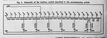
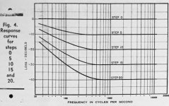
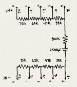
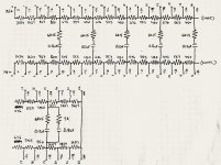
Attached below is a 70-year-old passive loudness circuit schematic for use with a 23/24 position stepped attenuator. The second attachment is a graph of the transfer characteristic for select steps of the attenuator. It is a single-ended design that I am attempting to convert to balanced for use with a 4-deck 24-step attenuator from Goldpoint. This attenuator will be sandwiched between two Neurochrome Universal Buffer modules operating in a balanced configuration. The final attachment is my proposed balanced revision of the first attachment, (showing just the first 5 positions).
I am asking for assistance in verifying that my proposed revision correctly maintains the transfer characteristic of the original circuit.
Thanks in advance.
I am asking for assistance in verifying that my proposed revision correctly maintains the transfer characteristic of the original circuit.
Thanks in advance.
Attachments
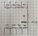
Should work the same. Double the shunt R, and halve the shunt C.
But I would scale down all of the circuit impedances by a factor of between ten and fifty,
whatever gives standard values. So smaller Rs, and larger Cs, and much less noise and parasitics.
The Neurochrome op amps can easily drive 10k and even less. This circuit was for tubes.
But I would scale down all of the circuit impedances by a factor of between ten and fifty,
whatever gives standard values. So smaller Rs, and larger Cs, and much less noise and parasitics.
The Neurochrome op amps can easily drive 10k and even less. This circuit was for tubes.
Last edited:
Interesting. I set a frequency of 1000Hz and converted all the elements into lumped impedances and did the ladder math; the attenuator presented an impedance of 12.7K. Unless my math was in error, isn’t that comparatively low for an attenuator? I’m more than happy to lower the noise and parasitics though, which is moreover why I am asking for help.
Thanks for the input, btw.
Thanks for the input, btw.
Last edited:
The first four resistors alone sum to around 200k. The total input impedance can't be lower than that,
although it does decrease substantially (starting at around 1M) at higher frequencies, esp over 1kHz.
Lab attenuators are more like 600R, but around 10k is fine for solid state audio.
although it does decrease substantially (starting at around 1M) at higher frequencies, esp over 1kHz.
Lab attenuators are more like 600R, but around 10k is fine for solid state audio.
Last edited:
Scaling by fifty looks good too. I'd probably do that, but either is much better than the original values.
I would guess that matching the Cs to all be the same (except for that last one)
would be more important than the exact value. Use 1% resistors and the values can be close.
I would guess that matching the Cs to all be the same (except for that last one)
would be more important than the exact value. Use 1% resistors and the values can be close.
Last edited:
There you go. Swap them around so the measured parallel totals are consistent.
You can also calculate the right scale factor to make the 0.115uF value exactly correct.
Using 1% resistors you can then still get close R values. That's often done with eq circuits, like for RIAA.
You can also calculate the right scale factor to make the 0.115uF value exactly correct.
Using 1% resistors you can then still get close R values. That's often done with eq circuits, like for RIAA.
Last edited:
Ray, Thank you again for your help. I was able to recalculate all the values in accordance with some precision capacitors for the EQ. It would still be nice to see the original calculated values that were rounded to form the basis for the original 70-year-old schematic but I think close enough is probably good enough. My scale factor ended up being 48.8. I still plan to post a revised schematic as soon as time allows.
Last edited:
I ordered the resistors already; 25ppm .1% 1/4W IRC RC55 series. In two instances I had to deviate from the schematic value by about 2% but in both those cases the resistors are matched in both phase legs and both channels (four resistors total). Otherwise, all the other values are within 1% of the schematic and due to the RC55 series tight tolerance, precisely matched to each other.
Very good, hope it works out well for you.
The Neurochrome buffer input impedance is listed as 48k, which should be good for your
impedance scaling factor. He lists no minimum load impedance for the first buffer.
Be sure to post some photos here when you are finished. You may have people asking
for your pc board files.
The Neurochrome buffer input impedance is listed as 48k, which should be good for your
impedance scaling factor. He lists no minimum load impedance for the first buffer.
Be sure to post some photos here when you are finished. You may have people asking
for your pc board files.
Last edited:

- Home
- Source & Line
- Analog Line Level
- Stepped attenuator conversion help (SE to BAL)