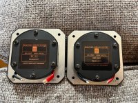
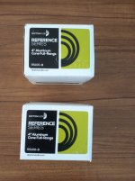
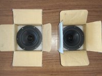
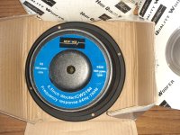
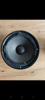
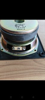
SB Acoustics Satori MR13TX-4 5" Textreme Midrange
MAY 12, 2024
I this post I test the
SB Acoustics Satori MR13TX-4 5" Textreme Midrange. This is midrange only version (MR) of the Mid-woofer (MW). This is a new product for 2024 and Mark from SB was kind enough to send me a pre-production sample by request. I have been looking for a good all-around 5" midrange for a variety of projects which I will get into at later blog posts. But for this blog post I want to focus on the the raw test data.
Features
- Advanced TeXtreme® cone
- Inverted soft low damping rubber surround
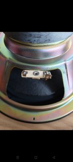
- Extended copper sleeve on pole piece
Manufacturer's Published Specification Sheet click
HERE.
The most interesting feature of this driver is the textreme diaphragm. I was curious to see just how high the breakup region is which should be well past the typical surround breakup.
Besides the diaphragm, how does the motor perform in terms of distortion? Let's find out!
Test Setup
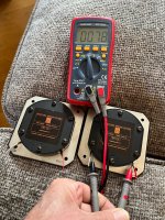
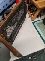
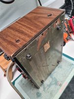
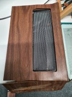
I decided to test the MR13TX-4 on my 90cm x 90cm IEC test baffle which in addition has a 8.6L sealed rear chamber measuring 13cm deep x 24cm wide x 24cm tall. I first measured the driver using a 30cm mic distance gated to 7cm where the first room reflection occurs. I then measured using a 5cm mic distance and spliced this ungated measurement in at 575Hz for the low frequency portion of the measurement. I applied 1/24dB octave smoothing for above 275Hz and 1/3 octave smoothing for below 275Hz. My measurement mic is an ACO Pacific 5012 running into a Scarlet Solo Mic Preamp.
Measurements
Let's start by looking at the manufacturer's published frequency response. High level we see an average sensitivity of 90dB through the midrange along with a breakup mode at 5.6kHz. The driver starts to become directional starting at 4kHz.
Showing the same zoomed in...
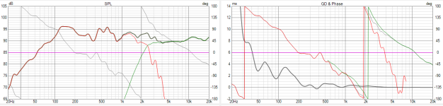
Below is the MR13TX-4 frequency response (red) with the impedance (green) overlay for reference. My measurements show a very linear response right up to breakup at 5.7kHz.
I then extended the same measurement out to 50kHz. It's interesting to note that we see output all the way up to 22kHz. This means two things...that the diaphragm is likely not breaking up and what we are seeing is simply surround breakup effecting the response, and secondly, that the motor has very low inductance. We can see this in the impedance sweep where there is very little inductive rise into the upper treble. Very interesting!
Moving the mic back from 30cm to 100cm to conduct off-axis is shown below. I measured at 0,15, & 30 off-axis. (SB measured at 15, 45, and 60). Below 500Hz I spliced in the ungated response of the same measurement. At the 1m mic position there is a slight bump in the response centered around 250Hz which is likely the result of the 90cm x 90cm test baffle.
With my results, directivity starts to narrow at 5kHz which is a little higher up than SB's off-axis results at 4kHz. So my results are actually a little better than published. This means that you can push your crossover point just a little higher if needed. Side note... This almost is a candidate for a wide band full range driver and appears to only need a super tweeter coming in at perhaps 8kHz?
Impedance
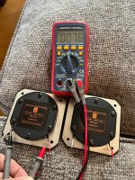
Looking at the impedance mounted in the 8.6L enclosure is shown below. This raises the FS from the factory 44Hz to 76Hz.
Time Domain
General comment on Time Domain
The time domain aspect shows the midrange driver's behavior after the signal has ended. The CSD plot looks at the behavoir in terms of time. We can see below that the 200Hz region takes around 3ms to fully die down below -25dB. The burst decay shows how many cycles are required for the signal to die down, which is a more relevant metric in terms of audibility. For example, the 200Hz region shows no issues in the Burst Decay, since 3ms is only a fraction of one cycle at the 200Hz frequency.
Another way of examining this result is to look at the 1kHz region on the CSD. We see that things die down quicker than 0.80ms for this frequency region. Since 1kHz takes 1ms to complete a full cycle, we can conclude that the woofer is able to die down within the time it takes for the woofer to complete one cycle.
Below is the CSD waterfall plot showing excellent behavior across it's usable bandwidth.
The burst decay is shown below, again an excellent result.
Distortion
I started with harmonic distortion placing the mic at 5cm from the diaphragm. The driver required 1.5V to produce 85dB at 1m. Distortion is below 0.10% with the exception of the resonant peak at 4.7kHz. Distortion is still very low even above this region. If the peak was EQ'd out then the distortion would in this region would also disappear.
Increasing the test SPL to 95dB requires 4.60V and we see a slight rise in H2 for the upper midrange. Otherwise H3 and H4 remain very low. (below 0.10%)
Intermodulation Distortion
I then produced a 12 band per octave test signal ranging from 200Hz to 20kHz which required 0.80V to produce the 85dB at 1m test signal. Generally we see around 65dB of dynamic range with surprising clarity in the upper treble as well. Again, if the peak at 4.7kHz is notched out with an EQ, we would see a very good result indeed.
Increasing the test SPL to 95dB required 2.73V and reduces dynamic range to a correlated amount of 55dB. Generally we don't see any stressing behavior at this elevated SPL.
Gedlee Distortion (Gm)
The Gm distortion is shown below for the 85dB and 95dB sweep. Gm uses a dual tone test signal and weights the distortion product (Gm) towards types of distortion that we find more offensive than others. Generally we can conclude from this result that the driver is slightly stressed in the upper midrange at the higher SPL, but the overall result is quite low.
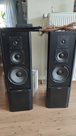
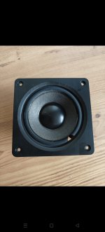
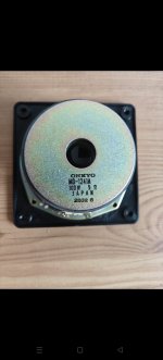
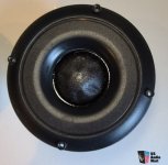
I tested the
MFC 5" woofer from SB (shown below) and the result was slightly higher Gm for both test SPL's. So the MRX woofer excels in Gm compared to SB's more affordable woofer models. Please note the result below should only be looked at below 2kHz since my quick test was conducted with the woofer mounted in the the 1159 stand mount 2-way speaker.
Conclusion
The MR13TX-4 is an exciting new product from the SB Acoustic Satori line up. The driver exhibits a very flat frequency response which indicates excellent time domain performance. The distortion profile is consistent in terms the H2,H3, & H4 ladder effect where we see H2 dominant at elevated SPL with H3 and H4 lower down respectively. I personally find this this ladder attribute remains a consistent metric to correlated sound quality. And lastly the Gm metric is very low when directly comparing against the more affordably priced MFC woofer from SB Acoustics. SB Acoustics has done its homework on producing an excellent dedicated 5" midrange.