To cite my favorite Audio Designer: "Audio design is perfectly mindless fun..."

Didn't intend to make this one; already made Babelfish F8, with few twists (just to justify Babelfish prefix), but that one destined to sit in folder
Some time ago, did found one interesting patent, sharing some basic virtues with Papa's F8, but nothing more interesting
As always, can't remember where tf I saved that pdf, couldn't find it, so few days ago tried to recollect my faint memory what was in .... and while I was thinking, had a napkin handy so I drew some sketches
Anyhow, everyone around (and his cat) is knowing basic principle of Papa's F8; few main virtues ( not both of these being in mentioned patent, feedback approach was in case) are single JFet in input stage, feedback loop containing JFet Rsource ( we know that already from F5 and few later ones) so that allowing that feedback loop is arranged as low impedance, so we can have majority of current feedback merits
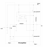
now, F8 simplified
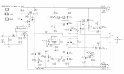
Consisted of two stages:
OS Iq set in Mu stage ( optothingie), while input JFet drain resistor being trimpot - allowing setting of output DC Offset; as always - Papa's careful routine is selected Idss of input JFet, so he know what resulting drain resistance is, thus OLG, thus resulting THD SPectra of entire amp
Ha - go clone it, if you can
///////////////////////////////////////////////////////
Edit on 16.08.2022. - final tests and schm values are in post #44, https://www.diyaudio.com/community/threads/scryer-or-how-f8-met-mighty-sissysit.388550/post-7098113
Didn't intend to make this one; already made Babelfish F8, with few twists (just to justify Babelfish prefix), but that one destined to sit in folder
Some time ago, did found one interesting patent, sharing some basic virtues with Papa's F8, but nothing more interesting
As always, can't remember where tf I saved that pdf, couldn't find it, so few days ago tried to recollect my faint memory what was in .... and while I was thinking, had a napkin handy so I drew some sketches
Anyhow, everyone around (and his cat) is knowing basic principle of Papa's F8; few main virtues ( not both of these being in mentioned patent, feedback approach was in case) are single JFet in input stage, feedback loop containing JFet Rsource ( we know that already from F5 and few later ones) so that allowing that feedback loop is arranged as low impedance, so we can have majority of current feedback merits
now, F8 simplified
Consisted of two stages:
- first one being common source P Jfet,
- second one being (also) common source Semisouth enhanced mode Mosfet , without source degeneration; loaded with Mu Follower stage made of plain vanilla IRFP N Mos
OS Iq set in Mu stage ( optothingie), while input JFet drain resistor being trimpot - allowing setting of output DC Offset; as always - Papa's careful routine is selected Idss of input JFet, so he know what resulting drain resistance is, thus OLG, thus resulting THD SPectra of entire amp
Ha - go clone it, if you can
///////////////////////////////////////////////////////
Edit on 16.08.2022. - final tests and schm values are in post #44, https://www.diyaudio.com/community/threads/scryer-or-how-f8-met-mighty-sissysit.388550/post-7098113
Attachments
Last edited:

You already know for my most recent Fetish ( one of many) ....... that's DEFiSIT OS stage
In fact, let's mention another one (fetish) - Square Law OS
As I said - I made Babelfish F8, so it wasn't interesting - first - that's Pa's recent, second - hard to improve already max. simplified Demonstration of Force ( hehe, I did it) and - third - I already made it, so can't doing it again
Logically - when I felt urge, it unavoidably ended in something completely different
So, I meant to use one JFet - low impedance feedback net approach, minimum number of stages ........ and (Fetish!) what else than what I already have - ether DEFiSIT OS ( read - SissySIT) or Mos Square Law OS ( read - Babelfish M25)
Let's start with napkin drawing:
JFet having voltage umbrella (cascode), just for good measure and because I'm Chicken
reason - why bjt in second stage and not (Papa's usual) T0220 MOS - resulting swing is greater if you not loose 4V for Mos Ugs; just think - 4V mos, 0V65 bjt
In fact, let's mention another one (fetish) - Square Law OS
As I said - I made Babelfish F8, so it wasn't interesting - first - that's Pa's recent, second - hard to improve already max. simplified Demonstration of Force ( hehe, I did it) and - third - I already made it, so can't doing it again
Logically - when I felt urge, it unavoidably ended in something completely different
So, I meant to use one JFet - low impedance feedback net approach, minimum number of stages ........ and (Fetish!) what else than what I already have - ether DEFiSIT OS ( read - SissySIT) or Mos Square Law OS ( read - Babelfish M25)
Let's start with napkin drawing:
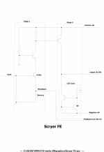
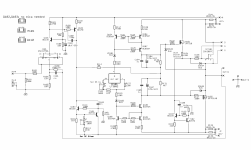
- Two stages:
- first one being common source N Channel JFet ( so same-same as in F8),
- second one being common emiter BJT ( having emiter degeneration, let's keep OLG sane), loaded with (ring of two) CCS
JFet having voltage umbrella (cascode), just for good measure and because I'm Chicken
reason - why bjt in second stage and not (Papa's usual) T0220 MOS - resulting swing is greater if you not loose 4V for Mos Ugs; just think - 4V mos, 0V65 bjt
Attachments
Last edited:
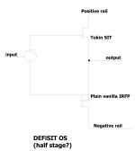
So, I already have 2 stages and can't go without OS; luckily DEFiSIT OS is follower (even if special one) and Pa taught us that one must always think ( aloud) in own benefit, so let's declare that as 1/2 Stage
Result - eat my liver, I made it with just 1/2 stages more than Pa's
DEFiSIT OS, simplified
Result - eat my liver, I made it with just 1/2 stages more than Pa's
DEFiSIT OS, simplified
Attachments
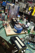
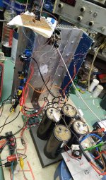
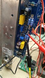
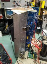
As I already had SissySIT (42) on my small T-Bed, happily singing all day long in my WShop, it was logical to remove jumper, desolder Cinemag out , place Ikebana raster pcb on top and solder few wires and fire it up
pair of 2SK170BL is acting as one 2SK2145BL
boring; it was working from hop, all I needed to do was to set output DC Offset ......
as you see from pics, but not wrong to say it :
outputs are THF51 and IRFP9140
Iq 1A85
Rails +/-23
pair of 2SK170BL is acting as one 2SK2145BL
boring; it was working from hop, all I needed to do was to set output DC Offset ......
as you see from pics, but not wrong to say it :
outputs are THF51 and IRFP9140
Iq 1A85
Rails +/-23
Attachments
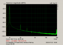
Proof is in Da Pooding, 1/2
Load 8R
400mV in for 2V83 out; all RMS, so 1W@8R; calc sez gain is 7.075V/V, 17db
Load 8R
400mV in for 2V83 out; all RMS, so 1W@8R; calc sez gain is 7.075V/V, 17db
Attachments

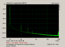
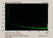
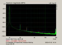
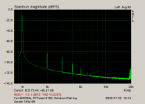
Proof is in Da Pooding, 2/2
Load 4R
285mV in for 2V0 out; all RMS, so 1W@4R; calc sez gain is 7.017V/V, 16.9db
2nd is negative phase
Load 4R
285mV in for 2V0 out; all RMS, so 1W@4R; calc sez gain is 7.017V/V, 16.9db
2nd is negative phase
Attachments
-
 Scryer 1W 4R.png7.4 KB · Views: 223
 -
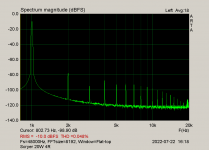
 Scryer 5W 4R.png33.4 KB · Views: 226
 -
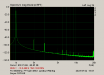
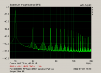
 Scryer 10W 4R.png33.6 KB · Views: 223
 -
 Scryer 15W 4R.png7.1 KB · Views: 226
 -
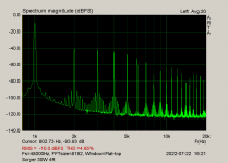
 Scryer 20W 4R.png35.9 KB · Views: 228
 -
 Scryer 25W 4R.png43.9 KB · Views: 223
 -
 Scryer 30W 4R.png45.6 KB · Views: 198
 -
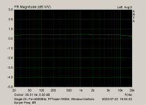
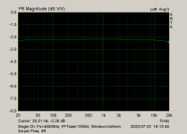 Scryer Freq. 4R.png46 KB · Views: 174
 -
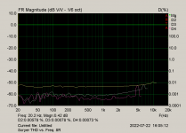
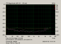 Scryer THD vs. Freq. 4R.png50.4 KB · Views: 227
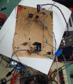
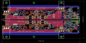
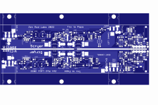
Those napkins I'm using are usually of good quality, so I was confident enough to make some files even before I started soldering Ikebana pcb
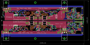
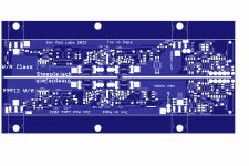
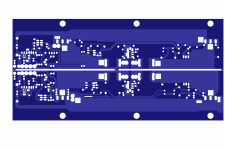
so, pcb is trivial - few edits of existing one, and some laaaazy work to put few FE parts in place of removed input buffer + autoformer
I even shorted pcb, comparing to SissySIT

so, pcb is trivial - few edits of existing one, and some laaaazy work to put few FE parts in place of removed input buffer + autoformer
I even shorted pcb, comparing to SissySIT
Attachments

Steeplejack, just a Teaser
practically same everything ...... except both OS parts being plain vanilla IRFP
upper one can be Schaded or not ( thus drawn usual combo of small CCS down and DN2540 up, as follower/level shifter)
Plethora of Pinjatas OS arrangement, to be more precise
didn't tried this one, but I know it'll work
in time, both Scryer and Steeplejack pcbs will arrive, and will post usual ( measurements) functionality confirmation
Attachments
Last edited:

@von Ah
rail - anything you read between 22Vdc and 25Vdc is nominally 24Vdc
simple - Pa is always showing 24Vdc as result of having 18Vac secondaries
in realm of small A Class amps, with common used diode bridges and filtering, in most case that's ending as 22V5 to 23Vdc rail, sorta 1.25 multiplication factor, when going to compute AC to DC
Donut on my T-Bed is having slightly more than 18Vac per secondary, thus the difference ...... irrelevant in entire story
....Also, would ACP+ have enough cojones to drive this one (2087C variety)?
I forgot to reply specifically ......
post #5:
"Load 8R
400mV in for 2V83 out; all RMS, so 1W@8R; calc sez gain is 7.075V/V, 17db"
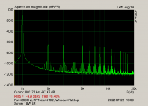
full blast - as shown in graphs, is 18W@8R
18W ..... as P=(Urms^2)/Rload, it computes that RMS voltage for 18W is 12V
divided with 7.075V/V, sez that you need 1V67rms for full blast
practically - any today's source (line level practically being 2Vrms) is good to drive it to full blast, taking in account amp's Rin of 100K (value of R101)
though, I prefer to have some sort of line stage in between, even without gain per se
be it ACP or any other, by your choice
now - these tests made with THF51 in output; slight difference*** exist with 2SK2087, but count that gain should be same
*** visit thread linked in post #4
- Home
- Amplifiers
- Pass Labs
- Scryer ... or how F8 met Mighty SissySIT