MTX JH15001

Wondering if anyone can lead me to a matching potentiometer, one of the c103s just keeps spinning and doesn't have a minimum and maximum stopping point. Also seems to be causing issues. I have some similar but most of what i have are 6 pin and not 7 like these and also most of mine have a longer shaft.

Attachments

  • 423599782_377290728458947_8259867823727770372_n.jpg
    423599782_377290728458947_8259867823727770372_n.jpg
    128.4 KB · Views: 47
  • 430938422_3594312317496535_5502435756453279047_n.jpg
    430938422_3594312317496535_5502435756453279047_n.jpg
    152.1 KB · Views: 44
  • 430992229_1434080130532117_6876608525530938391_n.jpg
    430992229_1434080130532117_6876608525530938391_n.jpg
    144 KB · Views: 49
  • 431052638_1425249581408223_3226384140771487904_n.jpg
    431052638_1425249581408223_3226384140771487904_n.jpg
    117.7 KB · Views: 49

Drivers for Fostex P1000-E

Hi,

I was looking for a fullrange for my desktop nearfield listening with a tube amp and didn't find many choices (none actually), but found the Fostex P1000-E enclosure. It says it's meant for Fostex P1000K, but search suggests some FE103 variations were used with success, all of which are discontinued and hard to get. I was wondering if the current FE103NV (which has a diferent Recommended Enclosure) would work fine in this enclosure or different specs make it not compatible? Just thinking a P1000K is too low end of a driver judging by the price.

No knowledge in the field, I am a consumer 🙂

JVC ZLX31 digital coax out to S.M.S.L. A300 USB in (no coax in connector)

2024-03-06 I'm trying to connect JVC XL-z431 coax out to my s.m.s.l. a300. The cable is plugged in both ends, and I have selected usb in, because there is no coax in on the a300. The coax cable from the xlz431 goes into a DSD TECH SH-AU01A USB to Coaxial Audio Adapter. Its output (usb) is pluggged into the a300. I get no sound. Is there any reason to doubt this connection adapter? or doubt the coax out on the xlz431? I need help to make this connection work. I love the old cd player transport; I'm just trying to bypass the 35-yr-old dac and use the new one in the a300.

Monoblock Tubelab SSE

Looking for info on what I need to change component wise, what components I can leave out to make a single channel SSE.

For the power supply transformer, can I halve the current ratings on each of the windings (700 to 750 VCT @ 175 mA DC output --> 88 mA, 5 VAC at at least 2 amps --> 1A or for 5R4 rectifier 3 amps --> 1.5A, The main filament winding should be 6.3 VAC at at least 5 amps --> 2.5A)?

At the moment I would plan to use a Sovtek 5AR4 rectifier, 12AT7 preamp tube, Sovtek 6550WE output tube, and for the output transformer an Edcor XSE15-8-5k.

From 3 to 3.5 or 4 ways

I’ve decided to give up on a 3-way build. The crossover for dual 10” woofers to a 2” dome midrange is employed around 450-650 Hz. I found the woofer’s best performance is achieved when the low-pass is only set at below 300Hz. But that will introduce a large gap between woofers and the dome midrange because the dome midrange cannot go as low as 300Hz. I realize that there are two options for me now:

1) go for 3.5 ways, let one woofer play lower midrange continuously from the dome midrange and let another woofer be as a subwoofer, having low crossover point i.e. below 300Hz.
2) go for 4 ways, sell a pair of 10” woofers for a pair of 6-8” woofers. Use the remaining 10” woofers as subwoofers crossed at below 300Hz as well.

Which one is more interesting?

Cary SLA-30 - Understanding schematics

Howdy gang!

I've got a Cary SLA-30 from the early 90s. The schematic is barely readable (at least to me) and I'm trying to copy it all out into Kicad so that it's more usable, and also, so I can eventually tackle the rev 1 version that changes the bias, but I'd like to get how it's currently built (rev 0) drawn out properly.

My issue is simply trying to understand the original schematic because of how it's drawn, and re-drawing it in Kicad. If anyone could look at this and see if I'm making any terrible errors, or if anyone has any general commentary, that would be great!

Here's the original, and the translation into Kicad that I'm working on.
Edit: Added internal picture

Attachments

  • asdfg.png
    asdfg.png
    97 KB · Views: 462
  • asdfwefw.png
    asdfwefw.png
    91.4 KB · Views: 406
  • unnamed (1).jpg
    unnamed (1).jpg
    651.1 KB · Views: 385

Making fun of my younger self: "The Brief Confessions of a Former Mahler Unbeliever" or, “My Road to Mahler”

After my massive, 4,000-word article about Jerry Bruck's "experimental" Horenstein/LSO Mahler 3 recording, I was concerned that people might think I was too serious. So, some of you might get a chuckle out of my memoir about how the music of Gustav Mahler bedeviled my love life while I was in college.

ciao,

john

Tantalum Caps In DC Servo Circuit?

How are you all doing?
I for one am in need of your expertise.

Initially I planned to use chunky SMD ceramic caps but then i learned those are darn voltage dependent (unless C0G but those >1uF just barely exist). I dont want to make PCB space for two film caps so that leaves Electrolytic and... Tantalum?

Either would allow C11&12 to be 10uF easily fitting in a 2220 sized space. Also keeping in mind C12 can be diode clamped to ground so the voltage rating can be low. Additionally a small value C0G ceramic could be use to bypass C11&12.

This particular low ESR Tantalum cap range seems reasonable for audio frequencies:
https://ksim3.kemet.com/capacitor-simulation?pn=T495C107K006ATE150&disty=mouser

DC servo Implementation:
Schermafbeelding 2024-03-09 033309.png


Of course tantalum caps are polar, so two should be placed in series, but since the Vswing will only be +-0.7V cant we just use the one?

Dabble with electrolithic, tantalum or other types, or go for the huge film caps anyway?

Feel free to share your opinions

Much thanks and cheers,

Ruben

Cross over help please

Ok so I ordered the Dayton audio br1 kit and I have messed up the crossovers I have never done them before and like an idiot I clipped the leads down and glued the to the inclosure without checking it first. Is there a pre assembled cross over that I could use that would sound good or a cross over design that someone would be kind enough to give me detailed instructions on. I would greatly appreciate it, wouldn’t mind to cash app somebody a few bucks if need be. Thanks in advance

FINALLY, getting Mission 737R just for the woofers, why?

Hey everyone. So naw my Mission 770
from back in the day will have new woffers. The tweeters, i will have a go at cleaning out old ferrofluid if not capable of doing this well suggestions are welcome. A full clean up of the cabs
Age related scuffs nothing deep.
How shall I go forward with my new task? I've had a look inside and the foam in good nik, very dense and firm. Interior panels have got about 5mm thick black dampening pannels stuck on. I need help on
1 best way to make exterior shine
2 the tweeters, clean or replace
3 crossover back into spec
4 interior wireing change for high quality
5 your suggestions and experience
Thanks

Onkyo M-505 update

Hi again. I was finally able to replace all of the electrolytics in this piece of crap only to discover that it still produces exactly the same bad cap smell.

I suffered a near fatal heart attack a few weeks ago, and had a friend help me finish it yesterday.

I don't know what else could be producing the smell. The amp shows no sign of corrosion, yet it smells like burning rust.

It also runs cool all the time, so no problems with overheating.

I am at my wits end here.

Antec Tube Transformer products.

As anyone used the tube-related products from Antec? PS transformers and chokes? What's the word? Any good? Has anyone built anything using those?
I am not sure toroidal is the right type of core for OPT, none of the majors OPT manu are doing that, and the high freq response seems to reflect that. Not sure about chokes application.
Another issue I have with PS transformer from Antec is the 115V primary. I really wish they went to 120V, as the 4% higher voltage is not ideal and elevates the output voltage. That is an annoyance in itself.
The prices are an absolute bargain though..

Apologies if this topic has been discussed before.

THX 789 Mods

Say hello to my newest victim.


So far, I’ve replaced the stock power supply with a Jameco linear regulated power supply and the very crappy pot with a resistor ladder attenuator.

Currently, I’ve removed the relay closest to the pot, to make room for the new pot, but to avoid burning down my house can anyone confirm I’m bypassing it correctly?

Below is the pinout of the relay:


Using the above I'm guessing I just need to short these 2 pins on either side


The thing is the 789 has relay's up the wazoo. I figure this is the reason I can't check if I'm connecting the right pins, because the signal from the RCA jacks to this relay isn't actually connected, from another relay I'm assuming, until this thing powers on.

Am I doing this right? I've desoldered the relay and am just waiting for the go ahead to short pin 2 to pin 4 and pin 9 to pin 7. I know for sure that pin 2 and pin 9 are shorted to the attenuator's input for their respective channel.

Lastly, near the 24V input voltage there is a rail splitter to two 12v rails and the original pcb has space for two smoothing capacitors. I’m willing to bet they were removed due to cost constraints. Would there be any benefit to adding these back in, and what value capacitors I should put in?

Thanks!

Convert Balanced Line Level Signal To Unbalanced Amp Input (Class D Module)

I'm looking at building an amplifier from Class D modules (ICEpower). I am using balanced XLR cables everywhere in my system, so would like to build this amp with XLR input, even if the amp is not designed for balanced input.

How much of a problem is this? I thought I should be able to connect the ground pin to the chassis ground, and add a resistor between the XLR and the amp input? Or is there more to it? Or a potentiometer? I don't the correct value at the moment.

What Pass Labs amp is this?

I am NOT a DIYer so it may be a stupid question. The seller doesn’t know what amp this but he says it is supposed to be a Pass Labs circuit. He bought it from someone.

Can you tell what model it is? And how well/cleaned it is made? Looks neat to me.

This is also what he mentions about the specs but I don’t know how accurate it is.

Very nice sounding 30wpc class Internal working voltage: two groups of independent double 35V DC


Pure Class A output power:

26W*2 8 ohm speaker

30W*2 4 ohm speaker


SNR: 108db

Attachments

  • IMG_5555.png
    IMG_5555.png
    422.9 KB · Views: 229

Please help with my first build from scratch- MTM

Hello all…been lurking for a few months…this place has been a gold mine of info. Thanks!
So I just finished my first kit build (Sambas) and I’ve got the DIY bug. I would like to build some MTM bookshelf speakers. Definitely LR’s and hopefully a center if that works.

Drivers:
Woofers: Dynavox LW6004HR-N
https://www.parts-express.com/Dynavox-LW6004HR-N-6-1-2-Honeycomb-Cone-Woofer-295-626


I really like these for aesthetic reasons and due to the manufacturer reputation and positive reviews.

Tweeter:
I wanted to use Dynavox tweeters as well but PE only has one model of their tweeter and it’s on clearance with only one in stock.

So I tried to get close to the woofer sensitivity and landed on these:
Morel MD 29
https://www.parts-express.com/Morel-MDT-29-1-1-8-Soft-Dome-Tweeter-277-010

Encloser: as far as material I haven’t gotten that far. I know I want large bookshelf that will go on stands.

Crossover: no clue! Hopefully I can get some help here 🙂

Questions:

1. Do my choices seem like a good idea?

2. How do I calculate box volume when using two woofers? Any help would be greatly appreciated

3. I’m hoping I can build a third for center channel…that’s doable right?

Thank you in advance!!! I’m not sure how this will develop but I’m determined to see this through till completion.

Polypropylene Capacitors, Mundorf, Audyn, Jantzen UK

I'm selling all my capacitors for half price, plus postage (usually around £4).
Let's start at the most expensive, and my favourite capacitors. If only I could design a speaker around a single 2.7uF capacitor. There would be no way in hell I'd sell these. Not cheap, but by far the most natural sound.
2 x Audyn True Copper Max 2.7uF 630v - £260 plus £3.29 postage (would be £520! plus postage through hificollective) = £263.29

XK4myAP.jpeg


2 x Mundorf MCap Supreme EVO Aluminium Oil 33uF 600VDC - £105 plus £3.29 postage (£210 hificollective) = £108.28
a2rqjI0.jpeg


2 x Audyn True Copper Max 0.33uF 630v - £78 plus £3.29 postage (£157 hificollective) = £81.29
WAHQ46n.jpeg


2 x Mundorf MCap Supreme EVO Aluminium Oil 5.6uF 800VDC - £48 plus £3.29 postage (£96 hificollective) = £51.29
vdXGyXN.jpeg

XLR socket standard - when to use male/female? (source, amp, speakers et)

Hi

I’m building a little hifi setup that’ll use XLR interconnects and speaker cabling. This is just for aesthetics but It’ll be balanced where applicable .

What is the rule of thumb for when to use a male or female SOCKET? I real that it’s:
Outputs = Male
Inputs = Female
So…
Sources: (media player): male socket,
Preamp: Inputs: all female sockets; Output to amp: male sockets
Amp input: female
Does this carry over to speaker cabling:
Output from amp: male
Speaker: input female

Correct?
Thank you

Perlisten's mid/tweeter array

Hi!

Does anybody have more info on the driver array Perlisten uses?
How does it work? What type of crossover and frequencies do they use?

I think the drivers might be Seas custom units, some of the components look like Seas made, but I am not shure.

If one would like to try it out DIY style, how would one go about? What drivers to use?

In my simple mind the use of such small drivers and membranes for the mid register could possibly be a superior sounding solution.

Would like to know what there is to know about this configuration, especially when it comes to crossovers used.

I stupidly connected my 65v, 500w HBP SMPS to my IRS2092 amplifier board without draining the capacitors and blew my SMPS the amp ok for new SMPS?

So I couldn't figure out why my amp sounded very bad until I finally saw the (short -120v) and (open-240v) selector connection holes on the board. I connected a jumper and then tested it, with amp disconnected because that made it easier to inspect with my multi-meter and I finally had my full voltages, 72v, not the 38v I had before. In my moment of joy I rushed and I forgot about the capacitors. When I connected the smps to the amp the connection arced loudly and with a blueish white color. The hbp500 smps had a blown mosfet, fuse, rectifier, and driver. I've ordered another smps because it'll be nearly a month to get most of the replacement parts that were blown and I can't find the driver part numbers on the power supply because they have obliterated the part#'s anyways. I cannot afford to pay another $40 for a third smps I really need to know if the amp could blow my new smps and how I can test it if it can. I do not have an oscilloscope yet only a multi-meter right now. Thanks in advance.

Attachments

  • 16746185780616602434270347793657.jpg
    16746185780616602434270347793657.jpg
    396.4 KB · Views: 228
  • 16746186498951579519548375127502.jpg
    16746186498951579519548375127502.jpg
    375.3 KB · Views: 231

For Sale HiFi2000 Galaxy Chassis and Parts

Sold out!

- Galaxy GX383 chassis (2U, 330x230mm, iron top and bottom, 3mm silver front panel, sealed)

- Galaxy GX387 chassis (2U, 330x170mm, iron bottom, 3mm black front panel) + top substitution with 2mm aluminium cover GALAXY 347-387 without any hole (unpacked but unused)

- Rear panel Galaxy 343-347-348 (1U, 40x330mm, 3mm black, sealed)

- Additional 2mm aluminium cover GALAXY 347-387 (330x170mm) without any hole (Sealed)

- Front panel Galaxy 343-347-348 (1U, 44x334mm, 3mm silver, sealed)

- Front panel Galaxy 383-387-388 (2U, 84x334mm, 3 mm black, drilled but unused). Features holes for Alps RK27 pot centrally and 6mm hole at 50mm from the border to be used with a switch or led holder (can provide it in black or chromed)

- Rear panel Galaxy 343-347-348 (1U, 40x330mm, 3mm black, drilled and used). It is this very panel and I can provide it with new RCA connectors and IEC filtered socket

- Large and small black knobs (Not in picture. Sealed)

Attachments

  • 2024-03-08 17.22.20.jpg
    2024-03-08 17.22.20.jpg
    535.6 KB · Views: 85
  • 2024-03-08 17.40.35.jpg
    2024-03-08 17.40.35.jpg
    780.9 KB · Views: 73
  • 2024-03-08 17.44.44.jpg
    2024-03-08 17.44.44.jpg
    543 KB · Views: 74
  • 2024-03-08 17.45.57.jpg
    2024-03-08 17.45.57.jpg
    635.1 KB · Views: 82

Novation Launch Control XL Mk2 WEIRD BEHAVIOR....please HELP!!!

First 3 faders don't work.....sending midi CC messages even not touching them. I desoldered first one just to check....MIDI OX sending values even without it. Strange thing is that 3 rotary pots above the first 3 faders act like volume control and they supposed to be pan knobs, all the rest works fine. IC on PCB 74HC4052d, 74HC1640 .Brain is ARM STM32F103. Which chip controls midi input? Even when i change the midi channel and midi CC number for the first 3 channels it acts the same.....HELP BROTHERS!

video https://streamable.com/a6cx3l

Attachments

  • 0-02-05-e292d7aa4f1341b8c860f252eedc3abf66819aac3dde2754f087215a2b3d00d0_c4aac614b5fba813.jpg
    0-02-05-e292d7aa4f1341b8c860f252eedc3abf66819aac3dde2754f087215a2b3d00d0_c4aac614b5fba813.jpg
    218.9 KB · Views: 148

What do you need to do to damage a DCX464?

I have just had the strangest experience with my pair of DCX464. I bought them new, they sat in a box for around a year and then I took one out and did a few sweeps at living room SPL level to measure the FR and impedance with a horn. I put it back to the box and pulled it out another 9 months later. Again, I did a few sweeps with a horn and without it at comfortable levels - I would say 95 dB/m absolutely maximum, more probably less - since I did measure mostly a few cm from the mouth. I used the log chirp from Clio Pocket and a solid state amp I am normally using, which has no problems at all (except for a little noise and hum, which is another story). This time I took out both - measuring one on a horn and one without it. I got some strange results, so I did more measurements swapping the drivers, etc. The unused coil was always shorted or connected to the other channel of the test amplifier.

The drivers were sent back to BC for investigation since one unit had suspicious measurements on MF FR and Z, the other unit had suspicious measurements on the HF unit. They took the drivers apart and the membranes were smashed (they say, I have not seen any evidence of that). They suspect severe overload of the drivers (which has never happened!), but were kind enough to replace all the membranes free of charge.

I wonder what does one need to do to destroy the membranes of the drivers (all four!) - what voltage/frequency can damage these without a horn and on a 300 Hz horn? I did nothing but the FR sweeps. I have measured compression drivers like this for many years and none was destroyed by that (even the tiny 1" compression tweeters). I am puzzled, what could have happened? Either I have destroyed them with the (relatively silent) sweeps or they must have been damaged before I bought them new in a factory sealed box.

Question: How can I test this motor to see if it is good or bad?

I have a Pro-Ject Classic SB turntable that fails to power on. I have replaced the Speed Control Board and the Power Board and still no luck. The last thing to try is this motor, but i'd like to find a simple way to determine if it is good or bad. is it possible to use a multi-meter to do this or is there another method I could use to get power to it without the speed board and power board? Thanks for your help!


50E33BCB-27E9-4914-B5E4-82D07562F479_1_105_c.jpeg


3B0FB1ED-D978-479F-AD67-DC928B30EE1D_1_105_c.jpeg

Adding a second driver in series

If I want to add a second driver (the same driver, in series) to a design, would I have to double the effective cabinet volume for the same response? I haven't quite got to grips with designing a cabinet with multiple drivers that share the cabinet volume. Is it simply additive, does one driver bound the others (where there are a mix of ranged drivers) or is there a more complex interaction.

What are the pros and cons of single 12in vs 2x8in as woofers in a 3way?

I am wondering, what are the pros and cons of single 12inch vs 2x8inch used as woofer in a 3way?

Cons area variances between them is around 10%, 8 inch take less space and is more WAF friendly.

12 inch makes big box.

Both can go deep simiraly, a lot of pro 12 inchers even can't go below 40Hz...
But there are some who can 😉

Just thinking about my future build, and if we would put aside form/space and higher efficiency in pro drivers, than...

What's the reason to buy single 12inch vs 2 8inch to act as woofers in 3 way?

UMS compatible TO3 mounting brackets for 2016 VFET amp and 1 pair 2sj28s

New, never used, UMS compatible TO3 mounting brackets for 2017 VFET amp. These were for the original VFet amp kits from 2017.
$120 including USPS flat rate box to CONUS.

1 pair Sony 2sj28 KF-33 from CircuitDIY Acronman
$225 including USPS flat rate box to CONUS

Both Brackets and 2sj28s combined for $300 shipped USPS flat rate to CONUS

PP F&F

DIY Sony VFET pt 1

- SOLD -

Selling this VFET amp from the original/first lottery. As everybody knows, designed by Nelson Pass. Beautiful sound! 🙂
The amp is in perfect condition. For the wiring I opted to use Duelund cable - which I've found to sound awesome.

The kit cost 650usd when sent to Finland - plus the Duelund cable. So looking for 700 euro. Buyer pays shipping. Will be packed to withstand UPS handlers.

- Jukka

Attachments

  • IMG_0281.jpg
    IMG_0281.jpg
    795.3 KB · Views: 111
  • IMG_0277.jpg
    IMG_0277.jpg
    625.4 KB · Views: 121
  • IMG_0274.jpg
    IMG_0274.jpg
    760.2 KB · Views: 115

Noise from OPT

Hello friends, I'm still learning and asking.

Login to view embedded media
Is this noise that comes out of the opt normal? Is it oscillating?
I am using a square wave at 1khz, 1vpp.
I tried it with sine wave and at some frequencies it does the same thing, is it something bad?

I have it connected with a load, the oscilloscope and a function generator.


Another question that I was looking for in the forum and I didn't know how to search for it.

Thank you for your time and wisdom.

What can I use as wiring

Hey, I am a complete newbie and currently planning my first project.
I want to build a simple A/B switch with volume control. I found plans and ordered parts, now the only thing missing are the wires. On the website I ordered my parts I only found "audio cable" but only on 100m rolls, wich is way too much.
Can I use cables from old/broken audio equipment or XLR cables?
If not, what do I have to search for?
Greetings

Any alternatives to FPGraphTracer?

Hi all,

This is my first post. I am trying to get started with crossover design in XSim and saw in several places that you can extract the frd and zma files from the manufacturer's datasheet with the FPGraphTracer tool. All of the links to that download pull up a 404 Not Found webpage. I was wondering if there are any alternatives to that tool or if anyone has any other means of downloading it.

Thanks!
Colin

For Sale Acoustic Research AR-XA Turntable

This is An Acoustic Research AR-XA in fantastic condition, plays and sounds fantastic.
Solid Walnut plinth,
It has a lightly use Grado Black cartridge on it.
Has many upgrades including Tonearm Sapphire bearings,new Springs, new Litz wiring, RCA back panel jacks,and many more listed on the invoice picture on the listing.
Local pickup only Huntersville, NC area
$600

Attachments

  • IMG_6713.jpeg
    IMG_6713.jpeg
    397 KB · Views: 207
  • IMG_6719.jpeg
    IMG_6719.jpeg
    344.7 KB · Views: 249

Paramuse: Album-oriented music server/web app

This is a little bit of software I wrote to meet my particular preferences for a music server/player:
  • Play random albums (rather than individual tracks).
  • Run locally (no dependence on 3rd parties, or an internet connection at all)
  • Use a normal web browser as a client (so it works on any device, including phones, with no need to install anything).
  • Support ReplayGain (so I don't have to keep adjusting the volume up and down, especially for new vs. old recordings).
  • Glowy neon and LED bits (because why not).

I released it to the public in case anyone else finds it useful, but bear in mind that since I wrote it for myself, I didn't put any effort into making it easy to use, or any thought into what features other people might want. Also note that it has no auth, so don't expose it directly to the internet unless you want everyone on Earth to have access to your music collection.

Here's what the client looks like in a desktop browser:
Desktop.png


And in a phone browser:
Phone.jpg


And a short video clip of the spectrum analyser:


To run the server you need to
  • Install both the .NET 6.0 Runtime (or Desktop Runtime) and the ASP.NET Core Runtime.
  • Extract Paramuse_1.1.zip to a folder somewhere.
  • Edit appsettings.json and set BasePath to where your music is stored.
  • Run Paramuse.exe
  • Wait a while for it to scan all the music (should take just a few seconds with an SSD. It might take a minute or two if the music is stored somewhere slower). Only MP3, OGG and FLAC are supported.

It should work on Windows, Linux and Mac, but I've only tested it on Windows. It should also have relatively low hardware requirements, but I haven't experimented with that either.

Once the server is running, you can connect to it with a web browser on port 8080, e.g. if the browser and server are on the same machine, this will be http://localhost:8080. If you want to connect to it from a different machine then you'll need to find the server's local IP address and use that instead of "localhost". You need a newish browser (current Firefox and Chrome work; old phone browsers may not).

The client has just the bare minimum needed to play albums. In the box at the top it shows details of the currently playing track, with some controls (prev/next track, play/pause, shuffle, a timeline, and a volume control). There's also a spectrum analyser just because I love those.

Underneath is a list of every album that was detected. All audio files in the same folder are classed as a single album, so it only works properly if you organize your music well. The actual names will be read from ID3 tags where possible. It will also get album art from ID3 tags, or from separate image files if either are present. There's a play button next to each album to play that album directly. You can also click on the album to expand it to list all the tracks it contains.

There's source code available on GitHub or my own website.

Attachments

irs2092 in parallel on one +-65V source

Hi all
I'd like to use 4 irs2092 in parallel on one +-65V (1500W) source, like I saw it in several youtube videos
(all components from aliexpress)

While with only one irs2092 everything works fine, problems arise by adding further irs2092 in parallel.

Problem:
impulses at loudspeakers with 2Hz to about 10Hz randomly (rally noisy loud spikes)

so there is a kind of interaction of these amps , ..no idea what is the reason

I already tried:
  • changing the audio input signal (different Bluetooth receiver & dsp boards) -> no impact
  • different combination of irs2092 (to check if any of these is particularly damaged) -> any mix gives similar result (->no single defect of one amp)
  • R13 is 101 (not sure if this plays a role as described in other posts)

I only have basic electronic and soldering skills, and would be thankful for your support.
best regards

Attachments

  • 20240307_203423[1].jpg
    20240307_203423[1].jpg
    473.1 KB · Views: 104
  • 20240305_222145[1].jpg
    20240305_222145[1].jpg
    331.8 KB · Views: 94

Tweaking commercial speakers, need help

I've been tweaking crossover networks of ADS L1590/2 speakers.

First, let me explain the reason for this modification. The sound character of these speakers tends to lean towards bright, opened midrange and, some people describe it as a little bass-shy. For me, I consider them to be too pale though. The objective is to gain more bass and tame the midrange.

Since each speaker is about 42kg in weight, I didn't pick them to the measurement. I just use simulation of the crossover instead, along with reading "tweaking crossovers without measurement" thread.

Okay, here is the simulation result of the original crossover. As you can see, there's definitely a spike on the upper midrange, around 1.5-3.5 kHz, as depicted in red circle.

original.png

I started tweaking by adding single resistors to tweeter and midrange circuits and lowering low-pass filter of the woofers. This is aimed to reduce midrange and tweeter levels.

Next, I move to tame the midrange spike. I performed by adjusting the low-pass's capacitor of the midrange. From 15uF to 37uF, the response curve has now become flat.

modified.png

Here I have some questions.

1) According to the online calculator, the original 15uF and 0.4mH filter gives Q of 1.162, whereas the modified 37uF and 0.4mH gives Q of 1.825. Both Qs are considered to be quite high. So, will it cause any problems, e.g., impedance issue?

2) Will it cause problem from using the 37uF for low-pass of the midrange in which it's larger than 33uF of the high-pass's section?

Attachments

  • original Q.png
    original Q.png
    5.7 KB · Views: 49
  • modified Q.png
    modified Q.png
    5.7 KB · Views: 59
  • Like
Reactions: Guerilla

Dayton 7"Mid woofers and 1" dome tweeters

I have FOUR (4) Dayton Audio RS180-8 7" Reference Woofer. asking $50 each, $100 per pair plus shipping or buy all four for $200 and get free shipping in the USA

I have TWO (2) Dayton Audio RST28A-4 1-1/8" Reference Series Aluminum Dome Tweeter 4 Ohm
asking $50 per pair plus shipping.
these were in a custom set of studio monitor speakers that were finished but never used.

or buy ALL for $250 with free shipping in the USA. may consider offers.

Attachments

  • 20240109_190715.jpg
    20240109_190715.jpg
    332.5 KB · Views: 56
  • 20240109_190717.jpg
    20240109_190717.jpg
    254.5 KB · Views: 50
  • 20240109_190726.jpg
    20240109_190726.jpg
    253.6 KB · Views: 56
  • 20240109_190730.jpg
    20240109_190730.jpg
    215.1 KB · Views: 52
  • 20240109_190732.jpg
    20240109_190732.jpg
    251.1 KB · Views: 48
  • 20240109_190736.jpg
    20240109_190736.jpg
    226.4 KB · Views: 55

For Sale "WHAMMY" Pass DIY headphone amp from Wayne (PCB)

Hi,

i have a "WHAMMY" Pass DIY headphone amp circuit board for sale.
Thread: https://www.diyaudio.com/community/threads/whammy-pass-diy-headphone-amp-guide.317803/#post-5317268

Cost: 20€ / pcb
Shipping to all destinations in a padded envelope without insurance or tracking (or you asking for other options):
  • D (without islands): 3€
  • UK much paperwork for me to the customs declaration, so 10€ shipping costs + 2€ paperwork = 12€
  • World Wide: 5€
whammy_pcb.jpg


This ist last version with both resistors on board. ;-)

Best regards ...Carsten
  • Like
Reactions: HRDSTL

Repair of a power board on Beolab 3 active speaker

Hi everyone,

Here is a quick description of the repair of the switching power supply -SMPS- of a Beolab 3 active loudspeaker (Bang & Olufsen, circa 2010).

Symptom described by the old lady who entrusted it to me for an attempt to repair: the speaker no longer works. The other one is OK, so she's listening in mono. I notice that the indicator LED does not light up when the speaker is plugged in. I then suspect a power supply problem. I'm not too familiar with that type of PSUs but we'll see...

After disassembly (thanks to the excellent tutorial on Youtube), I quickly access the circuit board of the power supply.

démontage beolab3.jpg


I can easily see that an SMD filter capacitor near the D501 diode bridge has exploded. I don't read any value or code, so I unsolder the second properly to measure it (10nF). I will change both.

détail PCB.jpg


I then take a look at fuse F501, it is cut, to be replaced! Not sure that the diode bridge is still operational, I unsolder it to test it completely out of the circuit, but during the operation I damage it. It's (solidly) soldered to the double sided circuit and my (low cost Chinese) desoldering pump isn't powerful enough to clean everything thoroughly, a pin in the bridge jumps out in the extraction. No big deal, I have to order capacitor and fuse, I'll add the bridge...

I receive the components in 2 days (thank you Mous.., perfect as usual), I resolder the 4 components (1 x Through Hole 250V IEC TL SL 2.5A TR5 series 382 fuse, 1 x KBP208G rectifier bridge, 2 x SMD Ceramic Capacitors 250VAC 0.01uF C0G 1206 10%). 2 photos: work in progress, finished:

PCB SMPS Beolab 3 WOP.jpg
PCB SMPS Beolab 3 finished.jpg


Quick test after reassembling the cables, the red LED indicator lights up.

2B761520-1354-4656-9116-29B9DD2D104E.JPG


All I have to do is bring the speaker back to the lady and test it on signal. Hope it can help someone if needed. A new PCB sells for 300€.

I'll keep you informed when it's plugged on the B&O system again!

Yamaha A500 repair

I bought Yamaha A-500 with defect for 30 bucks .. I replaced burned output trans, it working, but speaker protection circuit does not switch output relay.. I am not sure, if is there delay only , or is there some voltage detection yet ... Any advice? I have to set up bias(don´t know exact value) and offset (don´t know where)

Here is schematic...

Attachments

  • 20141121_163810.jpg
    20141121_163810.jpg
    357.4 KB · Views: 2,280
  • 20141121_163802.jpg
    20141121_163802.jpg
    270.5 KB · Views: 1,117
  • 20141121_161726.jpg
    20141121_161726.jpg
    281.5 KB · Views: 1,285
  • 20141121_154209.jpg
    20141121_154209.jpg
    235.3 KB · Views: 1,020

Mini GaN 5 amplifier review

You made want to stop reading here, if you're wanting a full detailed review. I condensed an email from my best friend about his experience is this past weekend. I trust his very experience ears, along with the other audiophiles who were there. Here is what he said, "The bottom line is, I sold the amp to someone who wanted to hear for themselves what it sounded like.

I took the amplifier to a meeting with four or five audio gear nuts. We were able to listen on very revealing reference speakers in a really nice treated room. We had been listening to a $2,000 Class A B amplifier in a system, and had been listening for over an hour to the wonderful sound. When the mini gan 5 was put into the system, people started losing interest. The amplifier was bright compared to the class A B amplifiers. It also created listener fatigue. The same exact songs we had been listening to were now irritating. I could go on forever about the highs mids and lows soundstage excetera, but what I just wrote above is all I needed to hear to sell the amplifier within 3 hours. Class D is still light-years away from class AB in sound quality to our ears. The differences were noticed within 10 seconds by everyone. When you take the magic away, the human brain notices quickly.

Need help : sealed Infinity Kappa Perfect 12.1

this is my first subwoofer build, hence I'm still guessing and relying on modeling software. Previously i read on my friend's built which used DVC of this subwoofer, when looking at good price of this item without breaking my wallet and good result on simulation, i think my friend had a good choice on drivers.

However they are discontinued, but I'm lucky to get second hand item - 3pcs already, looking for 1 more - but they are single voice coil version. When I put into online simulation, it seems SVC has lower Fb than DVC but double in box volume which is not an issue since this is for home subwoofer.

When i google on recomended box, most of the thread lead me to car subwoofer which ended between 1-1.25 cu.ft volume but simulation give me 2.2 cu.ft. I have no issue up to 3 cu.ft box volume.

Can i rely on software simulation for box volume? which volume should i build? i will use 2x18mm plywood with internal bracing and powered by nu3000dsp.

It will be very helpful if anyone can share any experience on using SVC of this item for home sealed subwoofer.

btw this is just for stereo music, no plan to make any home theater

Attachments

  • Screenshot_20180703-083700.jpg
    Screenshot_20180703-083700.jpg
    742 KB · Views: 1,602
  • IMG_20180703_084546.jpg
    IMG_20180703_084546.jpg
    54 KB · Views: 977

Morgan Jones step attenuator in Valve Amplifiers 4th ed

On page 556-557 Jones shows a QBasic program for calculating a Type A step attenuator resistor stack. I copied this exactly as shown into an online QBasic compiler (qbjs.org) and I cannot derive anything meaningful. My results for a 10k 'pot', 2.5k output, 8 steps, 3 dB per step:

1706977414385.png

Note that instead of each line adding 3dB each time (0,3,6,9,12...), it instead concatenates the term into 0,03,033,0333.... and of course terminates after 333dB.

Anyone played with this before, or know more about QBasic that can spot an error in the book?

Here is a link to the qbs.org compiler:
https://qbjs.org/?code=Q0xTCkE9MApC...CPUIrQwpBPUErRApOPU4rMQpMT09Qzy8gICBSLULHNC4i

Bryston 9Bst - R47 22R1 - power rating

Hi.

The resistor R47 - 22R1 has failed in one of my channels. Would anyone know its wattage rating? I can only go of its size, which is 6mm long, 2.4mm wide on the ends, and 2mm wide in the centre.

Thanks

Attachments

  • bryston R47.PNG
    bryston R47.PNG
    69.9 KB · Views: 96
  • thumbnail_IMG_0844.jpg
    thumbnail_IMG_0844.jpg
    42.8 KB · Views: 87
  • bryston_9b_sst_pwr_sch.pdf_2.png
    bryston_9b_sst_pwr_sch.pdf_2.png
    29.1 KB · Views: 99
  • resistor.PNG
    resistor.PNG
    101.3 KB · Views: 105

Voltage and power output

Can someone please check the math below and comment if anything looks wrong?

I'm buying a TPA3250 based Class D amplifier. It states it can take a 18v-32v DC power supply. I plan on only using a Dell 19.5v / 3.5amp out (65w) laptop power supply and don't need a lot of power for the speakers in question.

I estimate I will get a max of 17w per channel into 8 ohms (or 31w into 4 ohms)

1709874825462.png

1709874845618.png

LM3886 Stereo Amplifier and Power Supply Design

I'm trying to design a 25W stereo amplifier for my senior project using the LM3886 IC but seem to be running into some problems with my power supply.

spice design.png

Here is the design I made in LTSpice, its mostly taken from the datasheet. The power supply is on the same PCB as the amplifier itself.

pcb completed.jpg

I am powering this amplifier with a 240VA transformer (40VCT, 6A) (https://www.mouser.com/datasheet/2/410/F_273U-780989.pdf) . I've done some general unloaded voltage testing on the transformer and have found no issues. I chose this transformer rating through calculations done with the equations provided at the bottom of the LM3886 datasheet.

Most recently when I plug the transformer's secondary winding to my PCB I blow my 10A fuse that is located on the primary winding. How do I go about troubleshooting the problem if I am unable to put power into the board and test things properly? I have triple checked the MUR860 diodes that are located in the center of the board and everything appears to be biased correctly.

I do not know if my transformer and wall socket models are very accurate, I set the series resistance to 10 ohms since it resulted in a realistic current for a wall socket in the US. Because of the voltage step down however (120V wall socket to 40VCT), my current is 3 times what is in the primary winding in LTSpice and is leaving me extremely confused on the next steps. My only idea is to add a current divider circuit between the secondary winding of the transformer and the voltage rectifier in order to get a more ideal current entering my LM3886 chips.

Another thing that I am confused about is when I calculate the voltage and current that my power supply should be feeding into the IC (based on the datasheet and my desired power output), I get about 20V (positive and negative) and around 3A per amplifier circuit. When I run tests on LTSpice however, it seems that the input impedance on the IC power pins is so high that I am inputting current in the order of micro amps. Is this a result of simulating the IC in rest mode (powered on but not playing music)?

For Sale Open Baffle Live Edge Active Speakers (Dipole) with DSP

The Live Edge Open Baffle speakers took 1st place at the Parts Express 2023 International Speaker Design Competition, top ranked against 58 competitors.

When my friends visit, most have never heard anything like these. When you play classic Miles Davis recordings, they have a huge, lifelike, warm, present sound. If you play Rush or Porcupine Tree, they handle the dynamics and bass with ease.


$30,000 OBO.

They have stunning imaging, a huge sound stage, high efficiency, enormous dynamic range.

They are made from gorgeous 1.5" thick slabs of Live Edge birch purchased at Big Red Sawmill in Palmyra Nebraska.

They were featured on the cover of AudioXpress Magazine, January 2021. Numerous hobbyists have built the design based on plans on DIYaudio. These are THE original speakers, designed by myself, Perry Marshall. Cabinets built by Seth Cothron.

I am parting with them because it's time to make room for more new designs.

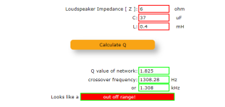
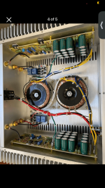
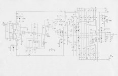
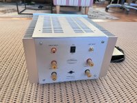
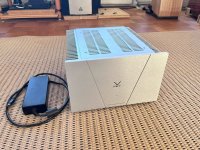
These are active DSP driven speakers. They need to be biamped (any high quality 4-channel amp, or pair of 2-channel amps of your choice). They are shipped with a MiniDSP 2x4HD Digital Signal Processor. It has inputs for analog, USB and fiber optic cables. DSP is "Photoshop for sound" and allows miracles that are impossible with old school passive crossovers.

When room reflections don’t match direct sound from the speaker, it sounds unnatural. Textbook speaker designs pretend the room is not there. But not only does the bass have room modes and standing waves, but the mid and high frequency reflections add LOTS of clues for your ears. Good clues make your ears happy.

PERFORMANCE SUMMARY
  • 30Hz to 25KHz with silky-smooth response in a real room that has real reflections. Not just in an anechoic chamber.
  • True Constant Directivity sound pattern 30Hz to 25KHz so imaging is superb anywhere in the room
  • Open Baffle Dipole sounds great even behind the speakers
  • High Efficiency – 95dB 1 watt/1 meter. Sounds great and plays loud even with “flea watt” single ended vacuum tube amps
  • High Power Handling and High Output – 100 watts & 115 dB running full range; 500 watts & 120 dB with subwoofer
  • Near-perfect impulse response
  • Near-perfect phase response
  • Low Distortion (<2% above 60Hz; <1% above 150Hz at 90dB)
  • Easy to drive: 8 ohms (4.5 ohms minimum)
  • Live Edge wood is so beautiful, non-audiophile wives of non-audiophile men gasped when I showed these on a screen in a Zoom meeting.
  • 3-way system is bi-amped (not tri-amped) using a MiniDSP 2x4HD.
It is not possible to buy anything like these at any hifi store. Open Baffle / Dipole designs are loved and celebrated for their room-filling sound and lack of boxiness, but are extremely rare. Live edge real wood is equally rare. They have a HUGE "Wife Appreciation Factor" - spouses love the natural wood. Competition Judge Jerry McNutt said, “The best way to not sound like a box is: Don’t use a box.”

The Live Edge Dipoles sidestep every pitfall of conventional designs. Giant notes roll out of the speakers. You enjoy a huge sound stage. You are immersed in 3D ambience, clarity and resolution. Dry recordings become spacious. Drums and toms hit with visceral, fist-on-sternum impact. These hold their own against the world's most prestigious designs - Wilson, KEF, Focal, Genelec, Estelon, YG Acoustics.

Constant Directivity means you have flat frequency response on axis, and as you turn the speaker in any direction, the level steadily drops off axis, but the octave to octave balance remains flat. Then imaging will be great anywhere in the room.

You can walk all over the room—even stand on the far side of the left or right speaker, and you still clearly hear the other speaker across the room and the imaging is still stable. There is no one “sweet spot.” Music sounds fantastic anywhere you go in the room. You can walk around and behind the speakers and they still sound great!

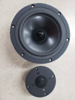
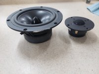
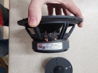
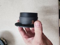
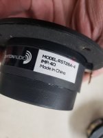
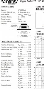
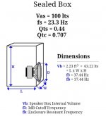
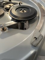
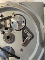
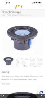
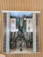
They are equipped with 18" Eminence Kappa LF woofers; 8" Radian 5208-C mids, with Beryllium diaphragm Coaxial compression driver firing through the center. A rear firing tweeter means the energy from the room matches direct sound. An L-Pad for the rear tweeter allows you to adjust balance.

The front-firing Beryllium tweeters are extremely transparent; bass is rich, expansive and authoritative; thorough top-to-bottom coherence and integration; warm, ambient and enveloping stereo image. They effortlessly fill a large room to overflowing with palpable output and dynamic range.

They sound best 3-5 feet (1-1.5 meters) from a rear wall.
birch__0080.JPG
birch__0053+.JPG
birch__0062+.JPGbirch__0061.JPGbirch dipoles 0 15 30 45 60 75 90 onethirdoct+.pngbirch_dipole_rear_above.JPGPOLAR birch dipoles 0 15 30 45 60 75 90 150-15K_10dB.jpgbirch dipole phase response 10 positions average.pngbirch dipole step response 13aug2023.pngbirch dipoles 1.5M frequency response 13aug2022 1-6octave.pngbirch dipole impulse response 14aug2023.png1st_place_award_live_edge_dipoles.jpegAX-Cover2021-01.jpg

On DIYAudio you will find extensive discussion of these speakers 
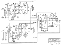
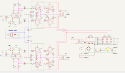
with full technical details. The photos here include in-room measured frequency response, impulse response, step response and polar heat map.

Shipping is by truck to the continental USA and will be arranged. Local pickup is encouraged, from my home in the Chicago suburbs. You can also come for a listen.

Custom In ear monitor driver asembly and sound design

Hi all. I know this was discused earlier, but the topic is soooo old...
So, i made my own in ear monitors with Knowles BA drivers GV-32830-000 and, obviously the next few days i spent with the big issue (for me):
HOW DO I MAKE THE SOUND BETTER? WHAT KIND OF DRIVER COMBINATION SHOULD I USE AND WHAT KIND OF CROSSOVER I SHOULD MAKE?
So, probably the main question in this thread would be...... : Are there any templates for buildin your own decent sound with impedance, resistors and induction metering?
Is it possible to find a guide or something so i could build a better sounding CIEM's?

Thanks in advance.
Sorry for my grammar and English mistakes, im not a native English speaker so to say.... 🙂

Thorens TD124 Idler wheel engagement… or lack there of…

Spent a good amount of time online but can seem to troubleshoot this. I should note that this is my first Thorens TD124 mkII so I’ve never experienced one in top working order.

When I got the turntable the idler wheel seemed to have issues with engagement. I’ve since gone through a detailed cleaning as per the many resources online and while everything is running and functioning great, the idler wheel does not engage the platter. It just sort of flops around.

I understand that with the platter off it will not fully engage.

Out of curiosity, I put an extra turn on the idler linkage spring to pre load it. This made the idler engage and the platter spin but this should not be the fix. I worry that this is putting stress on all components in the chair and will induce rumble. Also it seems like the clutch can’t stop the platter in this state.

I’ve cleaned and lightly polished and lubed all linkage parts and there is no build up of old lube.

Any help would be appreciated!

Attachments

  • IMG_9989.jpeg
    IMG_9989.jpeg
    326.6 KB · Views: 170
  • IMG_9988.jpeg
    IMG_9988.jpeg
    439.6 KB · Views: 142

PurePi + FifoPi Ma + Innomaker 5122 DAC: no output.

Hi all,
new here and pretty new to the DIY DAC world.
I have setup a Raspberry Pi 3b+ with PurePi, FifoPi and a Innomaker DAC 5122 on top.
I have powered the FifoPi from the PurePi 3.3 power supply with short cables.
All other connections are through GPIO.
All seem to be up and running, but I cannot get any sound out of the DAC.
I tried different Moode settings such as Allo Boss DAC in slave and non slave mode, or IANFifo II but nothing seem to work.
Any idea what I might be doing wrong?
If I remove the FIFOPi and put the dac directly on top of the raspberry, it works.
Thanks for your help,
Simone

IMG_3253.jpeg

KA Electronics Flat Moving Coil Preamp PC Board for RAW Transfers and Streaming Now $20 Off

The KA-Electronics Flat, Balanced Input/Output MC Preamp PC board, normally $39.95, is now $20 Off for a limited time.

Product information:
https://ka-electronics.com/shop/index.php?route=product/product&path=63&product_id=122
Construction information: https://proaudiodesignforum.com/forum/php/viewtopic.php?t=1179
ZTX851 transistors are available here: https://ka-electronics.com/shop/index.php?route=product/category&path=65

Flat_MC_Preamp_FMCP_28-1024x768.jpg


Use Coupon Code "DIYAUDIO20" at checkout. International shipping available.

Enter the coupon code at checkout here:
Cart_Coupon_Code.JPG
Projects by fanatics, for fanatics
Get answers and advice for everyone wanting to learn the art of audio.
Join the Community
507,624
Members
7,880,777
Messages

Filter

Forum Statistics

Threads
405,896
Messages
7,880,777
Members
507,624
Latest member
Neilonpoint