YouTube to Chromecast Audio, how to?

I can cast music from my mobile to the Chromecast Audio device using the Google Home app on Android (for connecting) and BubbleUPnP (for the actual streaming). However this doesn't work for Youtube. Strange thing is that I can send Youtube picture and sound to my TV as screen mirroring.
Digging in the net it seems others have the same incompatibility issue between Youtube and Chromecast Audio.
(Chromecast Audio is not the same as Chromecast. It has a 24-bit 96 kHz DAC and analog L/R outputs, while Chromecast has no DAC but has HDMI output).
Has anybody any working solution?

Hype aside: Is output stage bias VAS thermal drift compensation necessary?

Do we really need fancy bias schemes other than a simple voltage divider with two resistors and a bjt mounted on heatsink? Do we even need a capacitor across the voltage divider? The answer from my side for both questions is no, but it depends. Whats yours?

For reference here are three schemes
https://pcbwayfile.s3.us-west-2.amazonaws.com/web/24/04/06/2151267095210.png
https://pcbwayfile.s3.us-west-2.amazonaws.com/web/24/04/11/2340230765654.png
https://pcbwayfile.s3.us-west-2.amazonaws.com/web/24/04/10/0433204760624.png

Decware ZKIT-1 help needed

Hi guys

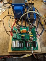
So a few years ago I picked up a pair of Decware ZKIT-1 2 channel amp kits that I got about 80% finished before sitting on a shelf for the next 3 years. I have some time off work and decided that I wanted to try and finish them.

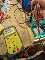
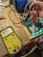
I have one amp fully assembled and wired in a state good enough to test. Unfortunately it does not turn on, the tubes do not light up. I've checked all my component values and all seems correct. The manual lists a few points to measure, points A and B both measure 430VDC, they're supposed to be 346V and 309V. The other points all measure zero. I have very little circuit troubleshooting knowledge and I'm sure I've missed something dumb, so I'm trying to learn.

I have attached the circuit diagram and my measurements. Any help is very appreciated.

Attachments

  • ZKIT1 (1).pdf
    ZKIT1 (1).pdf
    61.6 KB · Views: 209
  • Screenshot_20230930-171217.png
    Screenshot_20230930-171217.png
    108.4 KB · Views: 193
  • PXL_20230930_203859986.MP.jpg
    PXL_20230930_203859986.MP.jpg
    598 KB · Views: 192
  • PXL_20230930_205945041.jpg
    PXL_20230930_205945041.jpg
    541.7 KB · Views: 162
  • PXL_20230930_210015143.jpg
    PXL_20230930_210015143.jpg
    538.7 KB · Views: 177

Absolute beginners - Trying to figure out how to connect a woofer and tweeter

Hello there,

I have a set of speakers I intended to use in a DIY project - each has one 8 ohm 20 watt and the tweeter with 8 ohm 10 watt (or would that qualify more as a mid? I don't know 🙂. But, I haven't got the idea on how to connect them, and if if I need a crossover or a resistor between them. I've looked inside some older speaker and saw the tweeter/mid is connected to the woofer from the right and left, and on the right side there was a resistor. Any advice is welcome and please be patient with me 🙂

Thank you!

Tube maker ID 6550 who´s is-it

Hi All,
Through the years I know most power tube makes but picking a box up from flea market, who made this version of 6550 with a pellet getter. Is it Sovtek or another ? There is not an origin mark or clue on the glass, but certainally Russian origin. The ones I tried on the jig varied enormously. I hate tosay this, but they seem like redressed 6L6 variants, as anodes start glowing at 30W.

Any ideas ?

Bench Baron

Attachments

  • IMG_1759[1].JPG
    IMG_1759[1].JPG
    548 KB · Views: 82

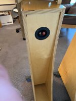
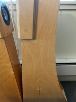
Need help for enclosure - Eminence Alpha 4-8 as surrounds and heights

Hi all!


So I just purchased a new denon 6700h. I will be upgrading from a 5.1 setup using a denon 1600h.


The denon 6700h as 11 channel. I plan on going with Auro3d speaker placement (or the placement that you can use for atmos, Auro3d and dts x)


I plan on using the Auro3d speaker placement. (Or the one that you can use atmos, Auro3d and dts-x)


Currently I have CSS Audio Criton as my left, center and right and paradigm ADP-190. I really love the adp-190 because as my couch is right on the back wall, the adp-190 diffuse more the sound behind us instead of screaming in our ears.


I’m the next couple of months, we will be moving.


I need to build 6 speaker. + 2 to be replacing the adp-190, as I’ve heard there not very good for surround when having the correct distance between you and the speaker, which I will have in my next set up.


So, I started talking to a friend of mine, and he ended up giving me 7 eminence alpha 4-8, and 2 in ceiling mica 8 inch. (I already have 4 other mica bought a couple years ago and ended up never using installing them.


My question are:


1- would I be better to build boxes for the mica and to use as my surround and heights? Can’t remember where, but I’ve read that it’s not a good thing and in ceiling speaker are not meant to have a box.


2- if building for emicence alpha 4, there’s 3 option I’m thinking.

2.1- building a regular, prism, sodden box.

2.2- going with the sonotube / 3D printed angled bracket.

(https://www.avsforum.com/threads/diy-cylindrical-angled-atmos-speaker-enclosures.3255712/)

(https://www.avsforum.com/threads/cr...rsl-c32e-in-ceiling-speakers.3293578/#replies)


2.3-

Speaking with my friend about the sonotube version, and that it’s not a good thing having a cylindrical (circle) baffle has it has lots of diffraction. So I suggested I could 3d print a half-sphere to go over and install the driver. Then he suggested that I print a bower will in shape:


IMG_1555.jpeg


So with the proved eminence drawing tonight I tried to model the 3d printed “bower wilking” enclosure.


Surrounds v3-1.jpeg
Surrounds v3-2.png
Surrounds v3-3.png


(Since those pictures, I rounded the corner inside the speaker, back wall and port)

Volume and port diameter and length is provided by eminence.
(https://cdn.shopify.com/s/files/1/0270/8665/1462/files/Alpha_4_8_cab.pdf)
See page 10


I want the build to be “quick” . I don’t want to spent all my free time making boxes for those speaker, but I want the best sound possible. Going 3D printed route would allow me to start the printer and do other things. When all pieces are done printing, I could glue them, install driver and binding post and call it a day. When I have more free time, I could sand them and paint them.


If going wooden box, I feel like I would need to spend “a lot” of time doing cuts and assembling, also, I could not finish the box, but I feel like they would be uglier unfinished mdf box and 3d prints.


What you guys think?

What about the bower will in shape?


Let’s talk!

I’ll add pictures after posting, the website on my cell phone doesn’t let me upload picture?

Amplifier build question

3-4 years ago I bought this 35 watt amp kit.

https://store.qkits.com/electronic-kits/audio-kits/35w-mono-power-amplifier-kit.html

The circuit shown is stock except the filter caps.

35 watt amp.png


I wasn't satisfied with it just barely doing 35 watts and the heatsinks getting real hot, so with the help of a solid state amp builders group on Facebook I modded it to produce 93 watts into 4 ohms.

I used one of the Legacy car audio amps that cram a maybe 30WPC or less amp into a thick rather large aluminum chassis with VU meters and a fan that due to the chassis design didn't blow air out of the chassis.

One amp channel installed.

20240503_201854.jpg


Part of heatsink cut so that the fan would actually blow air out of the chassis.

20240503_201932.jpg


Here's the modified amplifier.

The filter caps are 20,000uF not 40,000uF. I know there's some things that aren't exactly right.

The interesting thing about thick film resistors is when they get overloaded they simply go open circuit which is what happened to the amp when I was testing it at full output. Speaker leads briefly shorted and all four thick film 50 watt emitter resistors went open circuit.

35 watt amp 11.png


Question is do I keep this amp and build a second channel or do I go with this 100 watt kit amp?

https://store.qkits.com/electronic-kits/audio-kits/100-watt-mono-power-amplifier-kit.html

Schematic

http://www.funnykit.co.kr/bemarket/shin/menual/fk666.pdf

Two issues.

1. The amp requires +/- 50V versus the +/- 35V the current amp uses.
2. Only one pair of output transistors are used.

Attachments

  • 35 watt amp 11.png
    35 watt amp 11.png
    17.1 KB · Views: 99

Onkyo M504 power issues and blowing fuse

I purchased this Onkyo M504 a few years ago and recently it just powered off, no sound and nothing to the meters. When I opened the amp the top fuse on the board attached as pic 1 noted a blown fuse, I searched this site and found several posts regarding a faulty switch might be the cause of the blown fuse, I replaced the switch, attached the wiring and original snubbers to the new switch, placed a new fuse in. When engaging the new switch, the VU meter lights came on, but within a few seconds the same fuse blew again. I am far from technician level, and it has been a long time since I built a couple of Heathkit amps, so my experience is old and limited for sure, but this amp seems pretty straight forward and I am in hopes it is something I might can repair.
From looking at the wiring, it appears the board that the fuses sit on has connections from the power switch, grey and brown wires which connect to posts at each fuse location, the AC power cable has conections to both sides and the accessory AC outlook on the rear of the amp does the same. Then from that circuit board yellow and white wires go from each fuse side to the two transformers.
I would presume with the wiring and the fuse location that the issue is prior to the transformer stage and if not the switch causing the fault, is it the AC power cord, or something else?
The solder joints look to be OK, and none are loose. There is no apparent or noticeable damage to the circuit board. Any help is greatly appreciated, I do love this amp, I have other options to run, but I do want this one back to working order. Thanks in advance

Attachments

  • M504 pic2.jpg
    M504 pic2.jpg
    427.3 KB · Views: 70
  • M504 pic1.jpg
    M504 pic1.jpg
    505.3 KB · Views: 65

Dean Markley DMC-80 50Hz Hum

Hi!
I have this DMC-80 on the bench with a hum problem. I usually only do hifi gear but as I know the person I wanted to give it a try. The filter caps were in pretty bad shape so I replaced them but as the hum is 50Hz this didn't fix it. When I plug something in the line in the hum disappears so I'm thinking it's in the drive/tone stage. Turning up the volume does increase the hum somewhat. I did check for cold solder joints but didn't find any, removing safety ground (just for testing) doesn't improve things either.

Attachments

MySqueezebox.com shutting down

Logitech has just announced that they are shutting down MySqueezebox.com next month. Their players can still work with a local music library but they won't be able to access streaming services.

I'm curious if someone in the community will come up with a workaround for the different services.

As much of a bummer for users of their streamers, it is impressive that they kept it running for over 11 years after they stopped making the streamers.

Happy Cinco de Mayo

To all my Mexican friends, on this day of celebration. May 5, 1862, the day the Mexicans repelled the French in the city of Puebla. It was the last time a nation from off the continent invaded the Americas.

We will be celebrating with traditional dishes and garb, (no, not tacos) music and dance and remembering how lucky we are no matter our current conditions. I hope you do the same.

Buenos dias, buenos noches.
  • Like
Reactions: phase

For Sale New Custom Preamp Boards

Hello,

I have 3 brand new, spare preamp boards left over from a recent project. You can find out more about the board in my thread here as it profiles my new build. The detailed features and more pictures are included in the thread. Here are pictures of the new double-sided board.

Resized Top_PCB Silkscreen7.jpg
Resized_Bottom_PCB Silkscreen7.jpg


The pre boards are professionally made and are fully populated with SMDs from the factory (JCLPCB), except for 9 devices that were not available for fabrication. These 9 devices (SMDs) will be supplied (unsoldered) with the board. In addition to the populated boards, there are several through hole parts that will be needed to complete a functioning preamp. That parts list will be supplied with the board, and as of today, are priced in total, at around $75USD at Mouser.

I'm asking $125 for each board including the 9 SMD devices, plus postage ($12) to anywhere in the continental US.

PM me more details if interested, or have any questions.

Thanks for looking,

Rick

Philips CD101 repair

Hi everyone,
I am the original owner of a Philips CD101, which I have owned for approx. 37 years. All these years the player worked great and I love its sound.
Recently the player refused to turn on. Reading about similar issues on this and other forums, I understood this is a common issue due to old capacitors drying out.
I have reasonable experience repairing electronics, so I thought I could do this myself. I bought this recapping kit: Philips CD 100+101 Player Power Supply Electrolytic Capacitors Vishay Power Supply recap recapping Kit | eBay, unsoldered each capacitor separately and replaced with the corresponding capacitor from the kit, while observing the polarity.
When I plugged the player back in, the LED's flickered on and off and the player made some strange sounds. When I carefully checked the board with a magnifying glass, I found several "cold joints", especially around the power supply transistors, so I resoldered those joints.
When I plugged the player back in, the LED's came on and stayed on. I inserted a CD and pressed "Play" but the CD did not turn. I tried several times, until I saw smoke coming out through the top of the player, in the back, approx. mid-way. I immediately turned the player off, unplugged, opened it up again, and found that capacitor no. 2291 (100 uF) had popped.
After unsoldering, I checked its polarity and found it was incorrect. I must have made a mistake when replacing this capacitor.
Not having another new one on hand, I replaced it with the old one (I do not have a way to check whether its value has deteriorated but the old capacitor does still seem functional). I tried the player, and now it comes on properly, but the CD still doesn't turn. I permanently shorted the contacts of the CD door to check that this wasn't the issue, and indeed, even with the door contacts shorted the CD doesn't turn. I was able to observe the laser assembly moving back and forth and up and down, attempting to focus. And when I power off the player, the CD turns a little bit, as it used to, so the motor is apparently working.
What could be the issue? Any help would be very much appreciated.

DLM4000A no switching impulse.

Hello guys, i have an amplifier D class Impact that have as a driver board DLM4000a, i have checked everything on this board but without results, no swithicng impulses, I have already desoldered IRS2113 but it's not a problem i have no input signal to this IC. Audio input arrive to pin 9 of DLI4060b and after i don't understand what formed signal to HEF4001BT? Anybody could help to me? Thank you in advance

Looking for non-DRD 300B using D3a as driver

Hello,
I was wondering if anybody knew of a great 300B design that uses the D3a as the driver. I have searched this forum and eleswhere but I continue to only come up with a DRD topology.

I recently sourced all the parts to build the JEL 300B and bought an extra set of OPTs from James (6123HS). I was toying with the idea of using this D3a in a 2A3 project I am completing but went a different direction with that one. In the process I picked up 4 of the Siemens D3a drivers and now I am thinking I might try them in a 2 stage D3a/300B amp since I have the parts (some of them at least).

Any suggestions for some designs? I wanted to stay away from the DRD designs b/c my power transformer selection I have won't get me the voltages I see with most of these designs.

Thanks,
Jeff

Klipsch RF15 - The temptation?

Triggered by the frequent criticism from gr-research of the simple two-way loudspeakers, especially the standard hi-fi floorstanding speakers from Klipsch, I took a pair of old RF15s from the cellar and put them on the measuring table.

That was some time ago now.

After a lot of back and forth, I decided to follow Danny's general recommendations. I designed several concepts of potential crossovers/filters. From the two-way system to the three-way to the two-and-a-half system, everything was included.

Everything was recorded using measurement technology; I use CLIO and both a Dayton and a well-known Bayerdynamic measurement microphone. The entire program was used as methods: ground plane, tripod, various excitations, distances, just the normal madness -> measurements in a low-reflection room/chamber (RAR) would also have been possible.


The HT with its horn differed a lot from the two speakers, let's get this out of the way right away. This difference in SPL was clearly audible later with the new crossovers.

(...)
  • Like
Reactions: GM

KEF Blade Uni-Q drivers

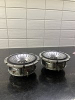
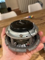
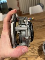
Selling 3 pcs Uni-Q drivers from the original Kef Blade.

This is a very rare find for anyone interested in making their own DIY speaker of probably the best engineered coax driver on the planet (except blade/ref meta uni-q)

Used roughly 3 years in a dedicated listening room. (active system, with security capacitor on the tweeters)
Rest of the time it was stored dry and safe.

Two of them are 10 years old, and 1 of them is 6 years old.

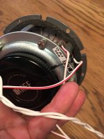
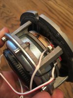
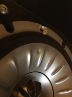
One of them has a slight dent as can seen in pictures, which i did not notice whether in measurements or listening.
Besides that they are in good working condition.

Asking 1500 USD / 1400 EUR + shipping for all three drivers.

If anyone needs only 2, they will need to buy all three
kef_blade_uniq_605.jpg


.

Attachments

  • IMG_8651.jpg
    IMG_8651.jpg
    345.9 KB · Views: 115
  • IMG_8791.JPG
    IMG_8791.JPG
    374.3 KB · Views: 117
  • IMG_8790.JPG
    IMG_8790.JPG
    408.9 KB · Views: 100
  • IMG_8648.jpg
    IMG_8648.jpg
    370.9 KB · Views: 107
  • IMG_8647.jpg
    IMG_8647.jpg
    391.5 KB · Views: 112
  • IMG_8321.JPG
    IMG_8321.JPG
    25.8 KB · Views: 109
  • Like
Reactions: taloyd

Building Elvee's Circlophone: Documentation, Parts, Accessories, & beginner friendly

Building Elvee's Circlophone: Documentation, Parts, Accessories, & beginner friendly

Intro
Circlophone is a new topology (a more efficient Class A, dynamic class AA), with a live sound character and an easy build. These are fun!

The Original, optimized Circlophone
The Germanium Circlophone
Inverted Jfet Circlophone

Sample schematic:
454782d1419069488-building-elvees-circlophone-documentation-accessories-beginner-friendly-circlo-headline-gif


Parts options
♦ Q9, Q11 Driver: KSA1220, 2SA1930, 2SA1837, 2SA968, 2SB649, Philips/Harris BD140, and ST's BD140.
♦ Q5, Q6 VAS (cob 4pF~16pF): 2SC5171, 2N3019, 2SC3421, 2N1893, MosFet; Or if < 5pf like 2SC2911, BF819, add this cap.
♦ Q12, Q13 Sensor: BC546B on 25+25vdc rails,:att'n: With higher voltage use KSC1845, 2SC1845, 2SC2240, 2SC2705 or 2N5551.
♦ Q4, Q3 Input: A Philips/NXP BC556B (post 7) is on the original, or nicely HFE matched BC556C or BC560C with a multimeter.
♦ Q8, Q10 Output: MJE3055, BD249C, MJ802, MJL21194, MJW21196, MJ21194, MJ15022, MJ15024, MJ15003 or the classics.
♦ D4, D5: Low voltage drop and high current handling is important, like 5a, 7a (MBR735), 10a (MBR1035) Shottky diodes.
♦ D8, D9: see convenient sizing chart.
♦ D7: BAT type "Signal Schottky" like a BAT86, BAS86, BAT85 or BAT54, available at Mouser & RS. Or there is an alternative.
♦ R21: "The value in KΩ ~ = 0.9 times the total AC supply" Or review Elvee's selection guide. Or, see convenient sizing chart.
Build specific:
♦ VAS on Piersma's Circlophone CFP build can be Sanyo 2SC2911 or 2SC3955, or similar specs.
♦ Terrangima's Darlington & MOSFET Circlophone has its own devices listed on the schematic--See post#226.

Notes
♦ Discussion of topology and modifications: Circlophone discussion thread
♦ Various brands of 2N5551, 2N5401: Quality Control--check the HFE
♦ Various brands of 2SB649, Quality Control: Click Here
♦ If using faster output devices, click here and install C11.
♦ Other parts selection questions? Here is a link to Elvee's build notes.
♦ Checking R21, Elvee said: "Measure the voltage, divide by the resistor value, if it's 1.5mA +/-50%, it's OK"
♦ While you're measuring, it is also easy to check the idle current.
♦ Elvee's LTSpice Circlophone simulation file for the original Circophone.
♦ For an example parts list, aka BOM (Bill of Materials): Click here.

Accessories
♦ A Jfet buffer isn't mandatory but if you want one for constant input impedance, click here.
♦ To solve offset bounce versus power issues, Elvee has published an optional offset trimmer circuit.
♦ Circlophone has Class A sound but if your sound is too mellow there's compensation in the LTP soft clipper.
♦ If you have efficient speakers in combination with big gain for big dynamics, you might want a limiter to stop x-max.
♦ Circlophone has very simple power supply requirements so regulated is unnecessary, but if you wanted regulated click here.
♦ To block thumps from single rail sources (computer) power up, and block some RF too since it is slightly capacitive, look at this.
♦ Circlophones go in the house, at work AND: Boostor, a companion for a Circlophone on the move, rock the the car, RV and boat too!
Technics RSM14 cassette deck HELP!!

Hello. I have a problem with this machine, while I think about writing the query I think that maybe I have the answer in front of me, but I don't know. I changed all the belts (4 in total) and pinch roller, I adjusted the speed with a cassette with a recorded 3KHZ signal and after about 10 minutes the speed began to decrease until it reached about 150Hz less (2850Hz), I replaced several motors, all with internal speed regulation (I clarify that they are not new motors) and the symptom is exactly the same without differences between them, the supply voltage is fine in absolute value and ripple (unregulated voltage), all the parts that rotate do so with Total smoothness, the consumption of the motor without cassette is about 90mA (the motor always rotates when turning on the machine) and rises to about 130mA by dragging the tape. As an additional detail, if I adjust the speed as soon as I turn on the machine, and leave it with the motor running for a while but without the cassette, the result is the same, that is, the speed decreases. I also tried cooling parts with freezing spray without success. Everything seems to indicate that the motor is the problem, but do all the ones I tried do the same thing? Am I missing something? Thank you so much.

Seeking Advice on building a stepped potentiometer

Hi

I just got hold of a 15 steps Plessey make before break rotary switch and intend to use it as a stepped potentiometer for volume control of my passive pre-amp.

I am seeking advice on the resistor value required.

Using the HiFi Collective 50K Shunt 46 steps as a guide, I decided to skip every 2 steps on their 46 steps, and used the remaining for mine. Is this the correct way?

(Number rounded)

1 - 0R
2 - 18R
3 - 50R
4 - 100R
5 - 200R
6 - 400R
7 - 800R
8 - 1K5
9 - 3K
10 - 7K
11 - 11K
12 - 17K
13 - 27K
14 - 50K
15 - 121K

Thanks!
IMG_9500.png
  • Like
Reactions: Michael C

Drill bit chatters

Hello Forum Members,
Looking for advice for future reference. I recently drilled a 3/4 inch (19mm) hole through a 10mm modushop aluminum front panel. Unfortunately the bit chattered terribly giving me an adequate but not perfect hole. (Rough edges).
I am assuming my main mistake was not having my work clamped down tightly. The trailing edge of my panel rested against the pedestal of the drill press so the work couldn't catch and spin, but the bit did chatter.
I used a decent drill press, decent (and expensive) cobalt bit, and aluminum cutting fluid. I had previously drilled a 3/8 inch pilot hole.
Next time I will clamp my work. Any other pointers? Thank you for helping out a construction novice.

For Sale Frugel-Horn Mk3

For local delivery only. Seattle
Frugal horn Mk 3 built from Flat pack. Includes FE126eN and also mark audio drivers (can't remember what model). Also includes the outrigger and removable baffle for driver swaps. Seldom used and time to pass on to someone.
$200.

Attachments

  • IMG_2617.jpg
    IMG_2617.jpg
    678.8 KB · Views: 143
  • IMG_2619.jpg
    IMG_2619.jpg
    561.6 KB · Views: 140
  • IMG_2621.jpg
    IMG_2621.jpg
    57.1 KB · Views: 131
  • IMG_2623.jpg
    IMG_2623.jpg
    443.1 KB · Views: 140
  • Like
Reactions: itsikhefez

TDA1521 - possibility of reduced gain?

I've been looking at ways to get output powers above 20W or so (the output of my TDA8932 implementation) for quite some time now and last week was getting quite close with my idea of stacking TDA1566 amps (putting them in series with isolated PSUs). The TDA1566 has the great feature of being able to drive down to 1R loads in mono mode which means it has a very generous output current capability. But several of my prototype builds of TDA1566 failed unexpectedly (before I even got to stack them) so I've become suspicious of the quality of chips I have been getting. The TDA1566s from Taobao are new, not recycled so I'm veering towards the conclusion of them being sub-par devices.

The other very nice feature of TDA1566 is it has a low-gain mode (16dB) with impressively low output noise (~22uV). No other chipamp I've seen delivers such low output noise, mostly because they don't have the capability to run such a low gain. Enter TDA1521, its unique in NXP's chipamp line-up in that there is the apparent capability to run it at a lower gain than stock (30dB) but how low it can go before it goes unstable is anyone's guess. Hence this project in which I hope to uncover how low it can be pushed. The ability to trim the gain channel by channel opens up the possibility of running these devices in parallel - to minimize cross-conduction the gains of the parallel elements do need to be very closely matched, much better than the DS gain variability (0.2dB typical).

internal-structure1521.png


Here's the internal structure of the 1521, only one channel shown. The unusual feature here is that 'INV1' pin is brought out of the package rather than being returned directly to AC GND on-chip. Which means some extra series resistance can be added which will have the effect of lowering the gain. The resistors on-chip are not close tolerance so the 680R and 20k could be anywhere within 30% or so of their nominal value which means the external R needed for a particular gain will have quite a wide range of possible values. Therefore I'm going to use a multiturn trimpot to realize that. My initial target is to get down to 20dB gain and see if that's still sufficiently stable....

Rockford Power T1000-4AD

This unit has one damaged channel. U1 is a IRS20124S. Is there something else I can use without needing to replace them in every channel? Also, D32 has JS written on it. Not sure what that part is. Q21 says 2Q and Q22 says W1A? I have to go out but will try to look up the 3 in the code book later or tomorrow. Biggest issue currently is the IRS20124S. I got the output transistors.

Thanks in advance!

Pics coming in a minute 🙂

Attachments

  • 20240417_203649.jpg
    20240417_203649.jpg
    692 KB · Views: 94
  • 20240417_201729.jpg
    20240417_201729.jpg
    433.3 KB · Views: 83
  • 20240417_201706.jpg
    20240417_201706.jpg
    268.4 KB · Views: 87
  • 20240417_201558.jpg
    20240417_201558.jpg
    537.7 KB · Views: 95
  • 20240417_201742.jpg
    20240417_201742.jpg
    364.9 KB · Views: 91

Design for a sealed cabinet for a mid-range

I'm designing a 3-way box, and for the 4" speaker (which will be the mid-range speaker in the box) I will use a full range with crossover, and I would like this specific speaker to be in a sealed box, so how can I design a sealed box for a mid-range speaker?
I will use a GHXamp speaker from Aliexpress for this project
I was thinking about using WinISD to do it, but I have my doubts...

I was thinking about using WinISD to do it, but I have my doubts...

For Sale DDDAC power supply

This power supply features DDDAC boards, twin transformers, 4 x Llundahl chokes amongst other things, all in its own chassis with umbilical connection to supply a separate DAC. This PS is designed to power a dual stack ie one multi-DAC board stack per channel.
Ideally I would like to sell this PS as it is. if you are interested in buying it then let me know and we can discuss the price.

If no-one is interested in buying it as it stands then I shall take it apart and sell the parts:
IMG_1135.jpeg

YBA DT INTEGRE - problem bias

Hi. Sorry for my english.
I have Yba Integre. When i rotate trimmer potentiomer for left channel to set bias, values for other channel also change? If i set 2-3mv for left channel, other channel automatic is 130mv. If i set 40mv for left channel, other channel is 105mv. When i set two trimmer potentiomet to min , on both channel i have 60mv.
Can you tell me how the transistors are located (TIP35/TIPC)
With RED dots, which are transistors? Tip 35 or tip 36?

4-way i2s switches

Hi all,

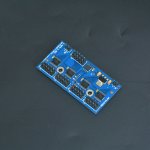
I searched and couldn't find a thread on these boards, now common on Aliexpress and eBay and I'm sure plenty of others. Audiophonics has a slightly different version (I think it is a previous revision of the same board but with a different pin out).

Anyway, the principle of operation is that it runs off 5V, uses a microcontroller to switch from one input to another. The lines are switched through 4x 74HC573 D type latches, and each of these is turned on or off via a (momentary, NO) repeated button press via an STC15W101 controller. Upto 8 lines can be switched per input (10 pins) with 2 ground pins. There are different levels on information out there available on these - the Aliexpress info tends to be short, but some ads on eBay contain a bit more info.

I've managed to let the magic smoke out of two of these now, so I can say they aren't super robust, but outside of that do certainly work. On the first one that I killed, I had grounded some of D1-D8, and you'll see in the quoted text below that this is not recommended. In the second case, I believe that I hit a short and some current flowed through the ground. The end effect is that one input stops working in such cases - in essence it becomes a 3 input switch. What I don't know at this point is whether the microcontroller has been killed, or one of the latches. - I will try to figure that out when I get some new parts here.

The text from eBay is quoted here, and you'll see there is reference to the two pinouts.

I've posted this here for comments and any obs anyone might have. I think if there is a way to make this unit more robust, it might be worth it.

Four-way audio I2S / IIS switching module! Choose one out of four! I2S buffering! I2S 4 choose 1 module!
The default price is for loose parts
!!
The function of this module is up to four I2S signal inputs. Select one of them to be transmitted to the following DAC decoder and other equipment! (You can only select one of the four channels for use, you cannot combine four channels into one channel). . .


This module is controlled by a single-chip microcomputer (a single-chip microcomputer has been integrated on the board and the program has been written, and the buyer does not need to use the single-chip microcomputer to control it). The buyer only needs to use an external button to choose which signal to use (note that the external button is a key (unlocked) It is not a switch), and has a power-off memory function (the signal selected last time is automatically used when the next power-on). When using one signal, completely block the other three signals to avoid interference. Each signal can transmit a maximum of 8 signal lines, in addition to 4 used to transmit I2S signals, the remaining four can be used to transmit other signals such as DSDON signal mute signal, etc. (of course, the remaining four lines can also be used to transmit another group of I2S For four-channel use, how to use it can be freely played).
Detailed introduction:
The IN-A IN-B IN-C IN-D connector on the board is four-way signal input. The OUT interface is an output. The But interface is used to switch signals using external keys. The POWER (or + G) interface supplies 5V DC to the power interface.
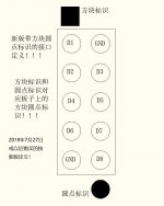
The interface definition of the new version was updated on July 27, 2019. For users who purchased before, please check the definition of the old version!
The definition of the input and output interface is as follows (note that the new version and the old version are distinguished, the new version of the board has a square and dot identifier, the old version is marked with the number 1 next to the interface): the input and output interface definitions are the same but the signal direction is different -C IN-D direction is input, OUT direction is output!

It should be noted that when one of the signal lines such as D1 is used as a DATA data line, then D1 of all input and output interfaces must be used as DATA; D2-D8 is the same reason.
Note: The GND of each board can only be connected to GND. D1-D8 cannot be used as GND! D1-D8 can only be connected to signals and cannot be connected to the front and rear boards instead of GND! !! !! When connecting to the GND of the front and rear boards, you can only use the GND pin! !! !! !! !!
Connect + of the power interface to 5V G to GND. The wrong connection will damage the board!

When the But interface is connected to the button, the two wires of the button must be connected to the But interface. Please do not lead from other places. The two wires connected to the button cannot be connected anywhere else, otherwise you will be responsible for any problems!
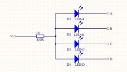
A B C D V 5 single-character interfaces on the board are used for LED display (new V character is changed to 3.3V)!

Attachments

  • board pic.jpg
    board pic.jpg
    458.8 KB · Views: 316
  • leds.jpg
    leds.jpg
    26.6 KB · Views: 264
  • pinout.jpeg
    pinout.jpeg
    64 KB · Views: 257

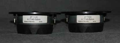
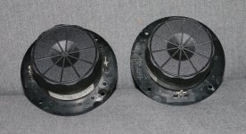
For Sale Pair of NOS SEAS 27TDC H1149 Sonotex soft-dome tweeters

Selling a pair of immaculate Seas 27TDC H1149 Sonotex soft-dome tweeters - NOS / "new old stock".

Bought new back in 2006 (made in Norway, week 34, 2005), but never got around to using them in the project they were intended for.

Would prefer to ship within EU (25eu); open to shipping elsewhere as well, pending checking costs - customs and any other fees are the buyer's responsibility.

Looking to get ~120eu, but i'm open to offers 👍

Price reference: https://www.soundimports.eu/en/seas-27tdc.html

Payment via Paypal, Mobilepay or bank transfer.

Attachments

  • IMG_1534.JPG
    IMG_1534.JPG
    393.2 KB · Views: 60
  • IMG_1536.JPG
    IMG_1536.JPG
    127.2 KB · Views: 55
  • IMG_1538.JPG
    IMG_1538.JPG
    479 KB · Views: 58

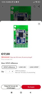
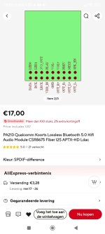
How to solder this Ldac module to an amplifier?

Hi everyone, i have made some bluetooth speakers with a aptx-hd module from AliExpress. It works, so i'm happy with it. I have a spotify Membership and they maybe gonna release a lossless audio option this year. So i have searched in AliExpress for a lossless bluetooth module and came across this one.. it has bluetooth aptx-hd and Ldac ( which is 900 kbps ). The problem is i dont know much about those chips and there doesn't seem to be an aux output. Does someone know if i can solder this module to an amplifier input and how?

Thanks!

Attachments

  • Screenshot_2024-05-06-13-52-45-673_com.alibaba.aliexpresshd.jpg
    Screenshot_2024-05-06-13-52-45-673_com.alibaba.aliexpresshd.jpg
    181.5 KB · Views: 70
  • Screenshot_2024-05-06-13-53-05-595_com.alibaba.aliexpresshd.jpg
    Screenshot_2024-05-06-13-53-05-595_com.alibaba.aliexpresshd.jpg
    172.9 KB · Views: 73
  • Screenshot_2024-05-06-13-53-52-220_com.alibaba.aliexpresshd.jpg
    Screenshot_2024-05-06-13-53-52-220_com.alibaba.aliexpresshd.jpg
    142.1 KB · Views: 68

Problem Audioqueest AQ190 Mk2

Good evening guys, I have a question, I own this Italian amplifier, audioqueest aq190mk2 ( the series before the qmoss steg series) , this amplifier does not go in mono, there is no selector switch, and neither does the output silkscreen with the mono inscription.
Like the orion series it was sold with a phase shifter, one input was shifted 180 degrees, and so you could bridge it.
I saw a couple of “universal” circuits on the net as btl , using tl072 op-amps, has anyone made a homemade phase shifter for old school amps, which needed this?

thank you very much

Dynaudio Contour 1.3 SE broken

A person dropped one speaker. The resulting damage was a tweeter with offset magnets (tried to realign) and a crackling woofer.
The original speakers are as follows:

Tweeter: D28/2 titanium with double magnet (No.81473)
Woofer: 17cm 17W75-LQ Titan (No.84871)

Can you tell me if there are equivalents on the market that can worthily replace the original components?

Using an audio amplifier to heat filaments (high freq. AC)?

A while back I remember Pete Millett was experimenting with heating tube filaments at an AC frequency well above human hearing. I thought that was a very interesting approach. I was thinking, (dangerous newby), couldn't I do that with a cheap $12 class D amp board and a $5 Chinese sine wave oscillator board. I have some small ($12 each) class D boards that actually put out 60 and 120 watts to a speaker, isn't that enough to also heat a vacuum tube? Can I just play the oscillator at lets say 80kHz into the input, then hook the tube to the speaker terminals, then set the voltage using the volume control? To make a high frequency AC heater supply.
  • Like
Reactions: Bigun

Plasma speaker project

Hello everybody,

I've a company creation project, to produce an high end plasma speaker, not talking of those" arcs" or "sparks" toys on youtube...
but something with good distortion and sound levels specs.
I own plasma speakers, and I have work for years on cold and hot plasmas.

I'm interested in what you would really like...
Any requirements, features, design ideas are welcome (Wich sound input you would like etc...)

Technicals specifications :
(a full range is a dream but not achievable due to excessive power consumption)
Low cutoff frequency :

Price :
Wich price would you accept to buy a pair ?

Thanks for your comments.

Pa

Add an AES output to a China Amanero based DAC

Hi,

I wonder if it would be possible to add an AES output port on a china dac that is based on amanero, I have replaced the china amanero with a original one latest version, and I wonder if it might be possible internally add a aes adapter by piggyback the i2s signals from the amanero card mounted inside the dac.. just feed the aes adapter with 5v/3.3v and the 4 i2s data lines. That the amanero will share the signals to both the dac board it's mounted to and then take same signals and send to the separate amanero aes adapter board. Anyone know if this would work? Or anyone have a solution to my idea?
  • Like
Reactions: yulen

Native DSD output on multichannel I2S (e.g. RPi5) possible?

When comparing native DSD and I2S formats, they seem to be quite compatible. IMO two I2S/PCM data lines could be used for creating a native DSD interface. The 32 bits of each DSD channel could be split to two 16bit PCM channels, using 4 PCM channels (= 2 I2S interface data lines) for each DSD channel pair. RPi5 could output 4ch DSD256 (8ch I2S at 176.4kHz running with 32bit frames bclk = 32fs). RK 3308 (e.g. Rock Pi S stamp module) could output 8ch DSD512 (RK3308 I2S runs ok at 16ch 384kHz). Only the bit clock and data lines would be used, the frame clock (LRCLK) would be ignored.

IMO it would "only" take an alsa-lib plugin which would accept existing alsa DSD formats and shuffled the bytes for a multichannel PCM-format alsa I2S device. Any native-DSD-capable player (e.g. mpd-dsd) could use it on any multichannel-I2S SBC.

A boom in multichannel hats for RPi5 can be expected, those having a DAC chip with DSD support could even offer native DSD 🙂

Creating a complete library management system for my use case - help needed

I have recently built my own Unraid server, where I am storing my music library (currently as a mirror of the local files on my MacBook Pro). This Unraid backup is itself backed up to BackBlaze B2, and I also am using ZFS. My plan is to:

  • Make my Unraid server the source location of my music library, and delete the current music library off of my MacBook, freeing up local space while still being able to access my library as a mounted volume with SMB and play back using Swinsian on my Mac, or via something like Plex on other devices.
    • This means I need a good method of having my current music player (Swinsian) point to the Unraid server as the new location of the music library, while retaining all the current playlists I have set up in Swinsian. My concern is that by changing the location, and therefore having copies of tracks become the new default location, Swinsian won't regard them as the same tracks as the ones it currently has (my local files) in all my playlists. How to ensure the changeover doesn't affect this?
    • Similarly, I DJ and use Rekordbox. I am going to follow this promising guide and tool from u/MixMasterG in order to locate my Rekordbox tracks following the change in location from local storage to Unraid server. If anyone has any experience running their Rekordbox based on a remote, mounted shared folder, I'd be keen to hear any tips or general advice.
  • Have a good workflow for the following actions:
    • How I download and sort music:
      • Music from private tracker torrent sites I'm a member of, or Soulseek > some light file name and metadata modifying > sorting these newly downloaded files into folders in my music library (stored on the Unraid server), maybe having some kind of automatic folder sort for "newly downloaded" or "not listened to yet", or something similar if anyone else has any good systems worth sharing.
      • I've heard of a way of setting up automatic downloads of torrent files from trackers that meet certain filtered criteria? No experience with that kind of stuff, would be keen to learn.
If there are any other actions, tools, programs, workflows etc that people have experience of and suggest I look at, that would be cool too. I'm new to the server game and looking to create a complete workflow/music management system.


EDIT:

For clarity r.e. what I want to do with my Swinsian music library:

1. I currently have Swinsian set up to watch a local music folder on my MacBook, which contains my music library.
2. I want to migrate to the mirrored copy of this library, stored on my Unraid server, so that I can delete the local files and free up space on my laptop.
3. If I go and tell Swinsian to stop watching the local folder, and start watching the mounted server folder, and remove the local files from my Swinsian library, surely that's going to result in, well, my current Swinsian library being destroyed, with all the tracks I have set up in all the playlists I've gone disappearing, even though all the files still 100% exist, just remotely in a different location.

So what I want to do is ensure a seamless transition to the server, maintaining the library as I have it now, just switching to having the files stored off the laptop.

no mercy simulator killer circuit

Thread title borrowed from Nelson Pass.

https://www.diyaudio.com/community/...rtion-killer-circuit.24192/page-5#post-296714

I know that simulations are neither accurate, nor reliable, nor credible, nor are the results achievable in reality, nor [add here what you like]

My simulation results in Microcap12 before 1 month looked like this:

Conditions: Bias 1.5A. Load 8 ohms. Peak power. THD @1kHz

1k: -208dB should translate into 0,000000008 %

I started to become suspicious because THD was already flat until 30W or so...

In the past, when the circuit was not so refined, distortion was always constantly rising with power, starting at -180dB at 10mW power.


thd_1k.jpg

Transistor arrays

Hi, I was thinking about transistors arrays for LTP and current mirrors, etc. ULN2003
They are darlington and most likely not what it should be for that use.
But I found these :
https://eu.mouser.com/new/that-corp...T*MTcxNDgzMTczMi4zLjEuMTcxNDgzMTc5Ni41OS4wLjA.

https://pdf1.alldatasheet.com/datasheet-pdf/view/561341/ETC2/300S14-U.html

Anyone used something similar before?.
- Bruno.

[Build Log] Streamer, modular electronic crossover amplifier

After asking for some feedback on my platform to easily prototype any of my future DIY audio project on Reddit, I started designing/building it and thought I could have a build log in case anyone is interested critiquing/reproduce any of it.

Streamer/Receiver:
  • Software/Configuration
    • [✔] APT-x Bluetooth
    • [✔] 96KHz Pipewire Config
    • [✔] I2S Slave config to Main DSP
    • [✔] I2C Bus communication to Main DSP
    • [✔] SPI Connection to OLED screen
  • Schematics/PCB Design
    • [95%] Parts selection
    • [✔] I2S Over HDMI Driver
    • [75%] Motherboard
    • [25%] S/PDIF receiver: Still trying to decide between 3 ICs (CS8421, WM8804, DIX9211)
  • Soldering/wiring
  • Mechanical/CAD
    • [✔] Modeling Rotary Encoder
    • [✔] Modeling OLED Screen

Plate Amp/Digital crossover:
  • Software/Configuration
  • Schematics/PCB Design
    • [✔] Parts Selection
  • Soldering/wiring
  • Mechanical/CAD

line pre-amp w smartknob

Hi!

I recently got hold of a power amp almost by mistake and now need a pre-amp. I haven't found anything on the market with the desired functionality and an acceptable price, so i am thinking about building it myself. I have no experience with building amps but I have worked with arduinos and raspis.

The first stage of the build would be the line stage for which I have looked at these components:

If I get this to work, then I'd like to install an IR remote, a phono stage and a BT dac to the relay switch. Also, I have two speaker zones (also on the power amp) and need to add a switch to the output for A, B, A+B output later on. It's going to be unbalanced.

I know I'm naive, but as far as I can tell, the components are basically readymade and it's a matter of soldering them on a board and connecting them up. I must be missing something, right? Please tell me this won't be as easy as just wiring the parts together.

Suggestions and critisim is much appriciated
  • Like
Reactions: wirewiggler

Theoretically best subwoofer enclosure

Hello everyone 🙂

I've been thinking about building a new subwoofer for my (bedroom) studio.
Being able to 3D print things I was wondering what the theoretically optimal subwoofer design would be.

I guess a flush mounted and sealed design dsp corrected up in to sub to be flat. (At least that my guess)
But even then, having a cube inside as a shape wouldn't be perfect right? Or doesn't it make a difference because the wavelengths are longer than the enclosure?

Apart from this, I can't flush mount. So what would be the best subwoofer possible? A sealed sphere? Or would a simple bass reflex / transmission line be better because it's (probably) flatter up to the rolloff point?

Is it even necessary to think about that?

LG
Johannes
  • Like
Reactions: camplo

Plate amplifier question

I've got a Dayton Audio SA100 subwoofer plate amplifier.

https://www.daytonaudio.com/product/778/sa100-100w-subwoofer-plate-amplifier

Two questions.

1, Is there a way to increase the sensitivity of the turn on circuit? I use it at work and use bookshelf speakers on my desk meaning the sub is real close to me and for normal listening levels, the sub often won't kick on.

2. The amp best as I can remember since new has had a rather large turn on thump.

Is there a way to fix that?

If I could fix #2, I wouldn't need to worry about #1 as I could turn the auto on to always on and switch it with the power strip that switches the rest of the system on and off.

Also given I use an external active two way crossover and the only way to "disable" the plate amp crossover is to turn it to its highest frequency, is it possible to bypass the crossover?

which capacitors for Klipsch KG^2 crossover upgrade?


I picked up a pair of well-worn Klipsch KG^2 bookshelf speakers for my office
Waxed the walnut veneer with some Briwax and got ithe cabinets looking great again
Ordered titanium tweeters from Crites speakers

Now I need three capacitors for the crossover network:
4 uF
8 uF
24 uF

I can solder but I know nothing about different types of capacitors and the relative cost-to-value
What is a good value option for these speakers?

For Sale ZM Iron Pumpkin preamp SE

SOLD

For sale a very nice ZenMod Iron Pumpkin Single Ended version built in a silver chassis with manual volume and input controls. Wired for 230V. Located in The Netherlands EU and prefer to sell within the EU or perhaps to the UK. Shipping is possible and will pack it up very well.
5 inputs, 2 outputs. This is based on an AVC wound on a Finemet core with a Toshiba JFET buffer. Will add some pictures.
0 to +8dB switchable gain setting. Really neutral and transparent sounding preamp.

Selling due to too many amps and creating budget for another purchase.
ZenMod also has an optional remote kit with TFT display if you would want to add remote control capabilities.

SOLD
  • Like
Reactions: naca5

The U-KT120

In May 2020, I originally opened that thread, but that project lagged sooo much that it is now closed :

https://www.diyaudio.com/community/threads/the-ultimate-kt120.354842/

So I reopen it, my apologies... 🙄

The project is now under construction - I hope to end it before the end of 2023 :

P1190324.JPG


U-KT120 construction 09-09-2023.jpg


The lateral chassis plate already gives some clue :

D8CgQb-U-KT120-lateral-plate-Silver.jpg


More detailed pictures to come, au fur et à mesure... 😉

Calling for ideas for a 6C33C (6S33S) parallel SET and OTL!!!

Hello friends?

Am I crazy?

What would be the issue of driving speakers with an OTL parallel SET of 6s33s?

Thinking about it needs great cooling, a super refined PSU, and the excessive current output...

Found on the web either parallel OR OTL...
What's your take, you tubes experts ? 😀

Let's see if something manageable comes out!

Phillips FA960 MKII STK3102-2 very low idle current

Hi all.
I bought Philips FA960 MKII. After reconnection transformer from 220V to 240 V, recapping, changing voltage regulators in power supply, and putting some new resistors,everything sounds nice and clean, without any noise or hiss.This amp is the first one, what is completely quiet. You don´t even know, if it is turned on or off.
But one thing is very interesting.I measured idle current of STK 3102II (someone replaced the old one 3102 III).
Left side 2,3mV, right side 3,0mV.The manual says it should be 14mV (39mA).So I tried to put R-side very carefully to 6-7 mV while I was touching the cooler on the STK.It was getting too HOT very quickly.So I put it down immediately to 2,3mV like on the left-side. I have tried to adjust 3,6mV on both channels.STK got hotter and the sound has changed (in middle frequencies it was very nice and tight, but treble sounded much sharper....).
So now it is idling at 2,3mV. Amp is without distortion, just slightly warm and the heat sink with output transistors is nearly cold.
Maybe it is normal, that at 6mV it gets so hot, you can´t even touch the cooler of the STK.
.... But then you have to replace STK and all the caps around very often due the heat.
Could someone tell me, is so low idle current normal?
Thank you very much. Jan.

3 Way 10" Port Recommendations

I am in the process of finalizing my cabinet design for a 3 way 10" woofer build that will be very similar to hifijim's budget 3 way speakers he has been working. The speakers will be passive, even if it sacrifices some performance away from ideal, because I enjoy the ability to mess with different amps, preamps, DACs, ect. It will use:

Woofer: RS270-4, vented 30L, Fb 32Hz, port length 18cm, port dia 5.5cm
Mid: SB15NBAC30-4, sealed 4L
Tweeter: SB26ADC

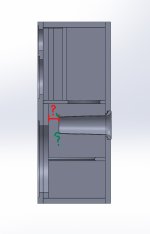
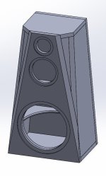
I have already used Vituix to simulate most aspects of the design including the baffle diffraction and enclosure volumes/port sizes. However, I am having trouble figuring out the ideal placement of the port based on internal geometry (not distance between room wall and speaker port). The cabinet is quite shallow, not leaving much room between the front baffle internal wall and where internal port entrance is as seen in the images.

I am wondering whether this will be enough room (~1.5 inches from port to wall) or if moving to an elbowed port will be necessary. If anyone has experience/ideas for the internal port clearances or suggestions as to what I can do differently please let me know. Thanks!

Attachments

  • Screenshot 2024-05-04 173050.jpg
    Screenshot 2024-05-04 173050.jpg
    36.6 KB · Views: 113
  • Screenshot 2024-05-04 174217.jpg
    Screenshot 2024-05-04 174217.jpg
    49.7 KB · Views: 115

Small Value MF Resistors for Stepped Attenuator?

I'm aiming for around 5k total resistance and around 78dB attenuation in a 47-step, 46-resistor attenuator.

The bottom values are challenging ones. 0.67, 0.12, 0.15, 0.17, 0.2, 0.25, 0.3, 0.32, 0.45, 0.47, 0.62, 0.91, 1.15 Ohms). I can find some, but for others the selection is mostly wirewound and MOX.

Are there any 1/10 to 1/4W metal film resistor kits that focus on small values like these?

Computer monitor output super noisy compared to phone output!

I recently upgraded my computer monitor to a koorui monitor and my amplifier I use for my speakers to a TPA3116 however when I plug it into my computer monitor audio output I get a horrible electronic stuttering wirring sound which is horrible for the ears especially when the audio is at a low volume. When I plug in the amp to my phone however, that noise is not there and there is a very soft hiss which I was expecting anyway. How can I fix the horrible noise from my computer monitor?

Help me chose between those 2 amplifiers please

Hello. My no-name amplifier burn out by some reason, but it was not quite good, as well was made with so-so transistors ( TIP41C ), so I wish to get a bit better one and with a higher output.
I stumbled upon these 2 which seems good choices, at least by looking at similar amplifiers. I aim highest quality possible for like 40-50 bucks.
Please help me decide ( if u have something else on mind please poste it as well - all suggestions is welcome )
So :
https://www.ebay.com/itm/3256821122...-8e35-e65a121c59e3|iid:1|vlpname:vlp_homepage

or
https://www.ebay.com/itm/1561016332...-8e35-e65a121c59e3|iid:1|vlpname:vlp_homepage

Thank You in advance guys.

DIY surround speakers

I know, I know. This should be a topic that is well covered. Except I have looked and although there are references to surround use for speakers, e.g. the Fountek FE85 powered Quark, I cannot seem to find a thread that suggests / discusses a rather good, affordable HT setup.

I am tempted by Paul Carmody's Overnight Sensation based solution. Misc Home Theater at https://sites.google.com/site/undefinition/home-theater-speakers
I like the Voxel Sub - or at least I expect to because I have built an Isetta and I'm just blown away by what the Tang Band W5-1138 can do!
He has designed a centre channel that is usefully dinky, using the Hivi B3N mid units and T20 tweeter.
Then it is a pair of OS MTMs for the main front L+R and a pair of OS TMs for the rear pair.
This seems like a nifty and affordable setup and I would like to build them all using the T20 tweeter so they all look and voice the same. I also like the idea of gently but securely screwing a tweeter down rather than hammering it into a hole a la Dayton! However I am having difficulty finding the T20 crossover designs for the MTM and TM. The only link for them is to the Meniscus site which is now defunct.

I already have a pair of C-Notes and like them. They are in my computer room / office system.
I would happily build some more as rears, even though they are more expensive than the OSs. There is a center channel design for them too, although it is a bit big for my needs, but what to do about the main fronts? More C-Note MTs and just turn up the bass? Not the preferred option.

Any other suggestions for an affordable DIY surround speaker package?

Making my own boxes is not a problem. I have tools that produce sawdust really fast!

Question about connecting power capacitor(s) to a car amp.

** The Backstory **

Before I can get to my questions, I have to give you some back story first.

Many years ago, I used to attend the yearly HAM Fest in my area. Every year there were hundreds of people selling literally thousands of nearly identical capacitors. Each capacitor was the size of a Tall Boy can of beer. The going price for these capacitors (from any vendor) was $1.

I've always assumed the capacitors originally came from the phone or power company. Probably because 1) there were so many of them, 2) there were so many people selling them, and 3) they were all the same size, shape, and being sold for (or, basically being giving away for) the price of $1.

Other than the size, shape and cost of these capacitors, the only other identifying information I remember was the number 470. I can’t tell you if that was the rated Voltage, the number u-Farads, or the number of corn flakes in a box of Wheaties.

Years later - when car stereo power capacitors hit the market costing multi $100’s a piece – I started to form a thought...


** Assumptions **

For the purposes of this discussion assume there's a car amp involved, and the car amp in question is 1000 Watts.

Also, let’s assume that the value of 470 was referring to the cap's maximum voltage rating of 470V (which I think was the case).

And finally, remember, I don’t know the actual value of the capacitance, so feel free to use a value you think fits..


** The Questions **

Question 1: With a rating of 470v, could these caps be repurposed to supply base power for the 1000w if they were conventionally connected between the car battery and the power amp supply voltage input?

Question 2: Assuming the car amp is 1000w and has a reasonably realistic rail voltage for the CMOS output stage of, say 200v (feel free to substitute a better value here as well). Could the caps described above be repurposed to supply oomph to the amp if they were wired directly between the power rail and ground?

Question3: In question 2, how much would having a second 200V plus DC power supply connected directly to the power rail help the sound?


Thanks for reading all this !!

Help explain weird waveform by i2s DAC

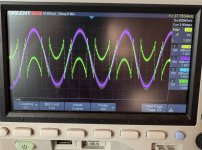
Hi, I'm working on a 2 in 6 out crossover for my audio system. I have a wondom apm2 with 4 dacs + 4 i2s out, so I had to add an external dac as well (https://www.audiophonics.fr/en/dac-and-interface-modules/dac-pcm5102mk-i2s-p-10551.html).

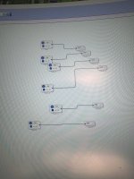
Tried setting up a 500hz test signal on all outputs in Sigma Studio and got this. dac{0,1,2,3} look like the purple while dig{0,1} look like the green.

Any clues why this is?

Attachments

  • IMG_1877.jpeg
    IMG_1877.jpeg
    506.3 KB · Views: 76
  • IMG_1876.jpeg
    IMG_1876.jpeg
    427.2 KB · Views: 75
Projects by fanatics, for fanatics
Get answers and advice for everyone wanting to learn the art of audio.
Join the Community
507,706
Members
7,885,130
Messages

Filter

Forum Statistics

Threads
406,077
Messages
7,885,130
Members
507,706
Latest member
thatchacha10