For Sale HUGE LOT VINTAGE transistors MOTOROLA Bipolar Transistor PNP Amplifier/Switch 80V 10A 2-Pin TO-3 2N3790 TEXAS Instruments

Don't know exactly what is in the lot.
$99 or best offer.

MOTOROLA 2N3790 Bipolar Transistor PNP Amplifier/Switch 80V 10A 2-Pin TO-3 (1PC)
2N3772 NPN PLANAR SILICON TRANSISTOR BY MOTOROLA
Transistor MOTOROLA TO-3 2N5631/2N6031

LOT VINTAGE transistors MOTOROLA Bipolar Transistor PNP Amplifier/Switch 80V 10A 2-Pin TO-3 2N3790

Attachments

  • 20230808_102302.jpg
    20230808_102302.jpg
    629.6 KB · Views: 200
  • 20230808_102304.jpg
    20230808_102304.jpg
    687.6 KB · Views: 198
  • 20230808_102306.jpg
    20230808_102306.jpg
    751.6 KB · Views: 180
  • 20230808_102307.jpg
    20230808_102307.jpg
    760 KB · Views: 175
  • 20230808_102309.jpg
    20230808_102309.jpg
    721.2 KB · Views: 179
  • 20230808_102312.jpg
    20230808_102312.jpg
    630.1 KB · Views: 167
  • 20230808_102317.jpg
    20230808_102317.jpg
    692.1 KB · Views: 160
  • 20230808_102318.jpg
    20230808_102318.jpg
    760.3 KB · Views: 155
  • 20230808_102320.jpg
    20230808_102320.jpg
    747.7 KB · Views: 217

15" driver query

Time to rebuild the stereo subwoofers.
Two simple 150 litre sealed boxes. In one I'll use a Cerwin Vega Vega15-4 because I have it but I'm going to need something in the other box of similar specification
Size is set by WAF and the secondary function is as stands for the tops
As yet I don't have an amplifier of suitable high power but by the time the boxes are built I should have
There doesn't seem to be mucxh around in Australia at the moment and I don't really want to spend $800- on a driver but I can't see any currently available $200- woofer matching CV
It seems that I have a choice between the SBA 42FHCL or one of three Dayton subwoofers and I can't seem to be able to choose.
DSP would be handled by the Behringer if needed as I do want some SPL at or around 16Hz although Max SPL I don't need too much really, 95 to 105 will match the tops ability. Help and opinions and any cheaper alternatives. All the other 15s in the shed are midrange drivers

Low Pass Filter on Class-D amp input - filter resonance control

I have often seen discussion about using negative feedback tapped from after the output filter to keep it from ringing when the load impedance rises, causing the characteristic rise in frequency response, and it seems like a good way to make sure the output filter does exactly what you want it to do. But it also involves added complexity and cost.

Would it not be potentially simpler to use an analog lowpass filter prior to the amp's input at just above 20kHz to prevent the amplifier from driving the output filter at ringing frequencies? Perhaps augmented by an additional notch filter if a deeper cut is needed in the frequency range near output filter ringing.

Advice for replacing speaker drivers in midcentury consolette

Hey everybody,

I'm doing a restomod project on a 1959 Sears consolette. It's cool-looking but the electronics were low-end even when new, particularly the speakers. It has a cabinet that contains a cheap Crescent record changer, a Warwick-built tuner/amp, and a single 6X9 speaker for the left channel. This was connected by a plug-in wire to another 6x9 extension speaker in a box only slightly larger than the driver itself. Both drivers run in free air, with no enclosure or back. I've got good quality electronics in place, and need to do something about the speakers, which sound terrible, more than anything due to the complete lack of output below about 200Hz due to the rear wave cancelation from those drivers flopping around in open air.

Login to view embedded media
I've found that lots of those old console woofers can sound pretty good with an aperiodic subenclosure, but due to the size of these cabinets that's not an option here.

I've considered

  • building an adapter board to mount a smaller, decent quality driver in place of the 6x9s and use a piece of PVC to make a subenclosure, maybe with a 3.5" or 4" driver, but lots of trial and error here.
  • replace the 6x9 with a higher-quality 6x9 car speaker - still not going to have any bass but the rest is probably going to be better.
  • Use the adapter board to fit a smaller full-range driver (no subenclosure) and augment the bass with a small onboard woofer in a subenclosure. I have a space about 5x6x12" inside the cabinet that I could use for that, and have access to an amp channel with crossover and DSP to drive it. This is of course more expensive and complicated, and I'm worried the woofer may interfere with the record changer it's going to share the cabinet with, which has a stamped steel chassis and is just sitting on some bedsprings.

What's the thinking, any one of these approaches sound better than the others? Or something I'm not thinking of?

Bedini 45/45

Hi, I may be purchasing this amplifier. Other than the handles missing it looks to be in pretty good shape. Service was performed on it a year ago or so. I would appreciate any comments on the service performed and the inside of the amplifier. Thx!

Attachments

  • ABC2F004-1F7D-4876-83E5-8993A384DA3E.jpeg
    ABC2F004-1F7D-4876-83E5-8993A384DA3E.jpeg
    358.7 KB · Views: 197
  • A48FEB80-2A00-4A58-A9DB-09F8457D4449.jpeg
    A48FEB80-2A00-4A58-A9DB-09F8457D4449.jpeg
    326 KB · Views: 203
  • F27A8796-D914-4D6F-952D-5B3AAA68438F.jpeg
    F27A8796-D914-4D6F-952D-5B3AAA68438F.jpeg
    106.5 KB · Views: 194

Looking for calibrated mics and DATS recomendations

Hey all,

I think I am done building stuff with traced files and want to start using a mic to get FRD files. Does anyone have a recommendation? Budget is around $150. I cannot justify over that for the amount I will use it. I do know they are only good for 5 years or so. There are a bunch of them on Parts Express and honestly I do not know the difference. It would be nice If I could use them to make FRD files of ported units.

I saw there is a way to create such a file but you need to have the time alignment correct and that this requires a secondary part. I think this is best. If I am going through all the trouble then I would like to be able to create FRD files for ported subs.

Secondly, it is worth buying a DATS system? Are DATS zma files more accurate than what is posted by the makers online? I do understand manufacturing variables but are they far enough off to make a serious difference in the sound?

I get how a company would fudge their FRD graph to get some more sales. I have seen quite a few drivers come no where near what the manufacturer graph claims. This is why I am doing this. Sick of building a whole unit and not getting what I expected.

Well let me know what you recommend or what you use that has been working out well for you. Thanks everyone.

DSP crossover only GEQ avaiable, strategy for speakers

Trying to learn DSP crossover when you have only GEQ. Waveguide plus midwoofer crossed at ~2kHz:

  • how to calculate a god HF lift?
  • use nearfield plus lets say 1 meter measurements?
  • no autotune in eg REW? all manually by trial and error?
  • what about step response and tweeter delay?
  • better use low order and match acoustic slopes?
  • Bessel, Butter, Linkwitz slopes for crossover 6-48dB
The fastest method.

Example hardware:
it has autotune build in but I think it will not work.

1716272939747.png

LKS MH-DA004 DAC as new!

Very....Very nice DAC that will be sitting on the shelve as my new DEQX PRE8 has arrived.

It has the upgraded USB input

Dual ES9038pro DAC (Digital-to-Analog Converter)​

  • Dual mono-mode ESS ES9038pro chips
  • Ultra-low-jitter 82fs clock at 100 MHz
  • Up to 13 groups linear power supply for different circuit part
  • Discrete shunt power supply for analog output part
  • Discrete circuit for I/V and LPF circuit
  • Cardas rhodium-plated RCA output connector
  • Furutech AC power socket
  • 2 I2S Input Ports: RJ45 type and HDMI type for I2S/DSD source input
  • Amanero Combo384 USB card: DSD64, DSD128, (Windows, DSD256, DSD512), PCM44.1K~384K
  • AES/EBU, COAX, BNC, OPT support: 44.1K, 48K, 88.2K, 96K, 176.4K,192K S/PDIF input (DoP acceptable)
  • XLR: 5 Vrms
  • RCA: 2 Vrms
  • Digital Volume Control: 0–127 dB (0.5 dB step)
  • Large VFD display
  • THD: <0.0003%
  • Dynamic Range: > 125 dB
  • SNR: > 120 dB
  • Dimensions: 17.3 x 12.6 x 3.5 in (440 x 320 x 90 mm)
  • Net weight: 17.2 lbs (7.8 kg)
  • With original box
1716366739045.png

A very quick question about active devices used in cap multipliers _ why darlingtons are so rare ?

Good morning everyone I have a simple question about choosing the transistor to use in a cap multiplier
If I understand correctly it is good to have a device characterized by a high hfe
How come I see cascades of bjts and practically never darlingtons with hfe=1000 ?
Are there any problems that I don't know about using a single Darlington that provides the same hfe as two or three bjts in series? thanks everyone for the help

GK1 upgrades

good afternoon after a long absence.

I have finally opened up my GK-1R after many years and looking at 4x 40uF Audiocaps and BC560 transistors purchased years ago in a group buy by West but waiting to install.

Does anyone have any photos of these much larger caps fitted? And given the preamp is nearly 15 years young, any other recommendations to do at the same time?

thankyou,

Does not make any sense HELP!!!

Hello everyone,
I have a strange phenomena that just does not make any sense to me. - ANY IDEAS!!!

I use high level input from the output of my amplifier (211 valve amplifier) speaker terminals to 2 subs, the leads running in parallel, and are identical.
I use two separate BKELEC sub amplifiers that are identical and take high level input with a Speakon connector.
I have a dedicated mains supply with a dedicated consumer unit. I have 8 MCBs running off 2 RCDs (4 MCBs each) Each MCB feeds a single 13Am UK socket with low impedance cable from the consumer unit (30A twin and earth) for convenience of the explanation I have called these socket ABCD and EFGH as they represent the 2 banks of 4
I have painted the sub amplifier boxes (they are not installed in the subwoofer) black and Yellow, for the convenience of the explanation I will call them BKB and BKY they are identical units.

Originally BKB was connected to socket A, and BKY to socket D

When I accidentally swapped the plugs on reinstalling I put BKB to D and BKY to A and I got a very loud SSSSHHHHH noise ARRRGHH what has failed now I thought. But after extensive testing I can confirm that this ONLY occurs with the earth cable of socket D connected to BKB.

no other socket does this
it does not matter if the BK amp is on or off
all physical mains and speakon leads repeat this behaviour
I can disconnect BKY and it makes no difference
testing impedances on BKY and BKB shows no difference
testing impedance on earth on socket A and D measures the same to a consistent reference point

ANY ?IDEAS?

For Sale Cerwin Vega Vega 154

I haven't been able to find a second unit so selling this to help fund a pair of something suitable.
Minimal usage due to old WAF
Pick up in Geelong VIC Australia and post by negotiation
A great Old School musical sub.
Low Fs and good power handling Fs 23Hz and 19mm X-Max
Optimum box size is big at ~180 litres and low tuning to 22Hz
Will work sealed in 50 to 90 litres tho and the bigger the better up to Q-0.55
Asking $350- plus P&P
Slightly negotiable Re pick-up and cash payment
Pictures are available on request

Cub Sandwich

Hello all. My first driver for the Tiny40s project has arrived, and she looks like a lil monster. The most relevant test box is 4L internal, 2x passive radiator in fibre reinforced plastic sandwich and it's worthy of a project of its own. I'll take this opportunity to add something missing in my rig. A mini porch type PA/DJ/Karaoke system

Since such events tend to start with some energetic wine downs and end with a drunken coolie uncle dance or two, she will have to be heavy duty and survive potential knock overs and things

Having learnt a lot from this forum, maybe I can present something in return that could potentially add to the many ways of making cabs

I am inclined to use foam as the core but will consider ply instead if there is enough interest in that. So guys, let me know what's more interesting, ply or foam?

Thanks and regards
Randy
  • Like
Reactions: JMFahey

KAV-300 CD spin but stops

SOLVED
Fix: replaced the laser

Hello Ladies and Gentlemans

I have a Kav-300 Cd player and when putting the cd in, the cd mechanism start spinning the cd and after 5 sec, it stops.

The player hasnt been used for many years and i suspect there are a few bad capacitors.

I tried to find the service manual and i cant find the correct one.

Any help?

Attachments

  • Screenshot_2024-05-09-15-54-45-53_0ce57feeccaa51fb7deed04b4dbda235~2.jpg
    Screenshot_2024-05-09-15-54-45-53_0ce57feeccaa51fb7deed04b4dbda235~2.jpg
    163.6 KB · Views: 91
  • Screenshot_2024-05-09-15-54-31-62_965bbf4d18d205f782c6b8409c5773a4~2.jpg
    Screenshot_2024-05-09-15-54-31-62_965bbf4d18d205f782c6b8409c5773a4~2.jpg
    445.7 KB · Views: 103

Cinemag SUT

Hi All. I've been lurking on this site for awhile and just set up an account. Hope to be a consistent member.

Anyways, I have a Parks Audio Budgie tube preamp that I LOVE. I was to try out MC cart (Hana SL) to replace the Exact 2 on my Rega Planar 3 which is approaching 1,000 hours of use. To do this, I need a Step-up Transformer. I missed the opportunity to get the Budgie Cinemag SUT that Parks Audio sold for a few years. I read that someone on this site may make a Cinemag based SUTs (or another design even)? I would love to purchase one. Does anyone know anyone that makes these as a side hustle?

Thanks!
Mike

Where to position sound system to avoid room modes/standing waves?

So we've been doing several events recently with our system composed of 4 keystones, 4 hd15s and 2 syntripps. In most of the venues we have no issues at all but 2 of the events where in long narrow spaces and I found we where really struggling to get any bass to project any further than a few metres in front of the system. For context the systems where placed front centre 2-4m from the back wall facing straight forwards.
Now we normally don't struggle to have other places shaking but for these 2, we has no end of problems trying to eek anything out.

So the question is, how can I avoid this in the future? Would setting up more towards one side and toeing them onwards be an amount be enough to stop any standing waves or room modes? Are we placing the system too far from the back wall rather than closer and making use of the additional gain you would get from the rear wall/corner.

Does this sound like a standing waves/room modes issue? I know you can't eq it away or use delays as I tried pretty much everything I could think of bar trying to shunt the massive stack about to fix it!.

Tia

Does this variant of Zen Variant 1 work?

Hello everybody! This is my first post here, and also, I am very new to the hobby of electronics so please bear with my misunderstandings.
I am thinking about implementing Figure 5 from Zen Variations 1 but with my own twist.
https://www.passdiy.com/project/amplifiers/zen-variations-1
zenlite_9.png

The twist is that instead of using a lamp and the whole circuit between the lamp and positive voltage as in Figure 5,
I will be using a benchtop PSU with constant current at 2A and raising it to 12V.
So the positive of the PSU will be where the lamp is instead of the lamp.
I think 12V 2A matches the conditions specified in the article but I am not entirely sure.
I want to know if this substitution is possible.
The article says you need a constant current source but
I am very new and unsure whether my benchtop qualifies as the 'constant current' source needed.


I have some more questions.
The output in Figure 5 is just a node hanging off to the right.
I have an 8 ohm full range speaker. Do I attach the speaker from 'OUTPUT' to ground?
The input in Figure 5 is just a node hanging off to the left.
Do I attach the positive of my PC audio cable splitter to 'INPUT' and the negative to ground?
(These grounds are all going to the negative of my PSU).

'The electrolytic capacitors should be voltage rated at the supply voltage, which in this project can vary from 40 to 80 volts DC.'
Also, I see my two electrolytics are rated at 25v and 35v, higher than the PSU's 12v but lower than the article's supply voltage at 40v-80v.
Could this be a problem?

Thank you.

I Want To Have A Law That Prohibits Cell Phone Screen Shots In TV Shows

Or at least if you have a shot of a cell phone screen then you have to blow it up several times and hold it longer so that people can read it.

I don’t know about you, but I can’t read the ******* cell phone messages. The text is just plain too small. Maybe if I was sitting very close to the TV I could read it. But that’s not where I usually sit.

On top of that they always tilt the cell phone. Sometimes as much as 45 degrees. So now I have to try to read it sideways instead of straight up and down. I don’t read books or newspapers tilted. My brain expects the image to be upright.

And to make matters even worse, they only leave the shot on for 1 to 2 seconds. So the other part of my new law is that you have to leave the cell phone screen shot on for at least 5 to 10 seconds. Then maybe I'll have at least a chance to read it.

My wife is a faster reader than I am, so sometimes she can catch the message. Then I have to ask her what it said and we have to stop the TV program so that she can tell me. Doesn’t make her happy or me either. I don’t know if this is a problem for anyone else or not, but it sure is for me.

There didn’t use to be a problem before cell phones, but now there is. So if this is also a problem for you maybe you can help me get a bill passed through congress to put an end to it. There really has to be a law to fix this.

How loud and low should I tune my sub?

About to build my first DIY active home sub, not decided fully on 10" or 12" yet. My dad had 2 8s about 25yrs ago in his truck and said that was plenty, so he's not sure how big he'll let me go because I'll shake the house lol... I'm planning on putting this into a car when I get one, so I want to keep it pretty small.

If someone could give me a quick run down of how loud and low I should be aiming for that'd be nice. Planning on using either the rockford P1S4-10 or P1S4-12, but I'm leaning towards the 12 for the bit extra low end. Ideally I'd use a 2.5ft^3 ported box tuned to 30hz, that's what I'd tuned for initially, but then I realised that a car would be really impractical with such a big box.

Putting 200W into the 12" model in a 1.2ft^3 box tuned to 35hz, it's getting 101db at 30Hz and it peaks at 109db from 40-70hz. All measured at 1m. Using a 4" port, velocities are under 20m/s even at 300W, so chuffing isn't going to be a problem. Just wondering if that'll be enough to feel it in your chest and get a good rumble when watching movies or listening to music.

JFET model generator

JFET spice model generator

It might be not the most suited place to post it here, but since this is my favorite section in diya and we are exclusively using FETs for amplifications in our projects so I decided to share something that I developed during the weekend and I hope it will be helpful to some of you.

Before I build an amp I like to simulate it first, and often I need a JFET model with a specific Idss. So I build a simple web-based app that uses some predefined templates and calculates and modifies beta and Vto to get a specific Idss.

Here is the link: JFET calculator <<<<<<<<<<<<<<<<<<<<

Please feel free to share your ideas, improvements, etc...

So how I calculate beta? From the equation below:

beta = Idss/Vto2

How about Vto? It's a bit more complicated:

idss-vto.png


Unfortunately, Vgs(off) is not exactly Vto, Vgs(off) is a lower value than Vto, actually, I haven't found any specific definition of what Vto is, apart from "Threshold Voltage". Vgs(off) is a Vgs voltage that reduces Id to 0.1uA at Vds=10V. Someone mentioned that Vto might be... Vgs that reduces Id to 1% of the Idss? So I had to get Vto from the transconductance curves from the datasheet... well... roughly.

As Mark Johnson pointed out the above plot is a straight line, but it is on a log scale, to be precise it's a Log-log plot so the dependency between Idss and Vto is a power function: Vto = k * Idssm - k and m are calculated from points (Idss1, Vto1) and (Idss2, Vto2).

The key to having a reliable Vto is to properly specify these two points that define a straight line in these log scales, for each transistor model (across the range of Idss) there are going to be different points.

For 2sk170 I have chosen:
1) Idss: 1mA, Vto: -0.2V
2) Idss: 10mA, Vto: -0.55V

For 2sk246:
1) Idss: 1.3mA, Vto: -1.25V
2) Idss: 5.6mA, Vto: -2.8V

Idss is specified at particular conditions, like Vds=10V, for higher Vds we get slightly higher Idss. Depending on the lambda we get also different values.

If you have ideas on how to modify other values please let me know. I have also looked into built-in LSK170 (A, B and C) models in LTSpice, but I can't see any clues that lead to a conclusion.

No electrostatic screen on toroid

Ordered a audio grade transformer from James transformers and they forgot the screen. My OCD is killing me, very miffed, James even ignored my complaint. They are normally very good. The screen is normally a standard item in their products I think (didn't specify one before and it was included)

Convince me all is well, how vital to the audio experience is the screen, the noise is generated between the power lines and ground right?

Is the screen is built between the windings and connected to OV?

Can the difference be measured?

Odd B+ behavior

So, when the amp is power up (after 2-5 minutes of filament warm up for the 866A rectifiers), the B+ ramps up nicely to ~460Vdc, then immediately reverses back down and settles at ~180Vdc where is holds steady. I expected the B+ to stay steady at 460Vdc. One of the 866A rectifiers is lighting up a nice blue glow, the other does not. I tried switching the tubes and the blue glow stays with the socket. This tells me this is not a tube issue. I also tried new 866A tubes and the same behavior. The filament voltage measures 2.5Vac, per spec. My filament wiring config is attached.

What might cause the ramp down in B+ ?

Thanks

Attachments

  • PNG image.png
    PNG image.png
    664.9 KB · Views: 123

TPA3255 questions - Is 1.1A@50V the most I can get out of this or am I doing something wrong?

I have this amp: https://www.aliexpress.us/item/3256...t_main.69.3f611802EMT5Qe&gatewayAdapt=glo2usa

I am using an old PC PSU going into this DC boost: https://www.aliexpress.us/item/3256...t_main.63.3f611802EMT5Qe&gatewayAdapt=glo2usa

I have the booster set to 50V as tested with my multimeter. The amp is in PBTL mode (side note. there is no difference in SPL as measured with my iphone app in BTL or PBTL mode. DOes that sound right) The most I can pull in terms of amps is 1.1A. Shouldn't be be able to pull 150w @8ohms? and if i understand ohms law that would be 3A right?

I have tried this with a different power supply as well.

My goal is to see what the loudest usable volume is out of this amp before it sounds bad or maxes out my power supply or itself. I am using it as a bass guitar amp with a 4x12 8ohm cab.

I am using a looper pedal fed into a graphic eq pedal with everything cranked and there's no insane distortion. I threw another preamp in front of the graphic EQ. As i turned everything up I got more distortion. My SPL stayed the same (around 124ish) and yet my current draw was still 1,1A.

Where to position sound system to avoid room modes/standing waves?

So we've been doing several events recently with our system composed of 4 keystones, 4 hd15s and 2 syntripps. In most of the venues we have no issues at all but 2 of the events where in long narrow spaces and I found we where really struggling to get any bass to project any further than a few metres in front of the system. For context the systems where placed front centre 2-4m from the back wall facing straight forwards.
Now we normally don't struggle to have other places shaking but for these 2, we has no end of problems trying to eek anything out.

So the question is, how can I avoid this in the future? Would setting up more towards one side and toeing them onwards be an amount be enough to stop any standing waves or room modes? Are we placing the system too far from the back wall rather than closer and making use of the additional gain you would get from the rear wall/corner.

Does this sound like a standing waves/room modes issue? I know you can't eq it away or use delays as I tried pretty much everything I could think of bar trying to shunt the massive stack about to fix it!.

Tia

Protecting TL431 in a high voltage high-side current source

Hello, hope everyone is having a great weekend 😎

I'm designing a shunt regulator which is fed by a high-side CCS. My previous design uses a 5.6V zener as the reference for the pass mosfet; This works but current regulation is not so good due to zener noise. Also the zener needs a minimum of 5 mA current to control noise so there is power wastage in the feed resistor to the zener. Moreover this zener current bypasses the CCS and has to be regulated downstream by the shunt mosfet.

I redesigned the circuit as a text-book TL431 current source with the difference that it is floating at HV (partial schematic of the relevant section below). In simulation the current regulation is really good, within a milliamp, and the TL431 only need a milliamp to regulate - The design is so that the minimum current through it is around 1.2 mA, and peaks at 2.2 mA. This represents a very significant power wastage reduction in feed resistor R1.

Capture d’écran 2024-05-19 131921.png


At start-up when the output capacitor (not shown) isn't charged the device will see the full rectified voltage from the 45 uF input capacitor across its anode and cathode (350v peaks). To protect it and the mosfet gate there's a 18V zener that will get out of circuit when the TL431's AK voltage differential drops below the zener threshold - so it won't contribute noise in normal operation. I have seen this TL431 protection scheme in other circuits online but they were all "low-side", e.g. the TL431 anode was grounded. Will it work in my proposed circuit?

Also I read that the TL431 likes to oscillate when driving an external transistor. Some suggest a compensation capacitor between cathode and reference. Is it a good idea in the context of this circuit? I would think such a capacitor can mess with M2's gate/source capacitance and create more problems than it solves.

Lastly, are there no-no's I don't see with my beginner eyes?

As always, thanks in advance for any insights.

- Joris

DAC design based on ES9038PRO (Lumin)

As a student of electronics, my teacher want me design a DAC with ES9038PRO (dual chip)
With i2s input
I found that Lumin audio is designed a very good DAC in all their latest devices, but as they are new devices, we can't find a schematic.
I try to contact with Lumin to help me in this regard but no answer.

Attached data is what i get from Internet, from different sites.

If anyone can help me in this design.

Thanks in advance

Attachments

  • Screenshot_20231021-041021_Fiverr.jpg
    Screenshot_20231021-041021_Fiverr.jpg
    225.7 KB · Views: 491
  • dz02NjImaD0zNzc__src_60714-odtwarzacz-sieciowy-lumin-t2-audiocompl-fot8.jpg
    dz02NjImaD0zNzc__src_60714-odtwarzacz-sieciowy-lumin-t2-audiocompl-fot8.jpg
    78.6 KB · Views: 452

Confusion concerning Rdc/Re in AJHorn

Im new to building speakers. I already read the "Handbuch der Lautsprechertechnik" and rn im on The "Loudspeaker Design Cookbook". I tried to get my info there but didnt find what i was looking for. So: I bought a driver B&C 8BG51. I want to use it in a closed Box (Frequencyband 100-500Hz) because i already built a Bassreflex Speaker for underneath.
Online the Frequency Graph on B&C site looks like this

1714864380256.png


Now I calculated a box size for Qtc beeing 0.707 of 8.484l. If i now enter all the Data into AJHorn
1714864598748.png
1714864620955.png

i get this Graph:
1714864660899.png

which looks pretty underwhelming.
Now i found out, that the main Reason the Graph looks like this is that i Dialed in Rdc/Re of 5.1Ohm. If i was to dial in 8Ohm it would look like this:

1714864783076.png

which would be much closer to what i would have expected.
Can you guys tell me if i did a mistake in the Simulation or is that a common behaviour of Drivers under certain circumstances.

Cheers and a nice Weekend

Elias

Big thud on startup ACA and after 5 minutes one channel stops

Hello everyone,

I have finished my second ACA and this one has 2 problems. First one works great.
1) big thud in right channel on power up and. Both channels after thud emit the usual whining sound.
2) left channel goes silent after 5 minutes or so.

I checked all connections/soldering/continuity etc.

The amp runs slightly warm not hot like normally does.

Could it be the voltage is too high, spike (I use a voltage reg) although I took good care to keep it at or very near 12v

Any other suggestions?

Thanks

Assistance with Mordaunt Short Pageant Series 2

Hi All.
Sorry for my absence from the forum.
Had been caring for my mother, who recently passed away.

I was hoping for information & assistance with a pair of Mordaunt Short Pageant Series 2 Loudspeakers.
The owner finds that they no longer sparkle for her.
I played a familiar track on them and found they're a little dull sounding and lack sharpness across the range.
The 2 toggle switches on the rear are a little strange.
Both are set in the up position, but will not switch downwards.
I've put some force on them but they won't budge.
I was concerned not to put too much more force on them for fear of damage.

1. Are the toggles switchable up & down and which direction is flat & which is bright?
2. Do these toggles switch the path between direct & through the resistors?
3. Is it desirable to avoid the signal going through resistors, especially cheap ones?
4. If I leave them switched bypassing the resistors, then is it pointless replacing the resistors?
5. Is it worth replacing the electrolytic caps to poly or should I just get fresh reasonable electrolytic replacements?

I plan to remove and measure current caps, but thought I'd post first.
There is currently a single 10mfd & 2 x 5mfd's fitted to the x over.
thanks cliff

Attachments

  • Mordaunt Short Pageant Series 2 1.jpg
    Mordaunt Short Pageant Series 2 1.jpg
    341.7 KB · Views: 266
  • mordaunt short pageant series 2 label_z.jpg
    mordaunt short pageant series 2 label_z.jpg
    55.3 KB · Views: 229
  • Mordaunt Short Pageant Series 2 pcb 3.jpg
    Mordaunt Short Pageant Series 2 pcb 3.jpg
    549.9 KB · Views: 222
  • Mordaunt Short Pageant Series 2 resis 2.jpg
    Mordaunt Short Pageant Series 2 resis 2.jpg
    598.6 KB · Views: 213

Matching Drivers of different Impedance

Hi all,

thanks for all the assistance as always and apologies in advance if this is a silly/basic question.

I’m hoping for some assistance in matching two drivers of different impedance, a JBL 2446h (8ohm) and 2447j (16ohm). I had initially thought I could run these off two different channels of an amp as I understand that the two channels can work as separate amplifiers but is this a valid approach?
If so I guess I could use an xlr splitter cable from my x-over to achieve this but does anyone foresee any issues with proceeding like this?
Im struggling to find a matching 2446 or even similar 2” driver at 8ohm which is why I’ve been pushed to use this approach (my horns are designed for the 2446 so will be making my own adapter for the 2447).

If anyone has any suggestions / alternative options that I could explore I’m all ears!

Thanks,
Lawrence

LSK pre - BAF 2013

At the BAF2013 Mr. Pass presented a nice JFET preamp. Today I cobbled up a quick prototype of one channel to test its behaviour and it's very nice. I have a BL rated Toshiba JFETs so some values had to be changed and some parts added (P1 to set the DC offset at the output and harmonic content, caps in cascode voltage divider to improve HF extension a bit). Serious build with buffer added at the output will follow. For the time being here is the schematic and the PCB layout of the preamp (copper side view, 45x50mm) :

EDIT (Oct. 27, 2013): 'final' schematics and pic of built preamp are in the post #66

Attachments

  • LSKpre-sch.gif
    LSKpre-sch.gif
    6.7 KB · Views: 11,606
  • LSK-BAF2013-PCB.GIF
    LSK-BAF2013-PCB.GIF
    33.4 KB · Views: 10,150

Synq 3K6 service manual

Hello. I have this amp from years ago and it has always worked fine but a few days ago the left channel did not work and it damaged my column. I could smell burning. I have opened it and it has two blown fuses on the amp board.
I have checked the two transistors and they are shorted but it does not let me see which transistor it is. It has the identification erased. That is why I need the service manual to identify those components
If someone can pass it to me, I appreciate it. Thanks and regards

Digitally controlled analog shelving filter (low/high shelf eq)

Hello everyone,

I'm working on a project that's based around the idea of "digitally controlled analog". This project should include some basic EQ functionality to show the usefulness of other parts of the device.

Theoretically, a Baxandall style circuit should be perfect, so I went with the "Active / Single Bass Capacitor" variant from https://www.guitarscience.net/tsc/baxandall_2.htm#

My first idea of implementing digital control capabilities were digital potentiometers, which lead me to the same problem with massively distorted audio as described in this post from 2004: https://www.diyaudio.com/community/threads/digitally-controlled-baxandall.28022/
Given the age of that post, I'm curious whether nothing has changed over the last 20 years - at least I was using modern digipots that were designed for higher analog voltage levels: https://www.microchip.com/en-us/product/mcp41hv51
(The pots were powered with +/-15V and the voltage across them was never near their maximum.)

My next best idea would be motorized potentiometers, but I'm not sure whether dealing with motor control circuitry is worth it, considering their performance.

Since the values need to change in real time, preconfigured values that are switched by relays aren't really an option either - the zipper noise of digipots would already be prolematic.

The eq feature is too important for the project to be left out, but not important enough to go down another rabbit hole like vactrols...

Has anyone got another idea? Maybe in the form of a different digipot, a different eq circuit or a different way of adding digital control to existing circuitry. 🤔

Thank you all very much in advance!

For Sale Untested mystery lot (100+) Vacuum tubes -- GE Amperex RCA Raytheon Sylvania -- NH USA --

SOLD AS IS
I know nothing about them.
Please see pics.
$180 shipped USA

Attachments

  • 20231220_161108.jpg
    20231220_161108.jpg
    784.4 KB · Views: 303
  • 20231220_161109.jpg
    20231220_161109.jpg
    868 KB · Views: 302
  • 20231220_161113.jpg
    20231220_161113.jpg
    599.1 KB · Views: 253
  • 20231220_161116.jpg
    20231220_161116.jpg
    579.1 KB · Views: 255
  • 20231220_161119.jpg
    20231220_161119.jpg
    620.1 KB · Views: 252
  • 20231220_161124.jpg
    20231220_161124.jpg
    838.4 KB · Views: 236
  • 20231220_161125.jpg
    20231220_161125.jpg
    849.7 KB · Views: 316

Mixing and Matching Diaphragms and Compression Drivers

As the title states, I'm trying to understand more about the possibilities of swapping out compression driver diaphragms with different diaphragms. On another thread I was told that it can be done, and possibly some CDs have multiple diaphragms that can be used? But I'm finding zero information online. And I thought I should make a separate thread for this question.

The reason this question comes up is because I'm using coaxial drivers (B&C 12FHX76). This coaxial design shares the magnet, so I can't swap out the entire compression driver. But what if I can find other diaphragms that would work? Could I improve the unfiltered response of the CD?

I am a noob as far as compression drivers, so I don't know how much impact the diaphragm has on the CD's performance vs how much of an effect the internal structure has. I suppose it is entirely passible that changing the diaphragm will not have much of an effect, but I want to ask. If I had parts laying around I'd swap them and see. But unfortunately I don't have any parts to play around with.

If we find that the diaphragm makes a difference, what is the chance that a diaphragm from one manufacturer will fit and function well in a different manufacturer's CD? I don't know if the curvature of the diaphragms is going to be the same, and it seems to me that the internal clearances are important. But at the same time, I suspect that physics involved forces the internals to be pretty similar?

I've seen some designs using polymer diaphragms that seem to perform quite well. And then there is the Eminence carbon fiber diaphragm. It'd be sweet if I could mix and match to fine tune my driver's performance. But will it work?

Power Supply for Ivey's Phonostage and others

So I am working on something that can be used for Ivey's 2N2222S phonostage, the opamp Hagerman Bugle phonostage and Pass Labs B1 with Korg triode tube preamp.

I built Elliot Sound Products cap multiplier out of spare parts for a 24V output and have a few questions if anyone has any comments or opinions.

I attach a schematic.

And here are my questions:

1. I don't understand how the voltage output is adjusted. Can anyone give me a hint? I'm useless with transistors.
2. What I end up with rectified voltage is always a mystery to me. The overspec'd transformer and bridge gives me 28.8Vdc. Where I guess I would have expected 31.2V [(23VAC x 1.41) -1.2]. Oh well I was hoping for 27V rectified volts
3. Am I on the right track for a good power supply for a phonostage or preamp?

Thanks much,
Dan

Attachments

  • Screenshot 2024-05-20 at 9.52.03 PM.png
    Screenshot 2024-05-20 at 9.52.03 PM.png
    69.4 KB · Views: 93

BeePre (gen1 - 300B) volume control

Hi all,

I got a BeePre gen 1 in for repair. It has the upgraded switched attenuator with two switches, one for coarse and one for fine control. The schematic I have does not include the upgrade. On the attached image, the two resistors noted by red arrows, are burned black and I'm unable to read the value. One measures 820 ohms and the other is 940 ohms. From what I can by blowing up the pic, they appear to be 1K parts. Can anybody confirm that for me please?

Part 2: What could possibly cause a resistor in a volume control to get that hot?

Customer says the unit ran hot, maybe the regulators boards?

I'm not familiar with this unit, so I don't want to just plug it in. It has some age on it, so I'm going to replace all of the electrolytic caps.

BTW, the contacts on the switches on the actual unit (not in the pic) were black and when I sprayed some contract cleaner on them, the stuff liquified and was a tar-like material. I removed as much as I could, but I could only get the wipers clean.

Any advice will be appreciated.

Attachments

For Sale Morel MW1075

I have a couple of these trialed then put aside, long ago. So long, when I tried to take pics, my finger went through the hardened foam. I found foams that should fit, but are not original, and may themselves of got lost now. Miss-shaped is more likely, as they were in a document envelope.
I really need to find these a home. They still demand $200 each, new. These are almost certainly the originals, not the later factory. I'm not going to price them though. I want to see them used, but they need a massive box, or an OB project. After fixing them.
Anyone who's gives time to the forum, can have them.

I think the foams were actually listed as infinity, and likely a search result here.
  • Like
Reactions: ianbo

Einstein CD Player Model "The-Last-Record-Player" - Service Manual wanted

A friend of me is looking for a service manual for DAC and power supply units (Einstein made) so as the KSS-240A (and in some devices of this model KSS-213B) mechanism (SONY made).
The last wanted must actually be easy to find as long as one know, in which HiFi system or single cd player model from SONY is the same mechanism.
Thank you very much for an advice.

Attachments

  • Einstein-The-Last-Record-Player-package-VII.jpg
    Einstein-The-Last-Record-Player-package-VII.jpg
    629.1 KB · Views: 93
  • Einstein-The-Last-Record-Player-package-VI.jpg
    Einstein-The-Last-Record-Player-package-VI.jpg
    631.8 KB · Views: 77
  • Einstein-The-Last-Record-Player-package-VIII.jpg
    Einstein-The-Last-Record-Player-package-VIII.jpg
    574.3 KB · Views: 82
  • Einstein-The-Last-Record-Player front-II.jpg
    Einstein-The-Last-Record-Player front-II.jpg
    98.1 KB · Views: 69
  • Einstein-The-Last-Record-Player package-I.jpg
    Einstein-The-Last-Record-Player package-I.jpg
    30.1 KB · Views: 65
  • Einstein-The-Last-Record-Player package-IV.jpg
    Einstein-The-Last-Record-Player package-IV.jpg
    32.3 KB · Views: 66
  • Einstein-The-Last-Record-Player package-II.jpg
    Einstein-The-Last-Record-Player package-II.jpg
    47 KB · Views: 68
  • Einstein-The-Last-Record-Player package-V.jpg
    Einstein-The-Last-Record-Player package-V.jpg
    82.7 KB · Views: 72
  • Einstein-The-Last-Record-Player package-III.jpg
    Einstein-The-Last-Record-Player package-III.jpg
    86.2 KB · Views: 75
  • Einstein-The-Last-Record-Player front-I.jpg
    Einstein-The-Last-Record-Player front-I.jpg
    77.5 KB · Views: 76
  • Einstein-The-Last-Record-Player KSS-240A-I.jpeg
    Einstein-The-Last-Record-Player KSS-240A-I.jpeg
    46.9 KB · Views: 72
  • Einstein-The-Last-Record-Player KSS-240A-II.jpeg
    Einstein-The-Last-Record-Player KSS-240A-II.jpeg
    77.3 KB · Views: 82
  • Einstein-The-Last-Record-Player KSS-240A-III.jpeg
    Einstein-The-Last-Record-Player KSS-240A-III.jpeg
    78.5 KB · Views: 74
  • Einstein The last Record Player KSS213B.png
    Einstein The last Record Player KSS213B.png
    88.9 KB · Views: 72

Musical Fidelity Elektra E601 or E60 CD Player Service Manual

Hi,

Anybody out there with the service manual for the CD player
Musical Fidelity Elektra E601
(I assume that E60 will do as well)

My CD player refused to start up yesterday. There is some noise as if something in the transport spins up, the display comes alive for 0.5-1sec or so then it goes off again and the cycle repeats.
Today I left it flashing on and off for some time and then it came alive. It plays discs and all seems to be fine.

All this happened when I opened it to inspect. Now it is hard to fix if it is not broken. Still I am pretty sure the issue will come back.

I have contacted MF some time ago about the schematics/service manual but they refused to send anything...

So if anybody has anything could you please send it to me?

Schematic for Roksan Caspian M1 Monoblock (Mono Power Amplifier) wanted

Who can upload the schematic diagram ?

Attachments

  • roksan_caspian_m1_monoblocks-4.jpg
    roksan_caspian_m1_monoblocks-4.jpg
    89.4 KB · Views: 129
  • roksan_caspian_m1_monoblocks-3.jpg
    roksan_caspian_m1_monoblocks-3.jpg
    44.4 KB · Views: 103
  • roksan_caspian_m1_monoblocks-2.jpg
    roksan_caspian_m1_monoblocks-2.jpg
    46.8 KB · Views: 96
  • roksan_caspian_m1_monoblocks-5.jpg
    roksan_caspian_m1_monoblocks-5.jpg
    41 KB · Views: 96
  • roksan_caspian_m1_monoblocks-6.jpg
    roksan_caspian_m1_monoblocks-6.jpg
    31.9 KB · Views: 99
  • roksan_caspian_m1_monoblocks-rear-II.jpg
    roksan_caspian_m1_monoblocks-rear-II.jpg
    103.7 KB · Views: 99
  • roksan_caspian_m1_monoblocks-rear-III.jpg
    roksan_caspian_m1_monoblocks-rear-III.jpg
    66.3 KB · Views: 108
  • roksan_caspian_m1_monoblocks-rear-I.jpg
    roksan_caspian_m1_monoblocks-rear-I.jpg
    85.3 KB · Views: 126
  • roksan_caspian_m1_monoblock-PCB-III.jpg
    roksan_caspian_m1_monoblock-PCB-III.jpg
    93.6 KB · Views: 277
  • roksan_caspian_m1_monoblock-PCB-I.jpg
    roksan_caspian_m1_monoblock-PCB-I.jpg
    90.2 KB · Views: 158
  • roksan_caspian_m1_monoblock-PCB-II.jpg
    roksan_caspian_m1_monoblock-PCB-II.jpg
    92.8 KB · Views: 152
  • roksan_caspian_m1_monoblock-PCB-IV.jpg
    roksan_caspian_m1_monoblock-PCB-IV.jpg
    87.4 KB · Views: 146
  • roksan_caspian_m1_monoblock-PCB-toroidal.jpg
    roksan_caspian_m1_monoblock-PCB-toroidal.jpg
    61.8 KB · Views: 113

Powering 4 x Nilai500

1. I need to drive 2 x 4 Oms per channel (bi-amp per channel). I have ~800W toroid with quad output / +-65V x two linear power supplies. Would these PSUs be sufficient? Is there anything special I need to implement to decouple amp modules from each other 🤔?

2. Re: Input Voltage Driver Referenced to V-
Just to double check the connection: +Voltage Driver source must be connected to amp module; - Voltage Driver should be connected to V- (-65V); am I right?

Thanks a lot in advance!

New Headphone amp needed

Hi all,

First, a confession - I've killed my O2 headamp after many years of excellent service. Very stupidly I plugged the wrong power jack in and rather than receiving 15V ac it got 21V dc off an SMPS. The power led still lights but no sound out, I haven't opened it up yet to see what's fried...

So, two questions that I'd appreciate some adivce on:

1) What am I likely to have killed in the O2 and given it's age, is it worth reviving?

2) If the O2 is not state of the art these days, recommendations for a new headamp. My headphones are HiFiMan Sundara, 32 ohm IEMs so fairly current hungry. I don't need the amp to be portable and don't need an integrated DAC. I prefer revealing, uncoloured very low distortion amps, is there anything out there taking advantage of the newer OPA 16xx series? Valve amps need not apply, just my preference. 🙂

Thanks in advance for all contributions

My KEF 107/2 experience so far

Well a while ago I did an intro thread kind of told everyone what I got and what I was planning and mentioned my dad and Daniel who are both on the board.

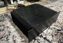
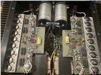
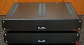
Last year my dad convinced me to get the KEF 107/2 (came with the proper kube too). He also found the exact same Krell KST-100 he once had (which I vividly remember from my childhood).

I am hitting 40 soon while my dad has been at this for 40 years; designing and modifying his own audio equipment, all of which I vividly remember since I was 5.

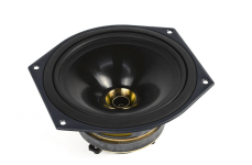
So after purchasing both, he recapped the KEF 107/2 for me (except the hard to find 240uf caps but they were fine), reformed them, redid the woofer cones and refilled the ferrofluid.

I finally brought them into my home in the new year and started listening to them
  1. Minipc for the source (Tidal)
  2. Portable phone DAC (cheap $100 USB powered from amazon)
  3. Some cheap bias knob pass through for volume control ($30-$40 on amazon), 4.4mm balanced <> RCA connecting to the DAC and RCA to the amp
The sound was muddy, not enough bass, not clear, I used FX Sound (free windows EQ software), it helped, but it was still 'not right'.

I spent hours playing with speaker position and tweeter direction. In the end the best sound in my space was bringing them as close as possible (KEF recommends 2.4m, mine are wider), over 1/2 meter away from wall and titled/toed in entirely, with tweeters directed towards me so I get a triangle seating position. This was the best I could pull off.

No amount of EQing could get the soundstage or sound to improve further from this, so I kept researching DACs for months, all pricey or bad reviews. Long story short, I got sold on the SMSL SU-1 as an entry united but it was going to take a month to come, SMSL C-100 was here next day (I went through a lot of youtube reviews). Yes I am aware of R2R DACS, even the Gustarted R26, SMSL's R2R DAC, so many other 2k+ options. Even mid-range SU-10, SU-9 Ultra, D400EX, so many options but I ended up going with this, cheap and next day shipping.

Boy... did it wake up the setup, the portable DAC was GARBAGE (obviously), no need for EQ adjustments. It also had 6 filters, kinda useless, except 2nd option was 'warm' and I liked that. Boy big change, but still not 'right'.

Next, I figured, let me get better cables. What I had in place was plain copper wires, chopped at both ends and 'tugged in', with the biwire option also 'tugged htrough' with the plastic sleeves chopped so it passes through the posts.

First thing I got was new cables, banana to spade. Boy it made a difference, I listened to two days and it was nice once broken in, an improvement in sound stage. Right away next I ordered spade to banana bi-wire jumper cables, once again an improvement compared to the chopped copper cables that I used as jumpers.

Then I ordered some RCA cables and connected the Kube, boy, do NOT listen without a Kube, the sound was smoother and more controlled. I played around with the LF and HF knobs and I could hear a difference, initially I increased the LF to the max for impact, but it dulled and caused bass to be boomy.

It still didn't sound 'right'... so I kept reading and realized wait, I have 4 posts on my Krell, so I looked around for better cables and got Full copper oxygen free cables with gold plated bananas on both ends. Connected to the MF/HF posts straight from the amp, it sounded 'warmer and smoother'. Then I did the same with the bass and it sounded 'dull'.

So I was confused, but then I read reviews on these cables (Micca on amazon) and everyone raved about them, so I figured, I am too hasty, give them time to break in, so I listend to the 2.5 days straight and they improved but something was still 'off'.

Tonight my parents came over and while listening he told me to turn down the LF on the kube and set it to the neutral base position, I did and while the image was cleaner it didn't have the impact or oomph and I hated that. It all still sounded dull.

Well yesterday I ordered legs for the speaker spikes to sit into (they come with spikes which a lot of people don't know, the bottom plastics come off). Well I got the nickel plated ones (cheap order from amazon) and installed it with my dad.

HOLY crap, who would think LEGS make this much a difference. Instantly EVERYTHING sounded better I **** you not. Bass was clean, impactful, not boomy. So much details started showing up in the sound image, airy details of instruments, voices, strings, INCREDIBLE.

Since they left, I've been relistening some of my testing music and I am so impressed. They sound PROPER now...

So when people say small details are placebo, no they are not, cables, position of speakers, these spikes preventing resonance and boominess, better control, it all came together.

One last thing is arriving tomorrow, ordered CARDAS XLR jumpers for grounding (as they didn't come with the sale of the KRELL amp). I hear light noise on the right speaker tweeter, my dad told me to get this, so that's next.


That's my update, I love the setup, it is so harmonious, clean, smooth, warm, clear, detailed and impactful, you can hear the air moving, the depth of the stage, which was all missing when a bad dac was in place, bad cables and no proper feet on the KEFs (the plastic was driving everything into the floor).

Anyways for the future plans a better DAC, monoblock aleph amps and perhaps custom enclosures like what my dad once built are all down the line, but tonight everything came so nicely into place. I am blown away how the removal of the plastic bottoms altered the quality of the sound so much. I got goosebumps, it was so satisfying.
  • Like
Reactions: wchang

Patio Sub

Hello,

I thought it would be an interesting project to see if I could make a smaller subwoofer to move to the patio for a little extra bass in the summer.

Criteria
1. Portable - keep the size and weight down. 1.0 to 1.25 cuft
2. Not looking for low bass, but rather a punchy midbass to fill where the outdoor speakers leave off.
3. Efficient'ish -- I have a 500watt sub app for the project to reuse.
4. 10" or 12" drive max
5. I am using a WiiM Pro as the source and it has a parametric EQ so I have decent control for some fine tuning.

First driver that caught my eye was the Dayton Audio - RSS3315HO-4 (not the -44). I fired up WinISD and with a 30 Hz tuning things looks ok. For comparison sake, I thought I would try a couple other drivers. The UM12-22 (thinking it should not be ideal in a small vented box) and the MX12-22 (also likely not idea). As I thought, the MX needed a larger enclosure so I rejected that option. Here is the strange part, the UM12-22 seemed to model better in every way than the RSS315HO-4. What really didn't make sense to me was the output (set at 300W in WinISD) was that the UM12-22 had more output but is significantly less efficient?!?!?! I double checked the T/S parameters in WinISD -- looked ok. The other thing that didn't make sense is that the vent length was identical for both (1"x12" slot 25.77" long). That's a long vent but I think I can make it work.

Questions
1. Did I make a mistake some place and my model is wrong?
2. Any other reasonably priced drivers I should consider? SB Audio ones seemed to require larger boxes

Thoughts or comments welcome

Cheers!

Attachments

  • air-velo.png
    air-velo.png
    11.4 KB · Views: 59
  • freq-plot.png
    freq-plot.png
    11.9 KB · Views: 68

myryad MA500

Hi guys,

does anyone know if there is a service manual available somewhere for the Myryad MA500?
I want to recap mine (23+ years old and it runs a bit warm). During dismantling I discovered that no bleed resistors are built in: the psu pcb shifted a bit and the filter caps discharged unplanned and uncontrolled on it's own mounting bracket. Optically, there's no damage other than a black spot on the pcb. But I can't test the unit at the moment. During the recap, I might as well replace any and all components around the fried spot on the pcb. Including some diodes I know nothing about, except a voltage rating of 22V (D609, D610). So a service manual might come in handy to identify risk-areas and components.

Thanks in advance!

James.

Help with Hickok 539C!

HELP WITH HICKOK 539C!
Hello everyone, I am writing with the hope that someone with more experience in the repair and calibration of this equipment can help me, I am calibrating the Hickok 539C and so far everything is going well except that when I set the function switch to H the fuse lights up brightly. , I only found this when it is set to H, I don't know if this is normal or there is some problem (short) in this switch, any help will be greatly appreciated.
greetings
Alex
20240520_095039[1].jpg

For Sale Pioneer PA0016 chip x2

Selling 2 new genuine Pioneer PA0016 chips still in their original bags(never used) purchased years ago from Pioneer distributor .
I had a Pioneer A-717 amplifier that i never repaired .

These can be very useful for someone repairing Pioneer 7-series amplifiers as these chips are obsolete and really hard to find .
Asking 50€ for both + shipping.

Thanks

Attachments

  • pa0016.jpg
    pa0016.jpg
    239.3 KB · Views: 153

SEAS KingRO4Y Mk III Active Loudspeaker Kit - as an OB?

SEAS KingRO4Y Mk III Active Loudspeaker Kit - as an OB?

Hi,
I was looking at the Madisound kits and was curious if you could do the KingRO4y as an Open Baffle speaker.

I seem to recall reading somewhere that for an OB, you want drivers with a QTS greater than .6?
Thought I could do one w the plate amp in the base?

With the 10" driver ... how wide would the baffle have to be?

This was just a thought that crossed my mind. More of a thought exercise than actual project.

Thx

Advanced loudspeaker and room correction using REW and RePhase

Hi!

I found this tutorial on how to use REW and RePhase to do both EQ and Phase correction
Login to view embedded media
Hands down the most interesting and new way I have ever seen so far. Maybe not for beginners... but if you follow the steps maybe you can make it too.
I will try...

PreAmp tube upgrades

I have a tube preamplifier for my turntable that has no markings so I don't know anything. I also am extremely new to the use of tubes but want to upgrade the tubes in the preamp to potentially get a fuller and cleaner sound. The preamp has 2 of 819 6Z4 tubes. 4 of 6N2-J tubes and 2 of 12AX78 tubes. They all appear to be Chinese made and the preamp has a tag that is in either Japanese or Chinese. Can anyone help me find upgraded tubes?

Zu Audio "Tone" full range driver T/S parameters

Hi All,

I have a pair of Zu audio Tone bookshelf speakers (I believe there were also called Omen bookshelf) and I would like to build a little larger cabinets to "squeeze" lower bass from them.
On the back panel there is "2010" so I believe it's the speakers production year, as far as I know there were few revisions for these speakers and there was a change in the full range driver at some point, from Zu260FRD/G4 to Zu260FRD/ND.
There was also a change in the super tweeter and in my speakers it looks like the newer model.
Does anyone knows which full range element has been used at 2010? And were I can find the driver's thiell small parameters?

Thanks

Goldmund clone boards, which would you choose and why?

Dear knowledgeable folks of DiyAudio, I want to build a Goldmund clone amp, and come across these following boards. Which would you choose and why? Does anybody know on what Goldmund amps these boards are based? Any experiences with these boards and tips on the build are very welcome too.
Extra boards and extra info will be added in follow up posts.

Board 1: 200W Mono Power Amp Board based on Goldmund Line + PSU Board L11-30, 2SC2922/A1216

As far as I can tell this mono channel board comes with a powersupply board with speaker protection and rectification and 4x 10.000uF 63v Rubicon capacitors. The voltage rating on the caps seems too low to me to make this into a powerfull 200watt amp (I think it needs like 70v DC to be a 200watt amp, please correct me when I am wrong).

Any experiences or thoughts about this board and the psu board?

Gzlozone-Assembeld-200W-Mono-Power-Amp-Board-Base-on-Goldmund-Line-PSU-Board-L11-30.jpg


Gzlozone-Assembeld-200W-Mono-Power-Amp-Board-Base-on-Goldmund-Line-PSU-Board-L11-30.jpg


Gzlozone-Assembeld-200W-Mono-Power-Amp-Board-Base-on-Goldmund-Line-PSU-Board-L11-30.jpg


Gzlozone-Assembeld-200W-Mono-Power-Amp-Board-Base-on-Goldmund-Line-PSU-Board-L11-30.jpg


Gzlozone-Assembeld-200W-Mono-Power-Amp-Board-Base-on-Goldmund-Line-PSU-Board-L11-30.jpg


Gzlozone-Assembeld-200W-Mono-Power-Amp-Board-Base-on-Goldmund-Line-PSU-Board-L11-30.jpg

Project FAST/WAW compact open baffle : Lavoce LBASS15-15-8 and MarkAudio Alpair 5.3 / MAOP 5

Hello,
A new fast fun inexpensive OB project. It is my second attempt to do a FAST OB. Several reasons to this defect but not suitable drivers.

Looking for a woofer usable for OB, I found this one, a driver for bass guitar : Lavoce LBASS15-15-8
Some challengers were simulated Fs < 40Hz Qt > 0.6 Not a lot of contenders.
  • SB Audience 15OB350 design for open baffle, has the best max output level. My second choice because the Lavoce has a lighter cone and less expensive, less crossover cost.
  • Celestion Pulse XL 15 Interesting but too much crossover work to have the same bass extension as the others.
  • Eminence Alpha 15 Best bass response 40Hz less sensitivity 85dB and a peak in the group delay. The most expensive in the group 200€ ! Harder to find in Europe

The choice for the mid-tweeter : I saw a lot of tests and based on return of experience on the web : Markaudio seems to be the way to go. There are also Fostex FF85WK.
I want a good treble as good as dome tweeters. Many fullrange i listened to has not the treble I want it very realistic. And the mid is couloured... It is my opinion 😉.
For the mid_tweeter I tried first an Alpair 7ms, good mid but treble miss extension to my ears. Go to Alpair 5.3 the sound became ok to my ears.
I tried first a 6dB crossover, LR2 slope but the sound was sometimes muddy in the midrange. Go to LR4 slope, all things are OK.
I wanted to test the MAOP 5, my opinion it is a more refined and neutral driver than Alpair 5.3 . The two drivers have the same response on the baffle.
This design should work with FF85WK or Alpair 7ms, not tested with a LR4. The crossover is a little different, 8 ohms drivers.
It is not a very expensive speaker 500-600€/$ for a very good sound.

The bandwidth is 50Hz-20kHz 87db/2,83V . The Qt of the woofer on the panel is 0.8 and 36Hz resonance. I made some measurements, the response curve of the speaker is honest. The crossover frequency is 640Hz.
I was a little lazy for the construction, the panel is a shelf board with standard dimension 80cmx40cm.
It is a compact open baffle. I add a shelf bracket in the back to tilt the panel.

There are some similar old projects :
John Busch (RIP) Fast, fun, Inexpensive OB project
Martin J. King MV Model 3P OB Loudspeaker Project

I enjoy a lot the speaker, it works good to my ears.

Have fun.

photo_lbass15_maop5-jpg.1311300

Attachments

  • Diagramme_lbass_guitare.schema.png
    Diagramme_lbass_guitare.schema.png
    22.2 KB · Views: 308
  • FAST_OB_Bass_Guitar XO-schema-1.png
    FAST_OB_Bass_Guitar XO-schema-1.png
    7.9 KB · Views: 2,236
  • photo_lbass15_maop5.jpg
    photo_lbass15_maop5.jpg
    301.9 KB · Views: 3,439
  • Measured_response.png
    Measured_response.png
    15.7 KB · Views: 252
Projects by fanatics, for fanatics
Get answers and advice for everyone wanting to learn the art of audio.
Join the Community
507,714
Members
7,885,588
Messages

Filter

Forum Statistics

Threads
406,105
Messages
7,885,588
Members
507,714
Latest member
sjun1019