Please simulate multiple drivers in a waveguide

Hi,

There are lots of small drivers and I want to put them in a waveguide and see the polar response.
The drivers I am talking about are these, probably used in mobile phones.

https://www.farnell.com/datasheets/4197292.pdf
https://www.farnell.com/datasheets/4197300.pdf
https://www.farnell.com/datasheets/3999554.pdf

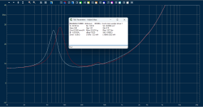
I have seen better round ones available locally and measured them to be much flat than above ones and Fs of 750Hz.
If a mobile can make sufficient noise then these should be able to act like a nice tweeter when several are put in a waveguide.

Please note Don Keele used used 48 AKG XXL‐V5 Headphone Drivers in one and Toshiba laptop drivers in another and Harman multimedia driver in his CBT prototypes.
https://www.linkwitzlab.com/Keele - Introduction to CBT Loudspeaker Arrays.pdf

Before I get to the actual dirty work with 3D printing the entire thing, can somebody help me please simulate them?
I would appreciate if someone could simulate 15mm sound sources put on a spherical cap in an 8 inch 90 degrees conical waveguide with good round over leading to the baffle.

The following scenarios could help understand whether the idea has merits
a) 7 sources ie one in center and 6 surrounding in a circle, concentric arrangement on spherical cap, the spherical section should perpendicularly mate with the wall of the waveguide, all driven by same signal.
b) Same 7 sources in concentric arrangement on spherical cap, the side ring shaded by -3db than the center one. To get 90 degrees wave front the spherical cap should 138 degrees as per CBT theory.
c) 19 sources ie one in center and 6 surrounding in a circle, and another 12 in a surrounding circle concentric arrangement on spherical cap, the spherical section should perpendicularly, all driven by same signal.
d) Same 19 sources in concentric arrangement on spherical cap, center one at full strength, the next circle of 6 at -3 dB and the outermost circle of 12 at -6dB. To get 90 degrees wave front the spherical cap should 138 degrees as per CBT theory.

The b) and d) are essentially small spherical CBTs in a waveguide and a) and c) are unshaded curved drivers in a waveguide.

1749894899897.png


Few more driver in Don's presentation
1749895612709.png


I will attempt a 3D printed version of whichever gives good polars and post here the measurements.

Thanks and Regards,
WonderfulAudio

Cap Replacement Question

Folks:

I'd like to replace the capacitors in my 17-year old Audio Electronic Supply AE-25 SuperAmp Signature. Selecting upgraded caps will be easy for the most part, but I'm unfamiliar with the five purple "Audio 1" 0.22uF, 600VDC capacitors shown in the photo. I have very limited experience with tube components and would be grateful for advice on a suitable replacement for those purple caps.

And before anyone points this out, yes, there's a 560uF 400V cap that's already been pulled from the lower left corner of the chassis.

Regards,
Scott

Attachments

  • tempImagekqgeh9.gif
    tempImagekqgeh9.gif
    1.7 MB · Views: 108

Simple High Performance DC Coupled Class A HPA with sub PPM THD

Edit April 5, 2019: Beautiful example of this amp in finished case by Avtech23 on post 425.
747613d1554435767-simple-performance-dc-coupled-class-hpa-sub-ppm-thd-sherpafinished1_dxofpr-jpg


747614d1554435767-simple-performance-dc-coupled-class-hpa-sub-ppm-thd-sherpafinished2_dxofpr-jpg


*****

This is a simple DC-coupled high performance SE Class A headphone amplifier design by member TimS who has approved this GB. The design uses four cascoded BF862 JFETs on the input stage. They provide compensation for DC drift and the amp has stable DC offset of less than 5mV. The design has a dynamic CCS, reminiscent of an Aleph to provide good efficiency and low distortion from two P-channel MOSFETs in the output stage. Simulations show very low THD in the sub 1 part per million (PPM) range for 5vpp into 55ohms for a 400mA bias current. At this bias, the heat output is about 14w per channel and allows it to be used as fleawatt speaker amp and able to drive 8ohm speakers to 1.5w with 0.004% THD. Increasing the main source/drain resistors to 2.7ohms sets the bias current at about 115mA and this has very good performance. I built a hand etched prototype and measurements and listening shows a very powerful, dynamic, and clean sounding amplifier. The GB boards will be high quality 1.6mm thick with 1oz copper and ENIG gold finish with blue solder mask.

Here is LTSpice schematic and DC setpoints for simulation:
685372d1528348988-simple-performance-dc-coupled-class-hpa-sub-ppm-thd-tims-simuation-schematic-v3-png


Predicted FFT for 5vpp into 55ohms with 400mA bias:
685377d1528349430-simple-performance-dc-coupled-class-hpa-sub-ppm-thd-tims-simuation-400ma-5vpp-42ohms-fft-png

Here is hand etched prototype:
685071d1528188075-simple-performing-headphone-amp-img_1820-jpg


Measured FFT for 115mA bias 1vpp into 42ohms - note that elevated H2 distortion peak is probably a component choice of the lwo cost prototype (cheap steel leads on resistor, etc). I am quite sure that a proper amp using a real PCB and all high quality resistors and MOSFETs will be superior:
685361d1528330028-simple-performing-headphone-amp-tims-simple-hpa-1-0vpp-42ohms-fft-png


Measured 1kHz sine wave at 17.6vpp for 115mA bias and +/-15v rails for almost 1wrms into 42ohm load
685358d1528329940-simple-performing-headphone-amp-tims-prototype-test-1khz-sine-clip-jpg


10kHz 2.5vpp square wave - nearly perfect performance with no overshoot, or ringing:
685359d1528329940-simple-performing-headphone-amp-tims-prototype-test-10khz-sq-wave-jpg


This is the schematic for production PCB:
685373d1528348988-simple-performance-dc-coupled-class-hpa-sub-ppm-thd-timss-final-schematic-prod-png


Here is the layout by JPS64:
684977d1528123994-simple-performing-headphone-amp-5b1e1d98-a607-4bd7-bf35-7935a0f78e8d-jpg


Here is 3d render of PCB with components (bottom side):
684975d1528123994-simple-performing-headphone-amp-c96ec7c8-2f08-47ac-9ea1-90d82ccd56d6-jpeg


3d render of PCB with components (top side):
684976d1528123994-simple-performing-headphone-amp-fbedc091-3dcd-42a5-8ec0-2aafb59eb563-jpeg


How does it sound? Very dynamic, transparent, open with deep deep bass. It is DC coupled in and out so there is no capacitor to color the sound. The distortion is very low and you have to be careful not to play your headphones too loud if you are used to judging loudness by distortion. It's a great little amp that is easy to build with relatively low cost parts, yet is very high performing. Compare the predicted distortion levels with amps using 5x as many transistors. The nice feature about this amp is the rather high output power it is capable of and a rather high gain close to 20dB that allows one to drive an inefficient set of planar magnetic headphones to loud+ levels with very low distortion.

If there is interest, please add your name to GB interest list. Cost will be about $28/set and shipping will be $5 in US, $10 in Canada, $15 everywhere else.

Update July 3, 2018;

The FFT of the wall mains powered 12v to the on-board ultra low noise DC-DC dual rail PSU has noise characteristics resembling a battery. Note total absence of 60Hz/120Hz/180Hz/240Hz mains peaks and how low the "grass" of the noise floor is:
688827d1529986528-simple-performance-dc-coupled-class-hpa-sub-ppm-thd-tims-hps-dc-dc-psu-142ma-1-02vpp-47r-fft-2-png


Here is the final design for production, and it is an 8 panel board that contains:

  • input and source switch board (only preamplifier version)
  • crossfeed board (with defeat Xfeed ON/OFF switch)
  • headphone jack output board (6.35mm stere TRS output jack)
  • volume potentiometer board (with the possibility of three different types of pots)
  • PSU (includes CLC, DC-DC dual rail step up, cap Mx, CRCRC filter to produce battery-like rails from simple 12v wall-wart)
  • CLC filter board (in case you want to use your own PSU)
  • ON/OFF switch board
  • amplifier board

The above boards can be mixed and matched and connected for either an HPA or a preamp following this diagram:
689951d1530589553-simple-performance-dc-coupled-class-hpa-sub-ppm-thd-simple-hpa-block-diagram-png


Schematics and other data here:
Simple High Performance DC Coupled Class A HPA with sub PPM THD - Page 10 - diyAudio

Top side:
689952d1530589553-simple-performance-dc-coupled-class-hpa-sub-ppm-thd-shpa-pba-top-2-jpg


Other side:
689953d1530589553-simple-performance-dc-coupled-class-hpa-sub-ppm-thd-shpa-pba-bot-2-jpg


Mounted in a popular all CNC'd $36 Aliexpress case as a HPA, it looks like this:
689422d1530307921-simple-performance-dc-coupled-class-hpa-sub-ppm-thd-hpa_front_2-png


Here is rear view of HPA:
689423d1530307921-simple-performance-dc-coupled-class-hpa-sub-ppm-thd-hpa_rear_closed_2-png


As a preamp with your own machined panels, it looks like this:
689375d1530286481-simple-performance-dc-coupled-class-hpa-sub-ppm-thd-tims-preamp_open-jpg


Rear view of preamp:
689374d1530286481-simple-performance-dc-coupled-class-hpa-sub-ppm-thd-tims-preamp_rear-png


Edit July 21, 2018: final schematics and stuffing guide here:

Simple High Performance DC Coupled Class A HPA with sub PPM THD - Page 10 - diyAudio

Update Aug. 4, 2018: Schematic Update! Please use this schematic for the PSU as the original has a few typos.

Update Aug. 5, 2018: Silkscreen on PSU PCB has error: Diode V241 has cathode and anode flipped.. Mount diode with Anode towards Drain of P channel MOSFET on cap Mx.

Update Aug. 27, 2018: verification build of GB boards completed. Amp sounds superb and measures very well. Here is FFT for 1vpp into 51ohms - very similar to earlier measurement but much lower distortion.
699591d1535270403-simple-performance-dc-coupled-class-hpa-sub-ppm-thd-shpa-gb-build-01-jpg


699790d1535317831-simple-performance-dc-coupled-class-hpa-sub-ppm-thd-shpa-gb-verif-build-fft-1-03vpp-51ohms-png


Update Sept 2, 2018: BOM from verification build can be found here.
Simple High Performance DC Coupled Class A HPA with sub PPM THD - Page 24 - diyAudio

Attachments

  • TimS-Simuation-Schematic-v3.png
    TimS-Simuation-Schematic-v3.png
    53.4 KB · Views: 6,852
  • TimsS-Final-Schematic-for-Prod.png
    TimsS-Final-Schematic-for-Prod.png
    97.4 KB · Views: 7,501
  • TimS-Simuation-400mA-5vpp-42ohms-FFT.png
    TimS-Simuation-400mA-5vpp-42ohms-FFT.png
    9.4 KB · Views: 5,808

Transient Voltage Suppressor (TRANSZORB®, TVS) vs. Zener Diode - which Differences in Protection on 5V Modules

basic information concerning the differences are described in detail here:
http://www.reallyreallyrandom.com/www/Zener_Theory_and_Design.pdf
and here:
https://www.onsemi.com/pub/collateral/hbd854-d.pdf

AI short form description as follow:
a TVS (Transient Voltage Suppressor) diode is used as an alternative to a Zener diode, particularly for dropping screen grid voltage in tube amplifiers. While Zener diodes clamp the voltage to a specific level, TVS diodes act more like a protector, absorbing over-voltage transients and shielding other components.

But I wonder, why such TVS diodes (TRANSZORB®) "SMAJ-5.0A" - for datasheet go to
https://www.vishay.com/docs/88390/smaj50a.pdf
very often causes a total failure of various components with 5V plug-in power supplies (because this TVS diode has an internal short circuit after a short time of use - i.e. works like a wire bridge between the plus rail and the minus rail).
In the moment I have 3 devices of this kind of electronic modules without any operating:
https://www.revitive.com
After looking for the most probably reason therefore I have found this video examples on youtube:
Revitive Circulation Booster | Won't turn on | Can I Fix It? (10:33)
Revitive Machine No Power Repair (5:35)
Faulty REVITIVE Circulation Booster | Can I FIX It? (3.15)
Always the shorting inside of the TRANSZORB® TVS diode "SMAJ-5.0A" was the reason - but the reason therefore again wasn't the 5V SMPS power supply.

I remember many previous repairs on other kind of assemblies that were operated with 5VDC, the total failure of which was also due to a short circuit of such TVS diodes. In these cases I always replaced it with a high power 5V1 Zener diode and additionally with a normal fast recovery diode BY299 to trim any transients in reverse polarity that may
occur - fortunately without any trouble with further use.

But what actually is the royal step to get on one hand optimal protection requirement and OTOH best reliability for the protection part itself (obviously TVS diodes like the SMAJ-5.0A isn't reliable)?

Thanks for an advice.

Hello

Hey all. Alex here. I live in New Orleans. I'm getting into HiFi and DIY HiFi.

My current setup is:
Fluance RT82 upgaded to OM20 stylus with acrylic platter
Schiit Mani 2 Phono Pre-amp
Schiit Freya+F Pre-Amp with 6SN7 Tung-Sol tubes
Schiit Vidar 2+F Power Amp
Cambridge Audio AXR100 (when not using the Freya+Vidar)
Eversolo DMP-A5 Gen 2 Streamer
Laiv Harmony uDAC
Cambridge Audio AXC35 CD Player
Wharfedale Evo 4.3 Speakers
Cambridge Audio Minx X201 subwoofer

Custom Cables: Various RCA cables with Deulund Silver 26ga wire and Gotham Cable with low mass connectors, speaker wires and XLR cables with mogami wire and neutrix connectors.

I've joined the forum for a few reasons. I've been building an IanCanada transport to hook up to the Laiv Harmony uDAC. I need some troubleshooting help getting the IsolationPi III working with the TransportPi Digi/II and RoPieee (I'll post details for that somewhere else), and I'm also looking for CNC custom enclosures, or putting together some people to find someone to make files where we can order one. I'm also interested in building the Amp Camp Amp Redux Kit. I've also been building all my own custom cables, so interested in speaker cable stuff. I'm also thinking long term building my own class A mono block amps.

Glad to be here. I've been reading the forums and lots of great stuff to see.

Effect of damping on the back of a woofer

Few weeks ago I encountered a Sonab speaker (I think it was a OA5) fitted with a Philips M9710 driver, the back of the driver covered with a basked lined with damping material.

1749272921899.jpeg
1749272942688.jpeg


1749272971954.jpeg
Photos from Troels Gravensen website here.

Troels descibes the purpose of this construction.
the 9710 driver placed in a metal mesh basket with some heavy glassfiber material between driver and mesh, making a low-pass filter that can be adjusted due to the basket being suspended on three screws that allows you to increase or decrease the acoustic resistance of the fiber material. An acoustic vent, sort of. Something similar can be found on some Lowther drivers.
I remember having seen similar constructions in fifties and sixties radio's. Seeing it again made me curious, so I did a small experiment using a pair of mini 3 inch woofers (originally from a pair of Peaq PC speakers). I measured the TS parameters, shown right.

IMG20250527163708.jpg
3 inch mini woofer 1 TS param.png


To keep it simple I just covered the back of the driver with gaffa tape.
IMG20250527170100.jpg
IMG20250527170050.jpg


And measured again the TS parameters and impedance. Red is driver impedance, White driver impedance with added mass (7 gram)

3 inch mini woofer driver 1 - with masking tape TS param + impedance.png


3 inch mini woofer driver 1 - with gaffa tape TS param.png


Effects:

ParameterNo dampingWith damping
Fs91,583,5
Qms4,183,11
Qes1,00,87
Qts0,720,76
Cms0,3830,333
Rms1,091,84
Bl6,246,55
dBspl81,479,0
Vas0,990,86
Mms7,910,9

I repeated the experiment with masking tape instead of gaffa tape. The result was essentially the same. To illustrate the effect of these changes I simulated a closed box with Basta:

3 inch mini woofer driver 1 - Basta sim CB 2ltr GHP 1200uF.png

Box 2ltr
GHP C=1200uF
Viso=80%
Qb=20

driver no tape Fs (-3dB) = 103Hz, Eff 81,2dB
driver with tape Fs (-3dB0 = 80Hz, Eff. 80,3dB

So for a loss in efficiency of about 1dB we can lower the Fc of the speaker from 103Hz --> 80Hz. The effect seems to be caused by the added mass due to the air enclosed between the cone and tape, and the added resistance to the air moving.

The method used by Sonab seems to be a way to control the effect.

Attachments

  • 3 inch mini woofer driver 1 - with gaffa tape TS param + impedance.png
    3 inch mini woofer driver 1 - with gaffa tape TS param + impedance.png
    171.5 KB · Views: 83
  • Like
Reactions: Booger weldz

Purifi EVAL1 Ghent case build instruction

Hi, this is my first post on this forum. I have however been here many times reading a lot about how to build my nCore mono amplifiers a few years back and also on how to build a stereo Purifi EVAL1 amplifier very recently.

However, I was not able to find a clear step-by-step instruction on how to build a stereo Purifi EVAL1 amp. So I created an instruction myself. I figured it would be nice to share it here as many like me would try to find such an instruction here.

I used the Ghent Audio stereo Purifi case kit, Ghent Audio harness, Hypex SMPS1200A400 and the Purifi EVAL1 module.

Hopefully you like my step-by-step guide. If you have suggestions or find errors, please let me know. Thanks!

Link: iCloud

BR,
Richard

introduction

Im new to the forum. Recently I retired from the Voice of America. I worked on high power shortwave transmitters. Ive been in broadcasting over 40 years. My audio interest are horn systems which I have just gotten into. I recently finished a set of EV eliminators modified to be a 4 way system great party speakers. I hope to learn n much here Hve a great summer everyone!

Peavey FH-1s

I just picked up a pair, also got the tops. Used to have the SP1 variant of these years ago.

I’ve seen some posts from people stating the Klipsch 33, 43 or the Emminence 15c is the way to go in these bins.

I’m using these in my workshop with the occasional yard parties with a pair of Dynaco Mark 3’s.

Does anyone have any experience with these and can recommend a driver for them as well as a complimenting horn driver(s) for a passive 2 or 3 way setup?

9A1A28C1-ABFF-4F0D-9E6E-6ABC055BAC04.jpeg
  • Like
Reactions: indianajo

Greetings from Germany – Speaker Builder Turning Horny

Hi everyone,

My name is Friedrich, I’m from Germany, and I’ve been into DIY audio for quite a while now. Over the years, I’ve built a variety of speakers — sealed, ported, transmission lines — and a few amplifiers as well, including some SymAsyms. I’m currently working on my take on the Aleph P 1.7 preamp.

Now it’s time for something new: horn speakers. My first project in this area will be a clone of the Avantgarde Acoustic Zero XD, a speaker that’s inspired me for a long time. I'm really looking forward to the challenges ahead and learning from the collective wisdom of this community.

Glad to be here and excited to connect!

– Friedrich

How can I get 20-25Hz boost?

My system lacks deep bass response—below approximately 65Hz—while the speakers have dual 10” woofers per cabinet; Braun LS200. The amplifier is an integrated amplifier Braun atelier A2. I normally don’t use Loudness button and tone controls (both bass and treble knobs).

In fact, the Braun LS200 were launched with their own amplifiers which would be attached to the recess at the back of the cabinets modeled Braun PA1. The PA1 literally has a deep bass adjustment knob which allows user to boost or cut deep bass output by +/-3dB. The deep bass is referred to 25Hz frequency according to the user manual. Nevertheless, there’s an alternative choice for amplifying these speakers. It’s a separated component launched for them as well which are Braun CC4 and PA4, preamplifier and power amplifier, respectively. The CC4 also has deep bass boost adjustment where deep bass is referred to 20Hz and level is 0-6dB range.

As you can see, it’s likely that the LS200 speakers were designed to have deep bass assistance by electronic. And, I couldn’t agree more with this idea. As mentioned earlier, I use an integrated amplifier, A2, with linear mode operation—never use Loudness and tone controls.

I’d like to ask how can I get deep bass assistance with the lowest cost, except using anything cosmetics the signal such as Loudness, EQ, and Tone Controls?

Actually, I also have the answer in my mind that is using a subwoofer. However, the question was initiated because my subwoofer is now being repaired, Lol. And I thought I already have four 10” bass drivers in my hands, so is there any way to maximize outcomes from them?

I would love to hear everyone’s thoughts.
  • Like
Reactions: NBPK402

Isolating a mains-connected regulator

Hello friends.


I have this zener follower regulator below and its input is 120 VAC; here in Canada that's the mains voltage. Although I do have a suitable transformer for it, for space and weight considerations it would be nice if I could dispense with it and hook up directly to the mains (ceramic fuse protected). I believe the correct term for such a connection is "in-line" ?.

Capture d’écran 2025-06-12 190216.png


Of course in that case the circuit ground above would not be tied to mains earth as that would shunt a diode at each half cycle, neutral and earth being tied at the distribution panel. This circuit feeds an ultrasonic vacuum tube heater supply that has an output transformer; so the business end will be isolated and grounded.

For safety and also EMI reduction, the whole contraption would be put in a grounded metallic case, which in turn would sit in the main amp enclosure, also earthed - Implementing class II double isolation. Not shown on schematic, discharge resistors across the caps both upstream and downstream of the pass mosfet would be placed for added safety.

So.............. What can go wrong right ?
As always, thanks in advance for any insights.

Joris

GR Research "The Bully" with built-in active servo subs

I am considering this kit as an all-in-one solution to the problem of in-room bass response for a full range speaker (HiFi use only). I suspect it could give me Vandersteen-tier performance.

I like that you don't need to have two subs scattered around the room, or an in-line filter or DSP. Plus the 94dB sensitivity means I can use a cheaper amp.

Does anyone know of any pitfalls going down this path? GR Research's kits and speakers are highly rated and the designer seems to know what he is talking about.

https://gr-research.com/product/old..._subwoofer-jumper-set=Include+$75&zCountry=AU. (scroll for videos)

review:
Login to view embedded media

Is ADAU1701 good enough for real speakers?

Hi,

There are many boards from Tinysine that use I2S input to ADAU1701 and then use the inbuilt DACs of the chip. It is comforting that the ADCs are not used and one can feed I2S from Toslink, Coaxial, bluetooth, and of course one could take HDMI ARC converter and feed Toslink to these amp boards from TV too.

The board I have in mind is this https://www.tinysineaudio.com/products/tsa1702c-spdif-coaxial-dsp-audio-receiver-board

Does the DAC quality matter on real speakers?
My speakers are https://jblpro.com/en/products/jbl-nano-k8
And I am building 12 inch stereo subs using TPA3255 for a 2.2 system.

The reason why I ask this question is I have a feeling that one could make out the deficiency of the ADAU170 DACs using headphone based listening but probably not speakers.

Warm Regards,
WonderfuAudio

Nemesis NA-6KM output Mosfet identification?

Hi everyone,
I bought this Nemesis as is and the output Mosfets were annihilated. All 10 were destroyed. On the botton side there was 5 IRF3205'and naturally I assumed that the top would be the same. After further troubleshooting I noticed that they were not all the same. The top side had only two as pictured, PLUS a MUR2020CT and 2 goofy ones marked 01A. I feel like that is incorrect. Any inputs you guys are really appreciated.
Preview attachment IMG_2569.jpg
https://mail.google.com/mail/u/0?ui...attid=006C07E4-A75D-4FBE-9EAA-7B3B41B2B92F&zw


Preview attachment IMG_2570.jpg


Preview attachment IMG_2571.jpg


IMG_2571.jpg
4.7 MB

icon_1_image_x16.png

Preview attachment IMG_2573.jpg


IMG_2573.jpg
5.4 MB

Preview attachment IMG_2572.jpg


IMG_2572.jpg
4.8 MB

IMG_2570.jpg
4.5 MB

IMG_2569.jpg
3.6 MB

Audio Research D70 MKII

Some might call me a glutton for punishment, but I have taken on one of these that’s sickly and that has even had modification attempts! I’m nearly at the point of digging into the power supply. It’s great to have schematics available online, but I’m struggling with identifying ZD12. It‘s labelled as a ZD20, but I’m clueless at exactly what that specific Zener is. Would anyone know?

MEH 2 way + sub vs 3 way

I currently am running a pair of k402MEHs as a 3 way with a pair of f20 subs. I just picked up a Yamaha sp2060 and it offers a 2 way + sub configuration and a 3 way configuration. I like having the full range for my stereo setup (my MEHs will dom20hz to 20k, but I am pushing the M3H 15"Celestion woofers too hard..hence using as a 3 way now).
What is the difference, and what would the advantages and disadvantages be. I am using a Denafrips Athena 2 channel preamp for my stereo setup and feed my Marantz av8805a into one input on the Athena for movies.

Introducing AST Conductors

I would like to introduce AST Conductors, a new company in the market, but with
a history of several years of advanced R&D. We have been passionate
audiophiles and DIYers forever and we also happen to include in our team accomplished
metallurgists with connections to the research community.
For several years we were discussing ways to develop the best possible silver
conductor, as there were products in the market which indicated that there is some
upside there,
Having rewired several amps and other equipment (both DIY or not) we knew very well
the importance of the hookup wire quality and, of course, the material used in cables.
So we embarked on this R&D journey and invested in some pretty high-tech equipment
for the production of silver wires.
We managed to achieve a purity of 6N+ measured by a very specialised independent lab in
France.
The sonic results were very positive from the beginning and, as we were improving our
processes and lab results, they were becoming really impressive.
Ultrapure silver, when correctly processed, sounds extremely detailed and balanced,
very harmonically rich and smooth sounding. Maybe its most important characteristic
is its naturalness. It does not have any of the typical silver \glare' and aggressiveness.
Even a short piece makes a clear difference in a system's sound quality.

We are getting excellent feedback from our customers, which include DIYers and
audio manufacturers.

Having sent some samples around we were pleasantly surprised to have our first
Youtube review by channel iiWi.
You can see it here:

Login to view embedded media
And you can read more at www.astconductors.com

SInce the start of this year our products are for sale and we are preparing a proper
webshop. Currently we receive our orders by email.

So, we are very happy to present ourselves to the community here (which in the past has included
members of our team) and answer any questions or enquiries.
Nick Mesimeris, General Manager AST Conductors
  • Like
Reactions: camrector

Schiit Magni 3+ Headphone Amp - what reason for burned Push-Pull Output Buffer Stage?

under
Schiit Audio: Audio Products Designed and Built in California
I read this:

Choose Magni 3+ for the ultimate expression of an affordable all-discrete current-feedback headphone amp. It’s now seriously like a mini speaker amp, right down to the driver stage and Vbe multiplier. Magni 3+ is in our traditional silver and gray chassis.

but in post #130 under
Review and Measurements of Topping A30 and Schiit Magni 3 Headphone Amps | Page 7 | Audio Science Review (ASR) Forum
and
Schiit Magni 3 abgefackelt - Verstarker, Lautsprecher, Zubehor - Analogue Audio Association
so as in the attachment (first both images) you will find versions with destroyed output stages.

A headphone friend I know well wanted to hear my opinion on this device because he is playing with the idea of getting this device.
But after checking the web I found the above mentioned (I was shocked), so that I strongly advise against buying it.

Nevertheless I want to know the reason for that or at least the schematic, which isn't online for download.

Attachments

  • Schiit Magni 3 - PCB top view-III.jpg
    Schiit Magni 3 - PCB top view-III.jpg
    665.8 KB · Views: 873
  • Schiit Magni 3 - PCB top view-II.jpg
    Schiit Magni 3 - PCB top view-II.jpg
    453.7 KB · Views: 732
  • Schiit Magni 3 - PCB top view-I.jpg
    Schiit Magni 3 - PCB top view-I.jpg
    454.3 KB · Views: 746
  • Magni 3.jpg
    Magni 3.jpg
    107.6 KB · Views: 644
  • Magni 3+.jpg
    Magni 3+.jpg
    220.1 KB · Views: 721

easyEDA help sought

I've used easyEDA to create an EF2 Blameless-style amp schematic and find it easy to use, but up to a point. After 14 months of reading Netflag breaks/errors and fixing these only to Save and Refresh and see rework dissapear or flags reappear, I've decided to swallow my pride ask for help.

My aim is to sell PCBs to raise money for a Social Enterprise [OneDollarGlasses] and local charity [SeeScape] - both support people with vision issues. Should anyone have an interest in assisting me please reply. Once the amp is soak tested, I'll make the Gerber available to those of a like mind who may wish to sell PCBs in their region and donate profits to a charity of their choice. Using easyEDA isn't imperative should someone wish use a different tool. The schematic attached has fuses and some protection diodes to get placed in.

Attachments

Class D Amp Photo Gallery

There are plenty of cool pictures in the photo gallery threads posted in the other forums, so it only seems right that there be such a place to post your amp photos in the class d forum as well.

It doesn't matter whether you've got a prototype working on the breadboard, an amp jerry rigged on the table, or an electronic masterpiece in a case; post your stuff here for everyone to check out. It's a good way to share ideas and may even give someone a little bit of inspiration to tackle that project they've been wanting to do 🙂
  • Like
Reactions: Jcris

Speaker kits from lautsprechershop.de?

Hey everyone,

Hope you're all having a great day.

I've been locked into Troels Gravesen’s designs for the past 6 months, obsessing over which model to build. But recently, I decided it’s time to get out of my comfort zone and explore other options, and Lautsprechershop.de came up with some really interesting kits.

That said, I have a couple of concerns:
  1. The website looks like something my grandmother used to browse on her dial-up modem, so I’m wondering, has anyone here actually ordered from them? How was the experience?
  2. Some of the designs seem a bit under-documented, missing cabinet drawings and detailed build guides.

Would love to hear your experiences before I pull the trigger.

Thanks a lot!
Awni

My "maybe" revolutionary turntable design

Hi everyone,

For years, I have been reading the various DIY turntable threads on this website, hoping to get some ideas for a design of my own. It seems that everything imaginable has been tried, and the only variations from turntable to turntable are visual rather than technical. The one area of interest to me is the design of the turntable main bearing.

No matter how precise the shaft and the sleeve bearings are made, there has to be even the smallest clearance and that clearance causes the shaft and platter assembly to wobble in a counter-clockwise direction. I have learned that quite recently. So, I set out to design my own “Zero clearance” main bearing.

My bearing design is based on a principle that was discovered hundreds of years ago, but to my knowledge, has never been used in the design of a turntable main bearing.

I am not ready to disclose how the bearing is going to function, for fear that I’ll fall flat on my face if it doesn’t.

Because of that uncertainty, and because I don’t have the money to build “iffy” turntables, I am going to build a no-cost test model, just to test the bearing principle.

So, I looked around my shed and discovered a discarded disk brake rotor, left over from a brake job I did on my pick-up truck some time ago. The rotor weighs 24 LBS. and is about 12” in diameter. I machined a spindle for it from aluminum pieces lying around my shop, and I made a base from ¾” hardwood plywood also lying around my shop. And then my CAD computer crashed. That was in December 2021.

I used to do all of my design work on a drawing board many years ago, and around 1994 I switched to CAD, and there is no going back! Luckily, I paid off my mortgage in January of 2022 and I was able to build a new computer. Three weeks ago I finally got it set up and running.

So, in this first post I’ll show you the beginning of my test model, and in subsequent posts I’ll show you the proposed design of my turntable that I will build, if my initial tests work out.

The build might take the rest of 2022 because I have yet to establish sources for the various components of my turntable.

Sincerely,

Ralf

�-��m�

Attachments

  • Like
Reactions: gninnam

Micro-listening bar mission!

Hi all, extremely keen on building a tiny tiny listening bar. I’m a visual artist and intend to transform a tiny self built pavilion into a listening bar.
The purpose: set up the bar in exhibition spaces, collaborate with artists, dj’s to concoct weird drinks menus and musical explorations.

The place is already built: 18mm plywood room (floor and walls) with a paper/wood cassette ceiling, dimensions 220x330x230 cm LWH.

It will feature a bar and 4 fixed stools, and a booth for 2. (See plan sketch)

What isn’t there: the bar, sound system, drinks&vinyl shelves etc.

My skills: sculpting, wood.
My interest: building speakers (I like large speakers in a tiny room!), to set up a weird but also nice experience for visitors. Afterwards also building some more if it turns out well.

The speakers could be built into the wall, since there is space around the pavilion, like backpacks hanging from the wall exteriors.
Almost no budget, so looking for diy or assembled parts to build with.

Curious!

8C2CDED8-2DD7-446A-8E9B-321BA374C3A2.jpeg

Taking a Perfectly Fine Power Supply and Overengineering It Just a Little

Having build the very capable F6 I was left wondering (more like fantasizing) about how I could improve this magnificent amplifier.
Fortunately I'm not the first one here having this crazy ambition, so I soon gathered a list of improvement candidates.
This is where my problems started. I am educated in the field of software so i quickly realized that I am in over my head when it comes to electronics.
However, this has never stopped me when creating software so I quickly decided that I'm not going to let it stop me this time either.
Having considered the options I have chosen to start with the power supply.
After gathering tips and suggestions from this forum I have settled on a dual mono power supply in a separate box.

So far I have gathered:
Two sets of Nelson's Bipolar Power Supply
Two Toroidy transformers
A soft start board from the DIY Audio Store
A Pesante 2U from Modushop

I have attached a picture of the layout I'm considering.
I welcome suggestions to this setup and anything that might make it better will be considered.
Thanks in advance.

Oh, by the way, I could use a suggestion for a nice power button for the front.

Attachments

  • PSU.jpg
    PSU.jpg
    900.1 KB · Views: 313
  • Like
Reactions: canute

Add a subwoofer output to driver stage

Hi,

I'm about to add a subwoofer output to a 6SN7 driver stage (Williamson style). U1a is the amplifier; U2b is the phase inverter.
Too keep things simple I added a STP8NM60 MOSFET (or similar) as source follower. My idea is that the MOSFET will lot add a lot of load to the first triode (U1a),

According to LTSpice this seems to work OK. With only 1.1 mA and approx. 300 VDC across the MOSFET the dissipation is only 0.33 Watt.

kt150 versterker subwoofer aansluiting.png


Note: The original 100K plate resistor for U1a was split into 2 resistors of 85K and 15K. Adding C5 creates a short for AC. The reason for this change is to lower the gain without changing the DC settings.

Any additional suggestions will be welcome.

Regards, Gerrit

Fully discrete SE class A headphone amp

Hi everyone!

This is my first post, so I hope everything abides by the rules and you get something out of it! This project was a long time coming for me and I would like to share it here.
I want to make a headphone amplifier, as I think it is a perfect "beginner project". Not too much power, not many unnecessary features, just a simple but performant amp. Going back to the basics if you will 😉
In this first post I will go over the background, some decisions I made for now and share the schematic I came up with.

Thank you all a lot in advance! I am really looking forward to your comments 🙂

Background and Goal

This amp is meant to deliver the best possible performance with the least amount of complexity and cost. Power efficiency is not a primary concern, as it is "just" a headphone amplifier, so naturally I chose a class A topology. The amplifier is meant to be built up entirely of through-hole components. While this makes it a lot nicer to build up for me as a hobbyist, it will also make the amp last a lot longer, as it will be easily repairable - especially as I am using only main-stream components (standard BJTs, standard values and packaging for resistors and capacitors). Furthermore, it is intended to feel premium and make a statement design-wise - audio gear has to look and feel premium as well imo. While the design is still a work in progress, I have some features in mind that I really want to implement. I want to show off certain parts of the electronics as a design-feature; more specifically, the power transistors in a TO-3 package. Therefore, the output-stage is designed in a way that there is only one high-power transistor - a MJ2955 BJT. That transistor was specifically chosen for its good availability and the TO-3 case available in a configuration with the collector connected to the case. The emitter-follower configuration of the output stage in combination with the grounded collector allows the case of the power-transistor to be grounded, which makes it possible to safely display it on the outside of the amp's case. I have always found old TO-3 packages to be really cool to look at and wanted a way to display them safely. I think this will be a really cool design-feature in the later amp!

Schematic
Following the philosophy of simplicity and fully discrete design, the preamp-stage of the amplifier is kept relatively simple as well. The input stage consists of a long-tailed pair. The constant current source is set to a current of approx. 620 uA for a high input impedance (roughly 100 kOhm) of the two input transistors. This stage is followed by a common-emitter voltage amplification stage biased to roughly 2.6 mA. Finally, the power-stage is made up of a PNP-darlington pair in a common collector configuration. The amp is designed for a single voltage rail of roughly 20 V, so a bias-current of roughly 500 mA will flow through the output stage (with the DC-component of the output signal at half the supply voltage). The output is coupled with a large bipolar capacitor (how large exactly will be determined as well by some factors of the final design, but it will be somewhere between 3.3 and 10 mF; the simulations are done with the "best case" of 10 mF). This makes it possible to use a simple power-brick as a supply and therefore circumvent a lot of the headaches with regulation and safety when it comes to the higher grid-voltages. I plan on using a 24 V power-supply with a barrel connector (easy to get, cheap and safe) and filter the supply heavily to get a smooth 20V supply for the amplifier.

Projected Performance
The simulations done for now show a power output of >500 mW into 32 Ohms. The distortion is low (simulations show <0.0001% THD at 1 Vrms into 32 Ohms and <0.0005% THD at 0.5 W into 32 Ohms - both at 1 kHz). The simulated bode-plot shows plenty of phase margin and a flat gain curve (to within 1 dB) from 1.5 Hz to >200 kHz. The clipping behavior and power dissipation of the components seem decent. I am really happy with the schematic so far. To be clear: I know that simulations are just the first step and I fully expect the real-world performance to be worse, but the results encourage me to go further at least. I am curious to see what the real circuit can do!

Outlook
The next steps now are to build up a prototype and - if that works - design and order PCBs to populate. In parallel I am designing a suitable case. This will be a long project, so bear with me; I really want to push this amp to the best possible outcome. To this end, I would love feedback if you have some! I know some parts of this project may seem weird, but I really want to keep the single-PNP-output stage and just keep the whole thing simple and easy to build. I guess the spirit of this forum is to try new stuff after all 🙂

What do you guys think?

Attachments

  • schematic.PNG
    schematic.PNG
    170.6 KB · Views: 546
  • bode_plot.PNG
    bode_plot.PNG
    196.8 KB · Views: 522
  • Like
Reactions: lineup

Input stage + current mirror and VAS analysis.

I did some measurements of this circuit with some changes. The VAS stage is loaded by 1k to just show how it works together with the current mirror and the input stage.
1749727779542.png

1749736938395.png


The table over the measurements.
Measurement 1: No current mirror just 1,92k instead to get the same current in T1 and T5.
2: Now we have a current mirror and it raises the gain of the circuit 44,4dB.
3: The VAS has now 2x BC548B. 1 mA In the driver and 6 mA in the VAS output as usual. 5 dB more gain
4: With the resistors in the current mirror increased to 470 ohm the current mirror shows its potential.
5: 2N7002 as VAS and back to 47 ohm mirror resistors.
6: We are back at 470 ohm. No difference at 100kHz but at 1.
7; Increased current in the input transistors. Max gain of the test at 1kHz.
8: BC 558B as input transistors and no current mirror. We lost 58dB gain.
9: Current mirror shines.
10: Now lower current in the input transistor but no great change.
11: 2N5401 is a popular input transistor especially at high voltages. No gain change.
12: 2N5551 as current mirror is a tick give as a tick less gain.
13: 0,5 mA for the input transistors doesn´t change much.

Input noise: BC557B and the BSS84 has both good noice figures but with the 2N5401 care in the planning is needed especially if you use the amp with a volume control at the input.

The BSS84 and the BC 557B has different strong sides so the actual amplifier topology decides wich one will fit the best.
The MOSfet might give lower RFI with higher current and the gate not rectifying. Maybe a tick lower distortion. Maybe higher ripple rejection.
The BC gives lower offset voltage and price + you find it everywhere.

Attachments

  • 1749736669480.png
    1749736669480.png
    76.9 KB · Views: 58

Marshall Valvestate 8080

Boost channel worked fine for 32 years then provided reduced output, I put in a new valve but to no effect, something on the PCB such as an opamp or diode may be culprit

Repaired - it was a broken resistor R112 that is part of the power circuit that feeds the valve (voltage across pins 9, 5, 4) opamps all good and nothing to do with diodes on the PCB

Hope this helps someone

Bingham tilt tone control

This is a very simple Bingham tilt tone control which I found here: https://www.angelfire.com/sd/paulkemble/sound4e.html

I have recalculated components values for lower impedance (= lower noise) and smaller adjustment range (+/-5dB). The original circuit gives up to 40dB variation over the audible frequency range which is a bit excessive to say the least.

Schematic:

tilt_tone_schematic.png


Frequency response:

tilt_tone_response.png


Turnover frequency is 935Hz which is close enough to 1kHz.

Worst case input impedance is ~3kOhm which can be easily driven by any modern audio opamp:

input_empedance.png

For Sale Pavel Macura Audio Buffer PCB and finished ZT15VA Power Supply

offer an original Audio Buffer pcb from PMA as well as a completed power supply from PMA,
the audio buffer can also be set up as a headphone amplifier, details on Pavel Macura's website,
there are also three BUF634 which are currently available for around 20 euros per piece at Mouser are available,
ask for 70 Euros for all
NT.jpg
pma platine.jpg
IMG_0631.jpg

Introduction

Hi, after re-igniting a decades ago interest in electronics, when I recently re-capped an old Meridian 577 power amp, I was looking for another project and came across the Wolverine amplifier. I've registered my interest and I'm looking to build a 557 replacement and learn along the way.

I expect this forum to be a mine of information of the build. 🙂

Regards
Steve

"WHAMMY" Pass DIY headphone amp guide

EDIT DEC 2021 - There are a huge amount of lost photos in this thread, please go to this link to see the new guide:
https://guides.diyaudio.com/Guide/WHAMMY+headphone+amplifier/3?lang=en


Wayne's
Headphone
Amplifier
Must
Make
Yourself

Yes, it's a silly name. But it's cute. And it explains a lot about it. So it stuck.


Video of Wayne talking about the Whammy at BAF 2017 -- Wayne Colburn at BAF '17

PCB available here - WHAMMY Headphone Amplifier – diyAudio Store

Given the explosion in the popularity of headphones, as well as the unbelievable amount of choice and variety in the market, it seemed that a simple and great-sounding headphone amp would be a great addition to the DIY community.

This one will drive any headphone you want to throw at it. Wayne wanted a headphone amp for his desk. This is the fruits of that idea. It’s made to be made in an afternoon or an evening and it has no adjustments, it’s going to have a high likleyhood of success for the builders. 🙂

It's an all in one PCB, just wire the AC & fuse, input and output jacks. Add a selector switch if you like.

Class-A output stage with enough current to drive anything. It also makes a good linestage with about 14db of gain.


PSU

Transformer 15VA or 25VA 15+15 to 22+22

25VA 22V+22V is best and used in this guide.

Currently the transformers that fit the board are available at Digikey
Amgis 6663, 6664 / Amveco 70053

Here's a link to a factory surplus transformer that fit the PCB will work beautifully - You will want to make R16, R22, R29, R32 15ohm if using this transformer.

70054K PC Mount Transformer 110/230V-18/36V 110V-36V 110V-18V 230V-18V 230V-36V

There are pads on the PCB for a non-PC mount transformer if you have room in your chassis. Something like an Antek AN-0220 or AN-0222 would work well. AN-0220 - 25VA 20V Transformer - AnTek Products Corp

If you use smaller transformer you may need to adjust the bias down a bit. It will still be pure class-A for 99.999999999% of all headphone listening.


The bridge is made from 1N4004 or use high speed diode if you like. Snubber capacitor C20 0.22uF 250v X-rated.

AC filtering is done in a big and effective way, utilizing a CRCRC filter with 3300uF capacitors and 5.1ohm resistors. You can use smaller resistors and caps if you like, it's a very effective filter and will work well with even 1/2 the values.

The regulators using 7815/7915 can be elevated a bit, using a red or green LED as the reference if you wish. Don’t use blue, they are noisy and they will set the regulators to too high of a voltage.

Circuit

On the input there is a dual opamp used for voltage gain. We’ve tried these with great success LM833, Muses 8820, RC4580, OPA2604, AD823, TL072.

If you want to try a different opamp, try something made for audio. Feel free to try some surface-mount opamps in a DIP adaptor if you like, there are lots of neat opamps to try.

Gain is set by R8/R12. Lower gain, make R12 bigger, unity gain, R12=10K

Potentiometer - Alps RK27 fits the PCB, feel free to use what you like. If you have room in your chassis, this is a fine place for a stepped attenuator.

After the opamp there is a Mosfet source follower for current capibility, and the feedback loop includeds the opamp. This keeps the DC offset stable as well as lowers the output impedance to a very low level, less than 1/10 of an ohm.


Output stage

The output stage is a Mosfet NP pair in source-follower configuration. Being a follower it can add no voltage to the signal but can contribute lots of current. Since the opamp os being used for gain this is not problem. It also has the advantage of adding very little sonic flavor to the signal, it's esentally transparent. The output stage is simple, powerful, will drive anything, and is self adjusting due to optocoupler and the opamp controls DC offset because the output stage is in the feedback loop. No potentiometers to adjust or voltages to read when biasing.

Output impedance is less than 1/10 ohm

The following Mosfets work well in the circuit.

Toshiba Mosfet 2SK2013 / 2SJ313
Fairchild Mosfet On Semiconductor Fairchild FQP3N30 / FQP3P20
IRF Mosfet Vishay IRF610PBF / IRF9610PBF

No matching is required.

Bias arrangement (low offset due to opamp precision)

(4) 10K resistors make a voltage divider to give lots of bias voltage to the gates; this bias will be 1/2 the rail voltage. Assuming a standard build with 17v rails this will give the Mosfets a maximum of 8.5v of bias. With no other controls his would make the output devices conduct like there’s no tomorrow, and probably let the smoke out, but the 4N35 optocoupler helps control and set the necessary bias voltage. With this it happily operates in Class-A all the time.

The 4N35 optocoupler does a few things -

The optocoupler has two sides when looking at the schematic, the diode and the transistor. They are linked optically, not electrically, so the two sides of the optocoupler can share different voltages that don't effect the other side. as the current change in the LED side of the opto it will glow brighter or dimmer, which controls how much the transistor side conducts - in this circuit the current through the LED is directly equal to the mosfet current, and as it gets brighter it controls the BJT, whereby the BJT "burns up" the excess dc bias voltage.

The optocoupler appears to be a variable resistor in parallel with the inside 10k resistors - it changes the gate bias with the collector-emitter junction as the opto coupler looks at the current through the mosfet sources. The LED part of the opto has a 1.2v constant drop, this is used in conjunction with R18 to set bias current across the source resistors. If the current is too high it will make the LED brighter, that modulates the base of the transistor, and the collector-emitter junction will decrease its apparent resistance in parallel with the inside 10k resistors, changing the ratio of rail voltage to ground, decreasing the amount of voltage on the gates, and keeping the bias stable as the load swings.

Is a simple solution - its a single part and it automatically adjusts. If there is any drift the optocoupler will compensate immediately No resistors to measure across and potentiometers to adjust

Output bias

The diode in the 4N35 gives voltage across source resistors to set current, a 1.2V reference.
Total source R is added, so 10R resistors is 1.2V/20R=60mA
Want more bias? make the resistors smaller. 4.7R = 120mA

1980s Vox Venue Lead 100 maintenance

Hi all, I picked up the 1908s Vox Venue 100 Lead very cheap, which has been working. Changed the power switch as the old one blew (it took out the small fuse at the mains plug so am hoping nothing else got "fried"). I notice one of the upright mid-size caps on the "first" board (the one that has the vol, tone etc. pots attached) seems loose, and is causing the classic "dry solder" popping & crackling, a fairly simple resolder fix once the board is out. Also, at the time I'll replace one or two pots as they're not responding to pot cleaner, with noisy rumbling. I have a basic hand drawn schematic from Vox but wondered if anyone has knowledge of a better one. Also, the reverb is very week, it has a dual spring built in but I'm not sure how to trace the signal amount going in and coming out, any advice would be appreciated. I thought a stronger signal sent to the reverb section by changing the resistor/diode might achieve this?

Many thanks in advance, Mark from Sydney, Australia.

1980s Peavey Artist VT Series 100w combo with Black Widow speaker; maintenance & service advice

Hi all, I have a 1980s Peavey Artist (100 combo with Black Widow speaker). Very weak output at volume, I think it might need new valves but have no way of testing them apart from taking them somewhere & paying for the service, which I want to avoid if possible.
Would you have any basic service or "testing "procedure I can follow to try & identify the cause of the weak output?
I am well aware of the potential high voltages stored in the capacitors but am keen to check the condition of the capacitors. I haven't had the chassis out yet to conduct a visual inspection for leaks etc. Can you suggest a setup I can make to test/drain any residual voltage in the caps? Can I use my multi meter and if yes on what setting?
Many thanks in advance, Mark from Sydney, Australia.

Painting speaker enclosures with "Musou black" paint, long term durability due to vibrations?

I'm building Scott Hinson's Multiple entry horns and one idea was to paint the primary horn flares with Musou black. The flare parts of the horn are mostly protected from direct contact, but I'm a bit concerned about long term durability and possible paint shedding due to vibrations.

Does anyone have experience with that paint, is it durable enough for this kind of application?

Phase tuning monitoring without measurement (second-order crossover)

As we all known, theoretically, the second-order crossover requires reversing polarity of one driver to fix the 180 degrees out of phase between two drivers. However, there are many designs utilizing second-order crossovers with no reversing polarity on one driver. A simple answer (or the reason) for this performing could be the “measurements” don’t find the out of phase issue, so there’s no need any polarity reversal.

Nevertheless, that decision was based on “measurements”, what if we have no measurements, can we know when to reverse or not reverse polarity?

A study case, I found some manufacturers; ADS and Braun, made three-way speakers. It’s interesting that they use the SAME crossover topology on ALL models in the same series. That is second-order on all sections of crossover. And the most interesting thing is that the polarities of all drivers in all models seem to be FIXED; woofer(s) = positive, midrange = positive, and tweeter = negative. Or, in brief, non-reverse polarity between woofer(s) and midrange, and reverse polarity between midrange and tweeter.

IMG_0426.jpeg


I suspect if they MIGHT fix the polarities, by using the cited pattern, before setting crossover’s component values. If so, that should mean they know phase behavior before, or maybe the measurements aren’t that important, isn’t it possible? Again, if so, how can we predict phase behaviors, like them, i.e., what are criteria for reversing polarity or not without making measurements?

PS. I have no problems with measurements and I use a lot of measurements as well, but, just curious if we can shorten the procedures as there exists a thread advising how to build speakers without measurements—very good thread indeed.

GT-1188 Piezo Screw On Driver - KSN1188 alike?

I bought two big horns this type, HL-1018:
hl-1018.jpg


46.3*24.4*21.4cm Wide*High*Deep*

and some real drivers Kenford comp50 with Titan diaphragm.
Not tried until now the classic driver for the horn but bought just for fun a Piezo screw on drivers GT-1188.

And did measure only a response down to 4khz like with the small tweeters like KSN1005 what left me puzzled
th-2991439446.jpg


So did the real Motorola KSN1188 ever really reach down to 800 hz as pretended ? (did not find a measurement online of it).

And is the GT-1188 as a spare part (with internal step up coil) only not working on this big HL1018 horn?

I know that the piezos can never be as good as real coil drivers but is it possible that the frequency response is so far away from covering the claimed response down to under 1khz?

For Sale Tung-Sol/Chatham 5998 tube pair

Selling a pair of 5998 tubes

These are labeled Chatham Electronics (Tung-Sol), and are electrically and mechanically identical to Western Electric 421a. They have about 250hr on them.

Asking 350€, incl worldwide shipping

Attachments

  • tempImageYtPu3u.gif
    tempImageYtPu3u.gif
    1.7 MB · Views: 293
  • tempImagejOnGg6.gif
    tempImagejOnGg6.gif
    1.6 MB · Views: 306
  • tempImage3yeoW9.gif
    tempImage3yeoW9.gif
    1.7 MB · Views: 291
  • tempImage0f3yUA.gif
    tempImage0f3yUA.gif
    1.9 MB · Views: 301

GB - ACA Power Supply Filter Kits

This is a group buy for Amp Camp Amp (ACA) CLC Power Filter PCBs + Parts Kits.

The idea is inspired by the recent Sony VFET P-Channel amp power supply filter. The concept is a low pass filter designed to filter out any hi frequency hash/trash from the SMPS power supply.

This board is designed to be an easy retrofit/drop-in to the chassis. The mounting holes align with existing slots in the bottom of the chassis. Wiring is also simple. Add a wire from the ground "bus" wire at the back of the amp to the filter board. The red wires from the amp boards get cut. Amp board wires connect the "V+ to Amp" connections. 2 short wires from the switch connect to the "V+ from Switch".

Option A - Stereo Amp Kit - 1x PCB, 2x Inductors, 2x 1000u Caps, 1x 0.33uCap, 8x screws, 4x standoffs
Option B - Monoblock Amp Kit [Kit for 2 ACA Chassis] - 2x PCBs, 4x Inductors, 4x 1000u Caps, 2x 0.33uCap, 16x screws, 8x standoffs
Option C - 1 Board only - good for one stereo amp - you supply parts
Option D - 2 Boards only - good for 2 monoblocks - you supply parts

Group Buy Pricing for kits will be based on the volume of the buy. It's looking like:
5 Option B's (10 total boards including all parts) = $42+shipping per kit
6-24 Option B's = $36+shipping per kit
25+ Option B's = $32+shipping per kit
Divide price by 2 for Option A kits.

Shipping will be appx $4 or 5 in USA. More elsewhere.
Option C = $4 + shipping
Option D = $8 + shipping

Group Buy #1 will close September 17, 2021.
Please make a running list by entering your DIYAudio username and which option(s) you would like. I'll total things up after Sept 17th and order parts.

December 2021 Updates
There was only 1 group buy. You can now get boards fabbed if you like. Gerber files are posted in posts #136 and #137.
Typo on the schematic. ACA uses a 24V PSU. No need for 50V caps. Go for 1,000uF 35V. I used the same series of caps that were called out in the store's P089ZB kit. Nichicon UHW or Kemet ESH series.

Attachments

  • ACA Filter PCB-00a.jpg
    ACA Filter PCB-00a.jpg
    742.1 KB · Views: 2,362
  • ACA Dual CLC PSU Filter-V1.0c.jpg
    ACA Dual CLC PSU Filter-V1.0c.jpg
    561.1 KB · Views: 2,101
  • ACA LC Filter Concept-00a.JPG
    ACA LC Filter Concept-00a.JPG
    53.9 KB · Views: 2,017
  • ACA with Filter-00a.jpg
    ACA with Filter-00a.jpg
    824.5 KB · Views: 1,811
  • ACA with Filter-00b.jpg
    ACA with Filter-00b.jpg
    589.4 KB · Views: 1,744
  • ACA with Filter-00c.jpg
    ACA with Filter-00c.jpg
    50.1 KB · Views: 1,369

Thoughts on my modded Marshall 2203 build?

I built a modded Marshall 2203 guitar amp a few years back and ended up needing to do some prototyping on it to get it right.
Basically its the same schematic but with different B+ voltages and using 807 tubes (based on the advice of an old fella who has now since passed away.)
Looking back now I would have just built a pure replica with EL34 tubes, but hey this thing is unique!
My main concerns are around Bias voltages, plate voltages on preamp tubes and poor presence control.
The amplifier seems to sound OK, but I felt it did not put out as much power on the low sensitive input as the high did.
Not too sure if this is normal for this design or not, but its still pretty damn loud when cranked up full, from memory im getting closer to 200W on the high sensitivity input when overdriven.
This thing is a beast for sure.

So the mods are as follows:
B+ 400V
807 output tubes
12AT7 phase inverter
everything before the phase inverter is the same as the marshall design, I have highlighted my changes in red on the schematic.

When taking measurements, i got the feeling that the plate voltages on the preamp tubes might be high, the old guy also told me to change the resistor values on the power supply at the top (highlighted in red) changing the original 10K value didnt seem to reduce the plate voltages much, so i just left at 4.7K and 1K respectively.

Voltages measure as follows:
V1A anode to ground 280V
V1B anode to ground 335V
V2A cathode to ground 1.5V, anode to ground 191V
V2B cathode to ground 190V, anode to ground 383V, across anode to cathode 189V
Phase inverter, anode to ground 265V, across anode and cathode 168V

Do any of these voltages look too high? 335V on V1B seemed a bit too high to me.
As far as presence control goes, even the original marshalls had poor response and little to no difference in sound is observed, I dropped it down to 4.7K from 100K and it makes more of a difference to the negative feedback received, the difference in the phase inverter may also have a role to play.
As far as bias voltage goes, i think ive got it sitting around -50V from memory, Im not sure ive got this right, as a rule 10% of plate voltage should be applied, I think i went by ear mostly and left it where I felt it sounded right, but I should revisit this.
Any other feedback is appreciated, largely the amp seems to run sweet, but I just want to tidy this thing up and order some new resistors to replace the ones ive tacked on while prototyping it.

See schematic attached, modded values are marked in red.

Attachments

  • 2203.jpg
    2203.jpg
    194.8 KB · Views: 400
  • 1.jpg
    1.jpg
    106 KB · Views: 361
  • 2.jpg
    2.jpg
    113.5 KB · Views: 368

Source of Complete 98 Sheets Scans of JBL Paragon Plans - Cheap, Greyscale, High Quality and Very High Resolution

Hello there, I am looking for 98 Complete Sheets of JBL Paragon Plans Scans in very high resolution , high quality , grey scale and cheap as possible. I have no idea what is possible and You have tons of experience, Please shed some light on plans sources. I read 22 years old posts and telling the scans at ebay was very bad. I dont know if things changed and you found correct scans.
Thank you,
Umut
Istanbul

Vox Venue 100 Lead maintenance and minor repairs.

Hi all, I picked up the 1908s Vox Venue 100 Lead very cheap, which has been working. Changed the power switch as the old one blew (it took out the small fuse at the mains plug so am hoping nothing else got "fried"). I notice one of the upright mid-size caps on the "first" board (the one that has the vol, tone etc. pots attached) seems loose, and is causing the classic "dry solder" popping & crackling, a fairly simple resolder fix once the board is out. Also, at the time I'll replace one or two pots as they're not responding to pot cleaner, with noisy rumbling. I have a basic hand drawn schematic from Vox but wondered if anyone has knowledge of a better one. Also, the reverb is very week, it has a dual spring built in but I'm not sure how to trace the signal amount going in and coming out, any advice would be appreciated. I thought a stronger signal sent to the reverb section by changing the resistor/diode might achieve this?
I have another query which I assume should go into a different topic but here it is anyway; I also have a 1908s Peavey Artist (100 combo with Black Widow speaker). Very weak output at volume, I think it might need new valves but am keen to check the condition of the capacitors. Can you suggest a setup I can make to test/drain any residual voltage in the caps? Can I use my multi meter and if yes on what setting?
Many thanks in advance, Mark from Sydney, Australia.

The return of the JBL 2226H parabolic horn

Robert from Canada found my old thread JBL 2226H 30 hz "horn" i built and asked for plans.

I have been working on a new sub design some time now and with very little work I have incoporated the improvements in a new JBL 2226 design.

Enclosed is the 3d-drawing in step format. The cut sheet is missing, but I will make one when the design stabilizes.

The zip also includes a Hornresp record. I need to add values for the front chamber.

I can make changes to the design quite easliy. I generate the drawing from a script. The script also generates the Hornresp record.

If you want a longer horn (goes lower), just add some on the depth or hight. If you want a bigger back chamber, just add some width.

Thickness and bracing are easily changed as well.

Attachments

SSE Red plating and Blowing Fuse

Good evening,

I have an SSE that is about 6 years old now. Recently it started red plating one power tube, does not take very long after turning on to blow the fuse. I have tried the obvious things such as a new tube, put in a new coupling cap, and replaced the bias resistor. Unfortunately it is difficult to get readings with the multimeter because the fuse blows pretty quick after start up, maybe 15-20 seconds if cold. Any suggestions of possible causes are greatly appreciated, thanks!

Wet Look speaker coating specs

I've been testing the coverage ratios for The Wet Look speaker cone treatment from parts express.

Since I didn't see anythjng on line about it, I thought it would be a good idea to share the reults of my findings.

I used a blank sheet of standard white 8.5 x 10" ink jet printing paper to determine coverage, how much coating is needed to cover the white surface.

I used a lab scale to weigh the paper and coating bottle before and after application.

The test surface was 150 cm2, which required a min of 2.5 g liquid coating to fully cover the paper so that no white surface is visible.

The 2.5g of liquid dries to 1.3g final weight. Thats about 50% loss of mass once its dry in 20% ambient humidity.

The final added mass is 7 - 9 mg per 1 cm2 surface once the coating has dried.

For full coverage treatment of variouss diameter cone drivers this works out to be -

4.0" cone = 0.320 g added mass
4.5" cone = 0.440 g added mass
5.0" cone = 0.560 g added mass
5.5" cone = 0.760 g added mass
6.0" cone = 0.960 g added mass
6.5" cone = 1.040 g added mass
7.0" cone = 1.160 g added mass
7.5" cone = 1.300 g added mass
8.0" cone = 1.560 g added mass
9.0" cone = 1.810 g added mass
10.0" cone = 2.720 g added mass
12.0" cone = 4.000 g added mass

These are all approximate amounts.
Deduct for phase plugs and wide surrounds.
Add for deep cone profiles.
Add for "thirsty" cones

Combining two separate boxes

Inspired by Jeff Bagbys work on the Kairos and Paul Carmodys Tarkus.
Last month I bought an empty box and couple of old school Sansui speakers.
One set of the Sansui use a 140mm midwoofer and a 20mm tweeter and are an OK little speaker
The bigger box uses a 155mm and a 25mm tweeter; the bigger box is actually a pretty good speaker; but both use the same generic crossover with the only difference being the padding on the tweeters.
The woofer box suits a pair of 10" drivers and I've settled on a quad of the affordable Dayton drivers discussed in this thread
I think I'd like to use the Bagby crossover design as my inspiration but I can't really justify to the Boss the cost of a 150uF film capacitor at this time but given the spec of the cheap Dayton woofers I can't see them being used above 200 either.
Both the Sansui are a nominal 8R and at 200Hz are both probably at the DCR of 5.6 Ohms
So do I wait until I can afford $400- in parts or fudge it with electrolytics
200Hz is well below baffle step but I don't think that matters here and yes these could be Bi-Amped but passive can have the advantage of being able to be gifted away or sold at need
I don't have enough film caps in the stash to make up a 150uF bundle twice and I need to get 4 new film caps in 3.3uF to mod the Sansui XO as well
What is my best value supplier for film caps here at the moment if I don't use SpeakerBug??

Attachments

  • IMG_3279.JPG
    IMG_3279.JPG
    63.8 KB · Views: 86
  • IMG_3282.JPG
    IMG_3282.JPG
    68 KB · Views: 82

Woodward-Schumacher output Transformer identification

Looking to identify Partially known/unknown transformer.
It's supposed to be a Woodward-Schumacher output transformer made for university sound. The only markings on it are stamped into the metal and are as follows; 050-7002-00 then under that is EIA-606-227. The wires are primary black-yellow-brown-green-orange, and on secondary is blue-red. I will use tone lizards process to get winding ratio, by inserting 1v ac into the secondary and measuring the voltages coming out the primary, put that into the formula which i do not know offhand(lol)
But I'm hoping someone knows something about these ie push pull, SE, or transistor transformers. I am working my way througg all the university sound schematics I can find online looking for that part number. Any and all help welcomed!

Bracing & damping large plastic waveguides?

https://jblpro.com/en-US/products/md2

I have these waveguides with no box. If I never had to move them, I would build a similar box and brace/damp accordingly.

I would like to keep them free-standing, but increase the stiffness with minimal weight added. Maybe damp if the resonances are too noticeable.

I was thinking of gluing 1" wood strips spaced a few inches apart, then spraying some kind of thin rubberized coating. Anyone try something like this on similar devices?

Thank you for any input.

Illuminated stainless steel push button power switches - what LED color & switching action is preferred?

Just curious to know what other amplifier builders think about the various illuminated push button power switch options.

What LED color(s) do you prefer and why?

What action do you prefer, momentary or latching?

I've noticed a lot of manufacturers using blue, but that's not great for night time use IMO.
  • Like
Reactions: olsond3

JBL Paragon + Curved Acoustic Walls for Park Concerts + DIY Plastic Sheet Curve for Cabin Sound Reflection - Hope what ?

Today, I listened JBL Paragon short video and sound was 5X greater than the youtube videos. I have bose speakers connected to pc. Than I looked JBL Paragon drawings and there was curved wall in front of it. I thought I cant buy the parts , wood etc but I can make a plastic curved wall with painted with epoxy paint. I am poor and can afford solid 2mm thick polypropylene sheet with 10 foot to 5 foot and can cut it in two to make the curved walls for cabins in house. I am thinking to paint or spray epoxy on reflecting surface to cut the loss of sound. I found another solution to keep the curve easy and controllable with sailors rope and tighting it for two edges, final shape will be a big C.
I am thinking these walls inspired by architectural curved standalone park concert acoustical walls. What do you think ? Or I can use single curve and turn the speakers to the wall at the center or two speaker with stereo angles. What should one to do to make this wall is a real improvement ? I will use lower volume levels.

Mustafa Umut Sarac
Istanbul

Seeking Advice on Home Mixer/Interface/Monitors

Hi all!

After reading this forum and playing a guitar for a few months, I think I know a bit better what I want in terms of simple home studio of sorts. I'm asking for a sanity check and advice. I am looking for an inexpensive and efficient set of equipment - I am not opposed to spending more if it goes anywhere I understand but generally I want to stay lean.

I am mainly playing guitar (strat) by myself or with my daughter on bass (or she plays by herself). We also have an acoustic with a piezo pickup, a son/brother, who occasionally plays electric piano with us, and we will add a mic. All this in a living room.

  • I want to have instruments feeding into some pedals, then a mixer, which goes to the monitors.

  • We want to record/layer too, so it makes sense to have a mixer with a computer interface.
    • But I do not want to be tied to a computer and to have to power it up every time I want to play a couple of chords, so the mixer and monitors should work without the computer too.
    • It would be convenient to also be able to save tracks and layer on the console, without the computer - but perhaps this is too much to ask from an inexpensive mixer: to be a mixer, interface, and а tracker (?) all in one. Or is it?
      .
  • UPDATE: following the suggestions in the thread, I found another candidate. So, currently choosing between A&H ZEDi-10FX ($300) and Behringer XENYX X1204USB ($209).
  • UPDATE 2: I chose in favor of A&H because both people here in the thread and reviewers on amazon raised reliability issues in the Behringer unit.

    ORIGINAL TEXT: I found this mixer, which seems to hit most points: Allen & Heath ZEDi 10FX. It has 2 hi-impedance inputs, two more "mic" inputs, and some additional line/stereo/usb inputs. It is $300 on Amazon - not exactly cheap but acceptable if nothing reasonable is available cheaper. There are some cheaper mixers like PYLE PMXU 83BT but they seem weird: questionable quality and no hi-Z inputs, just regular "mic". But they are twice cheaper.

  • I plan to hook up the monitor output to a SS TPA3116 2.1 board, which I power with 24VDC.

  • I am not sure what to use for the monitors. I have ELAC bookshelf speakers (DB-52), and an ELAC powered subwoofer SUB-1010 but perhaps they are too delicate? This calculation following @Gnobuddy 's explanations suggest that they should be fine but I am not entirely sure.
    • If these are no good, what could cheap alternatives be?
    • There is an option to use the now-famous Logitech Z-623 but this is a separate can of worms. 🙂
      .
  • The computer setup is less important at this point - but I would like to use a Linux-based DAW if possible since this is the only OS I have in the house.
So... asking for advice on the above. Does it make sense? Are there any better candidates for the mixer/interface?

Thanks!

P.S. Oh, yeah, this is the full list of what I have and use now:

UPDATE 3 (2023-09-13):
I've now acquired all I had in mind, huge thanks to the advice in this thread. Here's the full list of what I have (also see pictures):
  • Allen & Heath Zedi-10FX mixer (with USB 4-channel interface)
  • Simple Frontman 10 amplifier, came bundled with the Squier strat
  • Using the guitar amp from the above + old Yamaha 8" subwoofer wired together as a monitor for live jamming at home (short-term, will upgrade)
  • Sonicake bass multipedal, acoustic multipedal, fuzz; Flamma FS06 digital modeling preamp
  • Squier PJ bass, two Squier single-coil strats (hardtail and tremolo), simple acoustic guitar (Johnson)
  • SM57 mic (yet to be tried)
Guitars go into some combination of the pedals -> to the mixer -> guitar amp+Yamaha sub

-------------------------
Related threads:

Attachments

  • PXL_20230909_015826694.jpg
    PXL_20230909_015826694.jpg
    511.2 KB · Views: 129
  • PXL_20230909_015836981.jpg
    PXL_20230909_015836981.jpg
    619.9 KB · Views: 132
  • PXL_20230909_015856360.jpg
    PXL_20230909_015856360.jpg
    489.5 KB · Views: 133
  • PXL_20230909_015905462.jpg
    PXL_20230909_015905462.jpg
    550.4 KB · Views: 127
  • PXL_20230909_015956152.jpg
    PXL_20230909_015956152.jpg
    539.3 KB · Views: 130
  • PXL_20230913_224427604.jpg
    PXL_20230913_224427604.jpg
    467.5 KB · Views: 148
  • PXL_20230909_015810543.jpg
    PXL_20230909_015810543.jpg
    660.7 KB · Views: 119

Some SD parts List

Some SD Parts for you fellow repair techs. Please note that these parts all work and are the correct parts that SD uses. Do not ask where I got them from as I will not be able to say.

A1FDP045N10A L3STGP30H60
A2FDP075N15A H1MDD1503
A3IPP030N10N5AKSA1 H2MDU 1513
A4MDP1921 H3IRFB428IRF1404, IRF2204
A6MDP1922 M1IRGP6650
B1IRFB4310 M2IKW40N65H5
B2IRFB4115 N1IRGP6690
C1IRFB4321, IRFB4115 P3117N08
C2IRFB4127 P4097N06NS
D1IRFB4410 P5MDD06N10
D2IRFB4227 P6MDD1951
D3IPP083N10N5 P7MDD1902
D4MDP1923 A5MDP15N075
D5STP25N10F7 A7MDP10N055
E1IRFB3607
E2IRFB4510
F1IRFB3806
F2IRFB4615
  • Thank You
Reactions: jordan_ciaramit
Projects by fanatics, for fanatics
Get answers and advice for everyone wanting to learn the art of audio.
Join the Community
508,505
Members
7,922,493
Messages

Filter

Forum Statistics

Threads
407,891
Messages
7,922,493
Members
508,505
Latest member
jameje