Which 10" woofer for 3-way studio monitor?

This is a project to design & build a high performance 3-way studio monitor with active amp & DSP. F3 target is below 40 Hz, peak volume at that frequency ~105 dB/m. Target crossover is 3~400 Hz. Lower would be nice but not sure if the mid dome can reach down that low.

I have three 10" woofer pairs on hand to consider. Can you help me choose one?

Here are key properties. Fs & Qts were measured; the rest are published.

WooferFsQtsVasdB/WRMS MAXXmaxWeightCAD
Peerless NE265W-826Hz0.3797l85 125W 250W 9.4mm2.24kg$250*
Dayton Audio RSS265HF-826Hz0.5152l84350W 700W 14.3mm7.7kg$268
SB Acoustics SB29NRX75-8 26Hz0.3786l88200W11mm5.4kg$245
*Converted from Parts Express USD price per piece in 100 unit min purchase.

My preferred bass loading is closed box rather than ported, likely due to the increased group delay of the latter. Closed boxes are also simpler to build and Vb less critical. However, many high end studio monitors are ported so it appears my preference is unfounded, perhaps having heard too many poorly designed ported speakers over the years. So I remain cautiously open to both ported & sealed designs.

Vifa/Peerless Tymphany NE265W-8 ticks a lot of boxes: Based on WinISD calculations, a 32 liter box ported to 29.4 Hz provides F3 of 35 Hz. Looking at sensitivity, based on RMS power, this should provide 102 dB@1m max at 35 Hz -- or 105 dB at the peak of 250W (assuming no power compression). A sealed box of the same 32 liters pushes Fs to 57 Hz; this is far worse for bass output, and doesn’t match the ported box till 20 Hz at -15.5 dB. The 32 liter box calculated doesn’t include the port volume or driver displacement, which might be as much as 2-3 liters. This combined with a sealed mid chamber might push external dimensions to 40+ liters. The extremely low weight due to the NE265’s neodymium magnet is a plus, along with the advanced frame design, which appears to have inspired Satori bass/mid drivers. However, one serious caveat is that this driver is virtually unobtanium for DIYers due to the 100pc min order imposed by Tymphany these days; I might not be able to make more than 1 pair, which could be a problem.

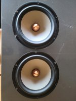
Dayton Audio RSS265HF-8 is designated as a subwoofer. A 47l box provides Q=0.707 and F3=38Hz, which seems excellent for a sealed box of this size. Reducing box size to 40l provides Q=0.73 & F3 of 39 Hz. I generally prefer the sound of sealed woofers over ported ones, so the 40l box size is OK, and PEQ with the planned Hypex FA253 plate amp could provide even deeper bass performance or equal bass performance in a smaller box. Using the 250W maximum power output of the Hypex FA253, I calculate max SPL at 39Hz in the 40l sealed box to be ~106 dB@1m. The 14.3mm Xmax (if that means ∓14.3mm) promises good responsiveness to bass EQ, too. The high 7.7kg mass, 3X that of the NE265, is the only real downside -- and the fact that it’s a sub driver suggests FR above 100Hz may not be ideal, though factory specs don’t show anything untoward to 500Hz.

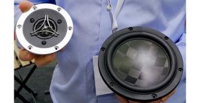
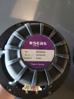
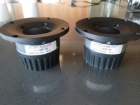
An SB Acoustics SB29NRX75-8 isn’t exactly on my shelf, but four of them are used in my LX521-inspired OB 4-way dipoles. A pair could be pulled for development purposes -- and Solen also delivers these pretty fast. A 53l box with SB3 alignment provides F3 = 32 Hz. Good, but the box is a bit too big. Reducing box size to 40l gives F3= 37.5Hz, slighter lower than the Dayton in the same box. Accepting 200W as the power limit, maximum SPL at 37.5 Hz should be ~108 dB, assisted by the higher 88 dB/2.83V sensitivity. One downside of this woofer is its oversize frame (290mm diameter vs ~265mm for the others), which dictates a wider baffle, likely >310mm, whether or not this is needed for the mid + tweeter.

Hybrid A2 driver ideas

First of all, please have patience with my LazyCAD schematics. At the age of 44 I'm way too old to learn how to use new softwares...

Over the years I have developed a nasty habit of pushing some of my tubes into class A(B) territory by driving the grids positive. I currently have two pairs of monoblocks with triode wired 807s (SE and PP) that operate in peak A2 by using direct-coupled, high gm cathode followers between the gain stages and the output tubes. My most recent build, an 808 SET, works the other way around with the grids idling at +28V or so and only goes negative (A1) at close to max power. This amp used pentode wired 807s as CF drivers.

My next project will be a smaller SET using Taylor T20 and TZ20 as output tubes. These are smallish thoriated tungsten triodes capable of 20W plate dissipation and a mu of 20 and 66, respectively. I intend to operate them at ca. 400V 50mA with 10k plate loads and positive bias, around +12V for the T20 and +20V for its higher mu brother.

This calls for a driver stage with the following specifications:

* Adjustable to allow both types of output tubes to be used

* Capable of swinging +-50V or so into a non-linear load. Max grid current will probably be somewhere between 25 and 50mA at the peaks, hard to tell exactly from the old datasheet. The biggest problem appears to be the sudden change in load when the grid goes negative and ceases to draw current.

* Slow/delayed startup. My output tubes where hard to find and not particulary cheap so I want to be as nice to them as possible. Assuring that they are biased into cutoff until the filaments are hot and the B+ is up is one way to do this. Imagine where all the electrons will go if the filaments are hot and the grid voltage goes positive before the plate voltage...😱

* Good looks. Perhaps a bit childish but I've invested some money in a few pairs of these tubes and a nice set of shrouded transformers/chokes and it would be nice to keep the vintage feel intact by avoiding "modern"-looking tubes. Compromises could be made in this department though...


So, the easy way to do this would be to do it as I've done it several times before: A choke loaded cathode follower direct coupled to the output tubes grid. The small problem here is that the tubes that have the righ vintage look (octals or older) usually has too low transconductance to make good cathode followers.
"Modern" novals such as 6E5P, PL802 etc would be much better for the job but they simply don't look right next to the output tubes.

Mosfets would be even better (and would of course be hidden inside the chassis) but they lack the delayed startup that I would get from an indirectly heated tube. This could probably be solved by slow-ramping power supplies and/or a timer circuit that holds everything in place until all the voltages are where they should be.
Or, we could aim for the best of both worlds by going hybrid:

hybriddrivers.jpg

Drawing 1 shows a hybrid cascode follower where the drain voltage to the Fet is supplied by a trioded EL36. This would delay the drain voltage during startup, reduce it from over 200V to perhaps 30V and keep it much more constant during (which should reduce the impacts of the fets internal capacitances). Should do a decent job if it works at all.

Drawing 2 shows a sort of Super Triode/cascaded follower where a smaller triode CF drives the mosfet. Here the mosfet will have to handle more voltage/heat and large VDS variations but it should on the other hand be completely protected from voltage surges etc. on the input during startup. Bonus idea: Assuming a triode that can handle 400V at idle plus some swing, we could connect its plate to a tap on the output transformer and get a little bit of local feedback for free.

Any thoughts on this? None of these circuits has been tested (or even simulated) by me.
I've browsed through a lot of schematics where mosfet followers are used to drive control- and/or screen grids and there is rarely anything mentions of what happens during startup, perhaps I'm just creating problems in my head?
  • Like
Reactions: astouffer

At long last, actually writing a post

Hi, everyone. As seems to be the custom in these introductions, I guess I'll disclose that I've been reading threads here since 2020.

That would be sometime in the late spring of '20, to be more exact... not long after my downstairs neighbor finally came up to complain about the constant muffled drone of my not-so-apartment-friendly system, which by that point in the pandemic lockdown cycle must've been coming from his ceiling 10 hours a day (and night).

The exchange precipitated the arrival of a pair of Sennhieser HD-6XX's and a Bottlehead crack amplifier kit at my doorstep and, well, here we are.

These forums were ultra-helpful in the crash electronics course that I gave myself in those days, so thanks to all of you. Overall, I've been into hifi since I was a teenager. The DIY thing is relatively new for me, but I'm the sort who always needs a project...no matter the area of interest...and hifi is pretty attractive because my taste in electronics tends to far exceed my budget. Which brings me to the reason for this post:

Recently, I ran across the opportunity to build a turntable. I have a GREAT working motor, platter and other internals, but everything else.... plinth, arms, plans, fabrication will be from whole cloth. I'll start a thread with all the details and some images in the Analog Source forum once I'm cleared here. Hopefully some of you (and within 'some of you' I definitely include @6L6 ) will be interested in following and offering a bit of guidance. Thanks and cheers!

Radian 951Be vs 18sound ND4015BE

Hi,

Any thoughts on pros and cons of these 2?

recommended crossover is 700hz for the Radian 951be but 1000hz for the 18sound ND4015be
Rated frequency range is 500hz to 20khz for the Radian 951be and 900hz to 20khz for the 18sound ND4015be although many people implement these much lower.

If i want to use these for mids and high frequency are the 4"diapgram ok or should i got with 3"?


951bs vs 4015be.jpg

Comparing "Good" SMT Capacitors - C0G vs. PMMA (Acrylic) vs. PPS

We have more options than ever for SMT caps these days. Manufacturers are beginning to designate some types "for audio," and frequently tout the measured performance of these "good" SMT caps against the clearly inferior X7R types for dramatic effect. Yet we seldom see comparisons of the various "good" types against each other.

I'll start with dielectric absorption and hope that other members will chime in to share other important considerations, including subjective preferences 🙂

I found that by combining data from the following sources, I could draw a general comparison of dielectric absorption between the "good" surface mount cap types, including:

- Class 1 ceramics (C0G)
- Acrylic film types (PMMA)
- Polyphenylene sulphide film (PPS).

--
Here's PPS vs. PMMA vs. X7R, from an older Panasonic ECPU datasheet:
Film Chip Capacitor ECHU(B) Datasheet
928242d1614804158-comparing-smt-capacitors-c0g-vs-pmma-acrylic-vs-pps-pps-vs-acrylic-dielectric-absorption-png

Eyeballing it: PPS 0.1%, PMMA 0.8%.
---

Rubycon's PMLCAPs (MU series) have near identical dielectric absorption compared to the Panasonics. From the PMLCAP technical notes:
PMLCAP Technical Notes/Hybrid, Capacitor, Power Supply Units
928243d1614804158-comparing-smt-capacitors-c0g-vs-pmma-acrylic-vs-pps-pmlcap-acrylic-dielectric-absorption-png

They measured 0.21%-0.96%.

---

It's harder to find comparisons of the SMT film caps with C0G. I think manufacturers like to compare their films with X7R because the difference is more drastic. But Kemet offers this chart in a technical article:
Advances in Class-I C0G MLCC and SMD Film Capacitors
928244d1614804158-comparing-smt-capacitors-c0g-vs-pmma-acrylic-vs-pps-pps-vs-c0g-dielectric-absorption-png

A Rosetta stone of sorts. PPS is in the ballpark of the Panasonic bar graph 🙂

---

Putting it all together:

C0G - 0.5%
PMMA - 0.2-1.0%
PPS - 0.02-0.1%

Wow. PPS is an order of magnitude better! Cyril Bateman would be pleased.

Attachments

  • PPS vs Acrylic Dielectric Absorption.PNG
    PPS vs Acrylic Dielectric Absorption.PNG
    42.6 KB · Views: 2,489
  • PMLCAP Acrylic Dielectric Absorption.PNG
    PMLCAP Acrylic Dielectric Absorption.PNG
    29.3 KB · Views: 2,468
  • PPS vs C0G Dielectric Absorption.PNG
    PPS vs C0G Dielectric Absorption.PNG
    20 KB · Views: 2,433

VituixCAD Accuracy

Hello,

I have a general question about the accuracy of VituixCAD. I have been using it for a month to simulate different type of speakers, mainly two-ways and three-ways. I exploited all the important tools such as crossover, diffraction and enclosure simulations. I chose drivers from Dayton so I didn't need to create my own FRD and ZMA files. My question is: how reliable is it as a simulation tool? Are there any specific areas where it might produce errors? Would you build a speaker only according to the data from the simulation, without measuring the drivers on the actual baffle/enclosure?

Thanks!

Hello All! Looking for help! - protection cirtcuit on a Sundown SAEv3-1500D

My name is Patrick, I live in Des Moines, IA. I’m originally from Grand Rapids, MN. I’m trying to get into repairing car amplifiers, and am attempting some repairs, have set up a bench testing station and repair station in my house. I’m excited to talk with people here, and really looking forward to learning some things from you guys who are experienced in this field. Does anyone know a good site to use for schematic diagrams by chance? I’m having a tough time finding a schematic for a Sundown Audio SAE-1500D v3. It flashes protection light when powered up. It looks like it has a burned diode (Marking says S30) on the 12v Offset Protection Circuit. I included a picture, in case anyone can confirm that this is indeed what I’m looking at? I got this amp off EBay to repair and to start learning the trade better.
Thanks,
Patrick

Attachments

  • 9BA80F04-9947-4CCA-A37B-BE118200FE32.jpeg
    9BA80F04-9947-4CCA-A37B-BE118200FE32.jpeg
    654.5 KB · Views: 92
  • 6F75F47F-532E-4A25-B563-9C1FC0FB555B.jpeg
    6F75F47F-532E-4A25-B563-9C1FC0FB555B.jpeg
    561.4 KB · Views: 86

Focal FDP 4.600 won't start up reliably

Man I've been poking at this one for awhile..

This amp does not appear to be going into protection but does not start up reliably. The output stages do not start up and go into oscillation - at first..

After many power cycles and repeated attempts to boot it, it eventually does start firing up and works as expected on all 4 channels. It then starts reliably until I let it sit for some hours/day.

I eventually found that if I discharge the 4 bias capacitors (150u), I can then get the amp to immediately go back to malfunctioning.

I have struggled to find a similar design schematic but believe I finally found something similar in the uCD Super Lite design.

There are no off the shelf half bridge drivers in the amp, it is essentially a discreet design.. but as I said the Super Lite design seems quite close at least for the high and low side drivers. I need to dig further obviously..

Things I have eliminated:

Took the amp from a non working state, sat for days. Tried to boot with a very high amperage supply. Same.

Added speaker loads to outputs while trying to boot from a bad state. Same.

Looked over board very thoroughly etc etc.

Attached basic pic from internet, can grab more pics later.

Attached pic from Super Lite schematic. C20 is similar to the bias capacitors on the focal.

Attachments

  • IMG_1028.JPG
    IMG_1028.JPG
    668.8 KB · Views: 101
  • Screenshot_20240608-120156.png
    Screenshot_20240608-120156.png
    75.2 KB · Views: 111

For Sale Toshiba 2SK170GR NOS

Sell 5 bags each with 50 pieces Toshiba 2SK170GR (Toshiba BATCH CODE 2G & 8A), these are packed in an ESD bag. These are original Toshiba J-Fets, asking 150€ per bag + 5% PayPal fee + registered shipping. Preference is given to buyers from the EU, worldwide shipping is also possible but must be arranged, all shipments are sent by registered mail. Shipping outside the EU can be arranged but takes a few days.

30 Pieces Toshiba 2SK170V NOS​

https://www.diyaudio.com/community/threads/toshiba-2sk170v-nos.396337/

Attachments

  • 2SK170GR  (1).jpg
    2SK170GR (1).jpg
    328.1 KB · Views: 80
  • 2SK170GR  (2).jpg
    2SK170GR (2).jpg
    241.8 KB · Views: 76
  • 2SK170GR  (3).jpg
    2SK170GR (3).jpg
    164.8 KB · Views: 73
  • 2SK170GR  (4).jpg
    2SK170GR (4).jpg
    307.3 KB · Views: 74
  • 2SK170GR  (5).jpg
    2SK170GR (5).jpg
    235.4 KB · Views: 75
  • 2SK170GR (7).jpg
    2SK170GR (7).jpg
    240 KB · Views: 74

I want a cost effective passive 3-way xover to mate GRS 12PT to GRS 6PT plus "whatever" tweeter

the system would be a small (L100 size) reflex with woofer to midrange having good poer handling and hopefully a clear midrange, I'm having a lot of pain issues but wrose, sision issues so cannot see my monitor well (looks washed out to the point that light graphs in hornresp disappear). FWI I gave a look at GRS12PT in Xsim w. Zobe l and not sure if its on-axis rise would be a problem or not summed to mid if xover is in the 350-500Hz region. MAdybe a 3r order for 12PT? - -notchi filter? - I've got to keep the thing cheap.

Also - would a cardboard tube T-line coming out the back be preferable with 6PT to sealed?

Anyhow - trown some values you would use for starters for the woofer and mid

The tweeter dould b a hor+CD, GRS dome or horn - or maybe my old CAT 37-8 if cn locate

I have a lot of Audio Semiconductor Components for sale but am I wasting my time trying to sell them on here?

I have a lot of Audio Semiconductor Components for sale but am I wasting my time trying to sell them on here? I was under the impression that they were difficult to find and sought after, but I have been contacted by quite a few people but only one person has grabbed any so far. Is there a positive thread on here for good sellers?

Seeking Opinions on ScanSpeak CCB5075 Compact Classic Bookshelf 2-Way

I came across this kit at Madisound and Solen lists it as well. I later found it on ScanSpeak’s website so it appears to be designed by or for them (or maybe approved?). It is a small 5.5 liter bookshelf using a 15W/8534T00 5.5”/15cm midwoofer and a D2010/852100 0.75”/20mm dome tweeter. The kit price from Madisound is $749 including crossover. There are no reviews that I can find so I am hoping someone at DIY can critique or provide opinions on this design.

Madisound CCB5075

This design interests me for a small 10’x12’ room and I prefer not to use a subwoofer. According to the write-up this design is supposed to sound much larger than the small enclosure would suggest. My interest is mostly rock music no louder the 85dB without a sub. I would likely use a Buckeye Amp with 150 watts per channel @ 8 ohms.

In addition to the ScanSpeak design and driver sheets I have attached a frequency response graph generated from mh-audio.nl.

MH Audio BR Box Calculator

Thank you!

Attachments

A couple questions on Solid State PT to be used on Tube amp

Hello all,

I recently bought a transformer that had formerly been in a Sony STR-DH190 solid state receiver. The specs say that this receiver was capable of about 100 watts per channel. It's quite large and heavy. I've read online that these transformers can be repurposed as PT for lower-voltage tube amps, given that their secondaries are frequently rated in amps as opposed to milliamps. Some have even argued for using voltage doublers, which I've done myself in a different tube amp; it worked fine.

2024-06-15 09.46.25.jpg


The PT has a pair of primary wires and two sets of secondaries. One is a set of five thin wires, divided into 2 and 3 (center tapped). The second is a set of five larger wires, with one center tap for the remaining four wires.

I measured the primary resistance at 1.6 ohms. The secondaries all measured between 1 ohm and .3 ohms, as shown in my pencil drawing.

I put a 24 volt (no-load was 28 volt) AC transformer on the primaries and measured the secondaries. Then I applied a factor of 4.35 to get to what the approximate no-load voltage would be at 122 VAC.

The smaller secondary pair is 8VAC. The center-tapped smaller secondary is 21.83 VCT. The larger secondary is 65VCT and 89VCT.

So here's my question. I was playing around with a pair of 32L7GT tubes. They are combined rectifer/beam power tetrode. They need 32.5 volts on the heaters at .3 amp, and 90 volts on the plates and screen, drawing a combined 29ma per tube.

I was thinking I could derive my heater voltage from the 65 VCT secondary running the heaters in parallel, and then get my (approximately) 90 volts from the 89VCT secondary. However, I don't know if you can or should take power from both legs of a single center-tapped secondary; I've never done that before. I was thinking I could use the smaller secondary's 8 VAC output to run a solid-state pre to feed the tube input.

I realize this is all an exercise in WTF, but I'm just playing around for fun. Can I get away with it?

2024-06-15 09.46.36.jpg

Suggestions for a Full Range Driver with Moderate Xmax?

Hi all,

Browsing around, just looking at options. I like full range drivers and the sound, even whizzer cones. I'm curious about what options anyone can suggest for any size driver with moderate xmax. Something greater than 4mm basically I guess I should say. Not expecting crazy, but something closer to 6~7mm real world excursion capability? Mainly looking for something that would do well in a fairly larger volume bass reflex tuned down to say 40~60hz, mainly closer to the 60hz side, but I would absolutely entertain something that could do a 40hz range even.

I'm been looking at Mark Audio, Fostex, Lii, Seas, etc, on Madisound and a few others places. But is there anything else suggested? Not looking to go too exotic in the several-thousand dollar range. But anything fun in the $300~400 or less range would be open for playing around with a build. It would be used with active DSP to be able to EQ things as needed.

Currently using a pair of Visiton BG20's, 8" with whizzer cones in sealed cabinets. I'm going to re-do them in a bass reflex around 1.5 ft^3 tuned closer to 50hz I think. But before I do it, I'm curious if there are some other drivers that would be better at this. Use is music only. Not trying to be super loud. Will couple with a subwoofer. But I like low crossovers, so I'm trying to get down to 60hz or so before I need to integrate a sub.

Very best,
  • Like
Reactions: Lawnboy

For Sale TangBand 3" Dome Midrange 75-1558SE - Unused

6 pieces of Tang Band 3" dome midrange original edition 75-1558SE. These are all from before they stopped production.

I'm asking £100 GBP each + P&P. I'm in the UK but can ship anywhere you like. They are $180 USD on Parts Express.

Lots of Photos HERE

20240527_142932.jpg

20240527_141504.jpg


Additional Measurments at Hi-Fi Compass.

I have measured them to ensure they are all working properly.

Two of these (Sample 1 and 2) were built by the by the "master engineer" at TangBand. The others were purchased from Parts Express.

Based on the response below (separated 10dB for clarity) I would pair match:

S1 and S2
S3 and S6
S4 and S5

Individual responses measured at 2.83V @ 20cm

1716757474331.png


1716755644611.png


1716755685199.png


1716756685917.png


1716755777754.png


1716755802417.png


1716755835514.png

CCL0130 and CCLH100 _ is there anything that can do the same job in a circuit ?

Hi ! in another thread i saw a very interesting circuit The one here below Dont consider the writings

1718095556294.png


are there parts than can replace the current limiting diodes CCL 0130 and CCLH100 and do the same job ?
if i understand well this circuit should work very nicely as unity gain buffer
The diodes are not very easy to source What could be used instead ?
thank you very much indeed and have a nice day

Balanced audio summing mixer

Hi!

I'm looking for a way to mix two balanced audio stereo signals. I've got two PCs right now, and I'd like to be able to connect and listen to both at the same time from a single amp without switching between inputs.

I can find plenty of passive SE summing mixers, but I can find none for balanced audio that also have volume control built in.

Before I wandered over to the DIY section, I wanted to see if anyone here knew of existing solutions that would work with no extra DIY work.

Thanks!

For Sale Svetlana 6D22S half-wave rectifier tubes

For sales 21 pieces Svetlana 6D22S half-wave rectifier tubes. Tubes from 12 / 1991 (18) and 10 / 1989 and 2 original packing
Russian damper Diode 6D22S. the 6D22S is similar to EY500. All from Svetlana factory.

Filament voltage: 6V Heater current: 1.75 A
Anode Current average: 300 mA Anode pulse (Ua = 50 V): 1000 mAh Reverse voltage anode pulse: 6 kV

They are designed for quite high currents; a pair delivers 300 mA continuous current at 1 kV or more. It is important to note that the cap is connected to the cathode, NOT the plate.

The 6D22S can also be used in bridges. You have to pay attention to the insulation values of the filaments.

Asking for 120€ for all Tubes shipping is not included

The 6D22S can be shipped worldwide with Germans DHL plus 5% PayPal fees. Registered Parcel only.

Attachments

  • Diode 6D22S (1).jpg
    Diode 6D22S (1).jpg
    229.1 KB · Views: 49
  • Diode 6D22S (2).jpg
    Diode 6D22S (2).jpg
    251.6 KB · Views: 44
  • Diode 6D22S (3).jpg
    Diode 6D22S (3).jpg
    189.4 KB · Views: 43
  • Diode 6D22S (4).jpg
    Diode 6D22S (4).jpg
    275.8 KB · Views: 48
  • Diode 6D22S (5).jpg
    Diode 6D22S (5).jpg
    154.3 KB · Views: 46
  • Diode 6D22S (6).jpg
    Diode 6D22S (6).jpg
    134.1 KB · Views: 48
  • Diode 6D22S (7).jpg
    Diode 6D22S (7).jpg
    280.5 KB · Views: 51

Design of C-core nanocrystalline GM-70 output transformer

Hi,

I'm trying to desing single ended GM-70 output transformer using nanocrystalline C-cores and I need some help because this is my first approach to OPTs.

Design assumptions:
  • core: double nanocrystaline C type cut core (same size as AMCC-400) per OPT
    nanocrystalline material annealed in transverse magnetic field (the most narrow and linear B-H loop)
    Bmax=1.25T
  • single center custom FR-4 bobbin
  • 30W, anode current up to 100mA
  • using OPT_da desing tool
  • winding with numeric winding machine
  • OCC copper for windings (not for prototypes ofcourse)
  • Nomex insulation (also in final version)
  • for first try only 8Ohm output

Newbe ideas:
  • number of turns in sections - an integer multiple of turns of single layer (to keep windings smooth)
  • 17 sections (9 primaries in series and 8 secondaries in parallel)

My first attempt:


OPT_da_1.JPG


Questions:
  • does it make any sense? 🤔
  • Fo=30Khz seems to be low?
  • bobbin is filled only in 50% (16,6 of 35mm) - is it a problem?
  • should I be concerned about calculated resonant freq of primaries/secondaries?
primary:
OPT_da_1a.JPG

secondary:
OPT_da_1b.JPG


Project files in attachement.

Thanks for any help.
Marek

Attachments

For Sale Toshiba 2SK117GR & 2SK117BL

for sale 260 pieces 2SK117GR and 200 pieces 2SK117BL - all Fets are 100%. I bought from German Toshiba distributor Spoerle electronic. As you can see in the pictures, the 200 pieces 2SK117GR (2.6-6.5mA Idss) are still in the original blue packaging from Toshiba.

Two of the Toshiba 2SK117GR are equal to one 2SK170BL with slightly higher amplification, with lower capacitance and also with lower resistance. Minimum order 20 pieces for 65€.

The Fets can be sell worldwide with Finnlands Posti or Germans DHL plus 5% PayPal fees. Registered Parcel only.

Attachments

  • 2SK117GR, & 2SK117BL (1).jpg
    2SK117GR, & 2SK117BL (1).jpg
    169.7 KB · Views: 77
  • 2SK117GR, & 2SK117BL (2).jpg
    2SK117GR, & 2SK117BL (2).jpg
    465.2 KB · Views: 87
  • 2SK117GR, & 2SK117BL (3).jpg
    2SK117GR, & 2SK117BL (3).jpg
    259.9 KB · Views: 82
  • 2SK117GR, & 2SK117BL (4).jpg
    2SK117GR, & 2SK117BL (4).jpg
    150.7 KB · Views: 74
  • 2SK117GR, & 2SK117BL (5).jpg
    2SK117GR, & 2SK117BL (5).jpg
    224.3 KB · Views: 73
  • 2SK117GR, & 2SK117BL (6).jpg
    2SK117GR, & 2SK117BL (6).jpg
    219.7 KB · Views: 74
  • 2SK117GR, & 2SK117BL (7).jpg
    2SK117GR, & 2SK117BL (7).jpg
    165.6 KB · Views: 76

Onkyo M5060 R

Hi all,

I am having some trouble with my Onkyo M5060 r.

I use it in pair with its P3060 pre amp.
I am running a pair of JLB4311.

From time to time, the amp will turn red (from.the operational green) and will go in protection mode. I believe.

I am not sure on the cause.
One channel will go with a brum in it....

Can anyone help me out, hold my habd type of, and walk me through a diy attempt at repairing it?

I used to love changing a diode, transistor here and there in the past. So I am not that atehnical. But I will struggle for something this advanced.

Anyone that wants to embark on this newbie challenge please know...you will dictate the pace. I can't afford to have demands to finish it in 2 days type. You're the lead and I am the apprentice.

Thanks in advance.
I do have my soldering kit, my multimeter and the schematics.

NAD 3130 low level switch clicking when depressed/released

morning-
i wonder if i any of you guys have an opinion on something ive tried resolving many times without any success, and this is a common problem with these units

The low level switch clicks when depressed
now i have taken them out, stripped them down and cleaned them, swapped them with others, ive even tried replacing the 2 muting FETS and the resistors in the circuit, but to no end, so i just wondered if you had any thoughts on it
Ive been all over the muting circuit and low level switch, and can find no evidence of noise with the scope, other than the scope changes very slightly(jumps) when the switch is depressed.

Its more anyoying than anything because i cant find it and have this on 90% of the units ive had though my hands, and now i want to find it once and for all.

cheers

paul.

Attachments

  • 3130 click.jpg
    3130 click.jpg
    177.2 KB · Views: 101

HammerTech LCA 600.1 not oscillating

Hello everyone,

Recently, I received a HammerTech 600.1 class D amplifier with a dead output section. Upon further inspection, I found that two of the buffer transistors were dead as well, so I replaced them with new working parts. Two marked resistors also appeared to have been drawing a lot of current, so I replaced them too.

Everything now checks out okay in and out of the circuit, but there is no oscillation on the outputs, and the amplifier turns on normally without going into protection.
Also removing those two marked zeners will result in some oscillation but it's not fully forming the pwm signal and sounds very distorted.
sketch-1717584080671.png


Can anyone be kind enough to help me find out what the problem is?

Thanks in advance.
IMG_20240605_014719.jpg
sketch-1717583351954.png
sketch-1717583376039.png

Hi everyone! - Question about Monsoon computer speaker

Hi Folks,

Just joined this forum last night.

Apparently I'm 20+ years late to the Monsoon computer speakers party! Found at Goodwill for $8.49 a Monsoon MH-505 speaker system, missing power supply and rear speakers. They looked 'cool' so I decided to take the chance and bought them.

Once home I decided to by-pass the sub (since I didn't have power for it anyway) and cut the RCA plugs off the front speakers and connected them to my FosiAudio BT20A amp. Then, plugged the amp into my old DragonFly Black USB DAC and fired up Spotify. Played an old fav, Holy Cole's "Invitation to the Blues" WOW - imaging and clarity was stunning - totally want to know more about Planar! Spent the next two nights Googling Monsoon.

My main focus is to keep these as computer speakers, focusing on music, NOT games.

Have a few questions, if anyone would be willing to share? Please keep in mind I'm a total noob compared to most folks on this site, sorry... Also, family life forces me to stay under $300 budget. 🙁

1) The 3" cone woofer seems a bit 'weak' - can they upgraded fairly easily and cheaply (ie for less than $100)? Is this complicated by an internal cross-over in the front speakers or just a simple replacement in existing enclosures and circuitry? I found on another forum someone stating they were upgrading them using Peerless PLS-P830985 or Dayton Audio PC83-4. Would this be a big sound improvement.

2) I've read the MH-505 sub is 'okay', but not great. Got power supply for sub today and hooked things up skipping the FosiAudio BT20A amp... sound stage compressed and everything was much 'thinner' sounding... not sure if that's expected or if the amp is bad in the Sub... I've seen a few posts where folks use other subs but most don't allow cross-over above 180Hz, which is still too low for the front speakers.

How about this, (from another forum), use Dayton Audio DSP-408 4x8 DSP and a BESTIAN Powered 6.5" Home subwoofer. I'd still use the FosiAudio BT20A to power fronts.

3) Would a later model 'Monsoon PlanarMedia 14' system (if I could find one in good shape) be better sounding with later planar panels and skip trying to customize the MH-505's

Any suggestions greatly appreciated!

Thanks!

Why do a lot of songs from around 1972-1973 have a unique sound to them, while other periods dont?

I've noticed that A LOT of songs from the ~1973 time have a certain... warm, low pass sound to them. Was there some unique piece of gear used at that time? I don't hear that in music from any other period...
Some examples:
Browning Bryant - Blinded by love, 1973: https://inv.n8pjl.ca/watch?v=Clz6fXwTOs4
Vincent - Don McLean, 1972: https://inv.n8pjl.ca/watch?v=ajX26nIYpUE
Marc Benno and the Nightcrawlers - Coffee Cup, 1973: https://inv.n8pjl.ca/watch?v=Ck6YKqfL3y0

And when trying to compare songs from that period, it's hard to tell what "the sound" I'm hearing is, but whenever I hear a new song with "that sound" I instantly think it's 1973, which it always has turned out that it indeed is.
The odd thing is it's not just american records, it's also songs from the UK.
  • Like
Reactions: Juhazi

For Sale Focusrite Scarlett Solo 2nd Gen

I bought this several years ago to test THD of some circuits, but only rarely used it since I've basically stopped building new things. Includes original USB cable and box. I wasn't interested in using the included software, so have not registered the Solo, which should mean that the software is available for whomever buys this.

Asking $50 plus actual shipping to your location. Payment by PayPal. SOLD

20240325_113958.jpg

For Sale Heatsinks

Looking to get rid of some heatsinks that I no longer expect to use. PayPal is probably easiest for payment. Will ship within the US at buyer's expense. The heatsinks all fit into a medium flat rate USPS Priority Mail box, so can ship for $18.40. Other carriers can be considered at your request, but they are unlikely to be cheaper. Will consider shipping to other counties, but this is likely to be expensive. Local pickup in western Illinois is also a possibility, as is meeting part way if schedules line up to allow travel.

Three black anodized heatsinks which have a grid of holes drilled and tapped in the base. Some scuffs and fins on the sinks. Each sink measures about 7.875" wide, 5.875" high, 1.5" deep with a 0.375" thick base, so the fins are about 1.125" tall. Each sink weighs about 3.5 pounds. I've tested these at about 30W dissipation per sink with comfortable temperature rise. Asking $20 for all three. SOLD

Note that measurements are rounded to the nearest 0.125" for simplicity and weights are approximate as my scale's accuracy is questionable.

Attachments

  • 20230713_132642.jpg
    20230713_132642.jpg
    542 KB · Views: 310
  • 20230713_132619.jpg
    20230713_132619.jpg
    510.8 KB · Views: 299
  • 20230713_132559.jpg
    20230713_132559.jpg
    796.6 KB · Views: 310

Anthem PVA-7 - Strange Oscillation

Amp is FIXED!!!!! - see Post #54-57 for the specifics of the repair.

I bought a used PVA-7, knowing that it might have some problems. Powered up on the DBT, 60w, 75w, 150w - no issues. Checked for DC on all the outputs - none were higher than 20mV. So I moved to testing with an 8r dummy load resistors, still on DBT with no issues. Took the amp off the DBT and tested with 500Hz and 1000Hz sine waves into the 8r dummy loads up to about 50% power - again no issues.

Here is where it gets weird - connected the amplifier to some low-grade speakers for initial test. At low volumes on sine wave or music (~<1w) it sounds okay and will play. As soon as you turn up the volume on sine wave or music to 2-3w, the bias jumps up from 15mV to close to 1V and the 10r output (zobel) resistor heats up and the amplifier shuts down, protection circuit kicks in This oscillation/overheating takes about 3-5 seconds to kick-in the protection, depending on how much you turn up the volume.

I tried the same test with only the faulty channels (2 channels on a single heatsink) on DBT and will play fine up to 27Vac (max preamp volume) on the speaker outputs as long as it's playing into an 8r dummy load. As soon as I connect my speakers (~6.7r nominal load) it will cut out at around 75% volume and you can see the current ramp-up in the DBT. As the DBT lights up, so does the 10r resistor on the output.

Final test was to try each channel separately and it appears it is only on one channel, I can hook up the other channel to the speaker and play as loud as I want with no issue. I can connect to the 8r dummy load on faulty channel and still plays up to 75% before protection. But a speaker on the faulty channel or both channels hooked up to speakers and it shuts down quickly.

Amplifier board: I have tested all TO-92, pre-drivers, drivers and outputs to the working channel and everything checks out. Measured every resistor and diode going bad board to good board and they all measure within 1-2%. Output BJTs measure good and no DC on the output - so I'm at a loss to why the amplifier is oscillating.

Also - nothing except a 2N5551 has been changed in the relay circuit. Measured a little low on Hfe, so I changed it out. Everything else, including solder joints all look original - not been touched.

Can this be capacitors? I know typically you would add, change or revise capacitors in the circuit to kill the oscillation, but since this is totally stock, could it be a bad capacitor in the circuit causing the oscillation?

Attachments

  • IMG_7214.JPG
    IMG_7214.JPG
    598.1 KB · Views: 182
  • IMG_7215.JPG
    IMG_7215.JPG
    553 KB · Views: 166
  • IMG_7216.JPG
    IMG_7216.JPG
    428.7 KB · Views: 186
  • IMG_7217.JPG
    IMG_7217.JPG
    447.1 KB · Views: 166
  • IMG_7218.JPG
    IMG_7218.JPG
    454.1 KB · Views: 166

Quad 12L Active Monitor schematics?

Hi Folks, I'm looking for the schematics of the Quad 12L Studio Active monitor. One of mine has developed an intermittent crackling noise, that I want to track down and fix. I've posted this in the chip amp section, as I know these things use a pair of chip amps! I can probably reverse engineer them, and will if necessary, but thought I'd see if I can save myself the trouble... Thanks in advance! Dave

Help with a Peerless SLS 8

I am having trouble with my Peerless SLS 8 for my 3 way. I have taken actual theile small parameters using REW. When I enter those into WINISD I always end up with a weird hump. Stock parameters for the Peerless SLS 8 is dead flat. I will show the parameters, the graphs, and the box.

Does someone know of anything I can do to fix this? I planned on crossing it over at 300hz but I fear I will end up with an odd dip between 80-200 hz.
Stock line is red, actual measured theile paramters is pink.

Attachments

  • sls thiele.png
    sls thiele.png
    27.2 KB · Views: 68
  • Screenshot 2024-06-11 135628.png
    Screenshot 2024-06-11 135628.png
    38.9 KB · Views: 70

ST1000a, aligning the FM alignment tool

I am making progress fixing and "calibrating" this classic calibrator.

20240615_061313[1].jpg
Backstory:
(or skip down to the maroon coloured text to see my concerns/issues}

I am attempting to rehab a 70's FM tuner (Luxman t110u).
So, I found this dusty Sound Technology ST1000A at my local surplus dealer - no fuse holder, loose switches, unknown functionality.... $100.
At my bench, I fixed the fuse and decided to replace the main PSU filter caps. Good thing, because one of them was bad and had turned into a wayward resistor.
(they were 1500uf each rail, but I went for 2000uf each.)

20240615_063802[1].jpg
Then, through an ammeter, I plugged it in to my variable AC transformer, flipped the ST1000a power switch and slowly turned the voltage up to 120v ...keeping a close eye that the ammeter did not spike.
All seemed ok, and it showed signs of life.
After a long sleep, it curiously opened it's dusty eyes.

I cleaned and lubed the rotary switches. The carbon pots did not seem to need attention. The meter reacted as if it was new.
I began to replace the smaller axial electrolytic caps on the internal board, but every cap I removed tested like new, so I stopped replacing them, for now. Those old Sprague 30D types seem pretty robust !
This must be an early unit, because it includes Opt, M-2, but not with the typical 1k/400hz switch.
Instead, it has 4k/400hz. Curious.

20240615_064104[1].jpg

The manual/service guide is easily found online, and here...... http://www.stancurtis.com/soundtech.htm
An article on "updating/upgrading" the ST1000a is here..... http://www.ham-radio.com/k6sti/st-1000a.htm

Following the adjustments outlined the manual, the ST1000a was close to specs, but everything needed a little tweaking to become spot-on.
I performed one upgrade from the above article, to lower the distortion of the internal wein-bridge oscillator (added two resistors and a cap).
Using my QA403 audio distortion analyzer, before the mod :
3862 Hz (4 kHz) = .027 %THD
393 Hz (400 Hz) = .017 %THD
...after the mod:
3862 Hz (4 kHz) = .0008 %THD
393 Hz (400 Hz) = .0006 %THD

Other adjustment steps from the manual:

152 kHz/19 kHz Crystal oscillator adj.... (C20) adjusted to within 10hz, good.

R/L Gain Balance (38kHz Carrier Suppression) (R1, R7) One trim pot minimizes the 38khz ripple from the upper half of the (sine) waveform, another trimmer does the same to the lower half of the waveform. I think I did it correctly, making both halves of the sinusoidal wave show as little ripple as possible. I can still see a little ripple, but just barely.

DC balance. (R19) Trim to get lowest DC millivolts (less than 20mV) I trimmed to 5mV.

Mono/Stereo Sub-channel Separation. (R35, R38) Here, the guide is confusing. I don't feel confident that I am adjusting correctly.. or to what is wanted.
The drawings are rather vague ?
20240615_082954[1].jpg
I tried Method A and Method B.
Method A, I think I'm trying to get the flattest line across the center ?
Method B, I think I'm trying to get the "cusps" close, but not touching ?

Here are my adjustments, and a pic of the overload-preventing clipping diodes, per the manual instructions:

20240614_215546[1].jpg20240614_215947[1].jpg
20240615_082558[1].jpg

FM Modulator Linearity. (trimmer R52) In this step, I do not have the gear shown in the drawing.
HP 5210a Discriminator
HP 10534a Double Balanced Mixer (50k to 150mHz)

20240615_063825[1].jpg

The 5210a discriminator...guessing this gives you the difference between two frequencies ??
I think I can do that with my counters, including phase differences ?
20240614_224040[1].jpg
The HP 10534a passive mixer....I have one of these (Clarke Hess "active" mixer) but I'm not sure if will work, or if it has enough bandwidth , I've been looking for it's rare manual.
20240614_224050[1].jpg

Modulator Level (trimmers R47, R95) This is to be done after the above Linearity step, so I can't proceed before the Linearity adjustment.
The manual gives a method using an accurate Standard Generator, OR a method for using a Discriminator.

Internal Oscillator (distortion adjustment, R105, R95) I did that, as noted earlier.
Pilot Phase. (R93) not adjusted yet.
L/R Balance (R118) not adjusted yet.
RF Stereo Separation (C16 trimmer) not adjusted yet.

END OF ADJUSTMENTS.

BTW, I built the "ST Model 100" 50 ohm to 300 ohm adapter, as noted from the links above....
20240615_064006[1].jpg

VTL Compact100 Monoblock Blows Fuse

A buddy has a pair of VTL Compact 100 Monoblocks (circa 1988) that have performed well, He recently retubed & reset bias with good initial results. Several weeks later one of the pair began blowing mains fuse. I have SS experience but am a newbie at tubes - my first thought given the age was to replace electrolytic capacitors & check tube associated resistors as well as solder joints & socket to tube pin contact. Am I on the right track or are there other obvious items - also if anyone has a schematic that would be very helpful. Thanks!😉

Seeking Advice for Unwinding an Inductor

The crossover for Dennis Murphy’s CAOW1 2-way speaker design calls for a 0.06 mH inductor with a 0.10 ohm DCR. In his write-up Dennis indicates “You will probably have to order a 0.10 mH inductor and unwind a little less than half of the wire. The value is not critical.”

Dennis Murphy's CAOW1

Dennis is correct so I have some questions about how to arrive at 0.06mH from a 0.10mH inductor, or at least close enough to work:

1. Can I weigh the coil on a digital scale then unwind and remove material bit-by-bit until the coil weighs 60% of the original value? The only thing I would be measuring here is weight of the coil.

2. Would it be better to purchase an LCR meter to measure inductance as I unwind, or is this overkill considering Dennis’ saying the value is not critical?

3. In general, do most people verify the accuracy of other crossover components or trust the manufacturer’s values? If most verify other components I may get an LCR meter to check resistors and capacitors in addition to getting really close with the inductor.

Peak LCR Meter

Thanks in advance for your advice!

Attachments

For Sale XRK BTSB Audio Buffer Board + Discrete Diamond Buffer Bundle

SOLD
A set of XRK Audio BTSB THT buffer board for sale.
A very convenient front end board with good connectivity flexibility, and gain selection by means of dip switches.
More details are here :
https://www.diyaudio.com/community/threads/btsb-buffer-se-bal-to-se-bal-buffer-gb.358142/
My board happens to be the version with a slight error as mentioned in the thread above.
Details of the error here :
https://www.diyaudio.com/community/...o-se-bal-buffer-gb.358142/page-3#post-6330962
A simple change of resistor position would correct this error, and this correction has been done on the board i am selling.
I used an off board bipolar psu for this board and hence did not populate the Murata isolated DCDC. Wires has been jumpered to the connector for +/-15Vdc inputs.

I will also throw in a set of discrete diamond buffer i received from the giveaway from XRK Audio. The default giveaway boards has 'wrong' led on them. I have changed to the 'correct' led part recommended by XRK Audio. They have been tested and working properly. I paid shipping from US to Singapore for these boards. Details of board here:
https://www.diyaudio.com/community/threads/xmas-diamond-buffer-giveaway.405895/
https://www.diyaudio.com/community/threads/jhoflands-diamond-buffer.401231/#post-7522644


The set of BTSB + Diamond buffers + shipping registered & tracking = 95 USD
Paypal FF Only please.

Attachments

  • 20240511_113026.jpg
    20240511_113026.jpg
    504.2 KB · Views: 165
  • 20240511_113048.jpg
    20240511_113048.jpg
    495.4 KB · Views: 183
  • 20240511_143633.jpg
    20240511_143633.jpg
    542.7 KB · Views: 174

For Sale SEAS W22EX001 8ohm, SEAS Prestige 27TBCD/GB-DXT H1499-06 Tweeter

Pair of SEAS Prestige 27TBCD/GB-DXT H1499-06 Tweeter. Gently used, work great. $200 + $10 shipping.

SOLD Pair of SEAS W22EX001 8ohm woofers. 8" magnesium cones. Used, not abused. Not original boxes but will be well packaged.

All were used in an active XO 2 way config.

Attachments

  • 20231001_123214.jpg
    20231001_123214.jpg
    511.1 KB · Views: 94
  • 20231001_123143.jpg
    20231001_123143.jpg
    639 KB · Views: 113
  • 20231001_122901.jpg
    20231001_122901.jpg
    580 KB · Views: 108
  • 20231001_122847.jpg
    20231001_122847.jpg
    631.9 KB · Views: 110

Shunt type volume control for tube preamp

General consensus from what I read is that a straight log pot of good quality is better than any shunt arrangement. So no doubt several replies will confirm this. Downside is that good quality pots, especially stepped attenuators, are expensive.

But supposing, in the interests of economy, you did construct a shunt control for a valve amp or preamp, what is the best you can do? Here we assume a typical DAC input of low output impedance which would be happy into 10K. So I'm assuming that theoretically the shunt resistor should be 10K or more, but please dispute this.

I've made an experimental external box to try out different resistor values. Shunt resistors for first trial are old style black Holco 1W. Pot is 50K log chi-fi Alps. This feeds an amp with a 100K resistor to ground on the input. Results....

38K shunt - law is fine but too much attenuation of the signal
10K shunt - louder and the law is actually quite good.

These are very audibly inferior to a simple 100K Holco input resistor to ground and volume control in software on my Mac Pro with lossless tracks in iTunes.

Please suggest anything that will give better results......

Capacitors test expertise

Hello,

I have few caps

Audyn QS6, Qtext4​

not tested by anyone yet, no reviews at all conducted.
I'm looking for somebody with the expertise and experience willing to do tests and share his impressions.
I'll supply the caps, but based on latest Canadian postage rates, shipping is quite unaffordable/reasonable in comparison to the cost of the caps and else..
Thus I'm looking for somebody in Calgary ( a long shot) and surrounds in order to avoid the shipping charges.
Any other suggestions, please?
Thx

MSB DAC I2S pro format

Dear Sir,


My friend has a MSB DAC which has RJ45 input called I2S pro. DAC feedback the clock to MSB transport. for the rest of the pin should be I2S signal.

Any one know how to connect the another I2S device to MSB I2S pro.

For example, I have philips CDM4 transport which has HDMI and RJ45.


If I know the pin assignment of MSB DAC RJ45. I can make the connection to MSB DAC

slowmotion video project: imploding lighbulbs and tubes

The beauty of destroying lightbulbs and tubes in slow motion

I worked on this film for over a year, with new ideas coming up over time. The slow-motions were recorded with two older Samsung S9 and S10 smartphones, which offer a video function for this. The cameras only record for a period of 0.2s and 0.4s, whereby the triggering of the shutter release is done by movement in the image. Almost 1000 frames per second are recorded (960fps). The sequence is correspondingly short. Despite this limitation, I have lost practically no recording, which is irretrievable in scenes with more material use, such as with the picture tubes. Someone will ask, "Why is it still running so fast, slow motion has to run even slower?" The challenge was to deliver a maximum result with this minimal amount of equipment. On the other hand, the film consists of a lot of individual shots, all of which I want to show. If you were to shoot them with much more time dilation, the film would not last 7 minutes, but maybe half an hour. My intention was to put the dynamics and action in the foreground - you should see how it shreds! 😀

Login to view embedded media

TSA1701 loud cracking noise

Hello,

I'm experiencing a peculiar issue with my audio setup and would appreciate any insights or suggestions you might have regarding the TSA1701 DSP. Here's the situation:

I have two 15-inch subwoofers that are functioning correctly. However, when I connect a third amplifier to the system, there's no sound output—only a loud cracking noise (as shown in a video I have). I've checked to see if the DSP (Digital Signal Processor) is the problem, but the same issue occurs with a second TSA1701 DSP unit.

The problem does not seem to be related to the tweeter or the third amplifier. It arises as soon as I plug the jack into LineOut2. If I only have LineOut2 connected with two loads and then add the third load to LineOut1, the same issue occurs.

I've also ruled out the possibility of the DSP's USB power supply being too weak, as I've tried powering it with 10V directly at the socket. All individual components (2 subwoofers, 1 tweeter, 3 amplifiers) work fine on their own, but the DSP starts acting up as soon as both jacks are plugged in.

Additionally, the cracking noise gets louder when I increase the input volume.

I also tried connecting the tweeter to one of the subwoofer amplifiers, and then one subwoofer and the tweeter played perfectly. However, when I added the second subwoofer, the cracking noise returned.

One thing i thought of, is that because the DSP does have 2 3.5mm output jacks, i used 2 3.5 to RCA Cables. Because i only need one output of the second cable i just cut of the other line. Could it be possible that the error is resulting becuase of this? Should i short the wire i cut, or solder a resistor in between?

Is there any other setting or property of the DSP i have to take care of?

Thank you in advance!

My Setup:
TinySine TSA1701
Hypex SMPS400A400
3* IRS2092 500W ClassD Amp
2* the box 15LB075-UW4 15"
1* Master Audio DR8
t.mix 201 USB Play for Audio Input

Attachments

  • WhatsApp Video 2024-05-23 at 16.28.24.mp4
    3.2 MB

Hello, I'm Thomas!

Hi, I'm Thomas from Austria.
Last year I graduated from a technical college (HTL) in the branch Electrical Engineering - Smart Systems. Starting this fall, I will be studying computer science at the Vienna University of Technology.
Already during my time at HTL we created some DIY audio projects, among other things by designing and producing our own Class-D amplifier boards, and then used them in a portable active speaker.

I am looking forward to participating in some of your contributions and hope for your help in some areas.

Thanks, Thomas!
  • Like
Reactions: krivium

Crown XLS-402 attempted fix made it worse

Greetings. Attempted to repair my XLS-402 which had very low output on one channel. In a moment of brain fade I attempted to clip my scope ground to one of the driver transistor (MJE15032/033) heatsinks, thinking it would be 0V but instead got a wakeup call with a bang and a flash. I was aware the output transistor heatsinks were live I just stupidly didn't test the smaller heatsinks first before looking for a convenient scope ground. Replaced all the MJE but no output at all in either channel now. There is 95VDC on the output heatsinks but nothing on the driver sinks, I assume there was before given the fireworks from shorting it out. Schematic shows these are all connected together, any thoughts out there on why this might be the case?

Cheers

HH VX150 Crippled by VCA cards.

I have a VX150 here. I used to have three of them years ago but sold them. This one had the VCA input cards.

I have recapped this unit as the caps on the main board were going high esr and low capacitance. I stupidly put in 10uF cap in the feedback path on each channel! Of course when I tested frequency response it was down 3db at 20Hz! Anyway, I installed 100uf and then was fine.

I'm surprised how bad the VCA input cards cripple the amplifier. Distortion figures were not that good. 0.05% at 1Khz mid power. This climbed to a very bad 4% at 30Khz!! Also I had to drive it with 5v to get full output! I pulled out the VCA boards and jumpered the links and now much better. Distortion at 1Khz is 0.0045% mid power and the same at 20Khz. Also no hiss even with headphones.

Bias, DC offset and CMR adjusted to spec.

Attachments

  • IMG20240613170024.jpg
    IMG20240613170024.jpg
    222.1 KB · Views: 93
  • IMG20240613165522.jpg
    IMG20240613165522.jpg
    231 KB · Views: 87
  • IMG20240613165524.jpg
    IMG20240613165524.jpg
    304.4 KB · Views: 89
  • IMG20240613165529.jpg
    IMG20240613165529.jpg
    224 KB · Views: 100
Projects by fanatics, for fanatics
Get answers and advice for everyone wanting to learn the art of audio.
Join the Community
507,678
Members
7,883,846
Messages

Filter

Forum Statistics

Threads
406,009
Messages
7,883,846
Members
507,678
Latest member
Medyx