General consensus from what I read is that a straight log pot of good quality is better than any shunt arrangement. So no doubt several replies will confirm this. Downside is that good quality pots, especially stepped attenuators, are expensive.
But supposing, in the interests of economy, you did construct a shunt control for a valve amp or preamp, what is the best you can do? Here we assume a typical DAC input of low output impedance which would be happy into 10K. So I'm assuming that theoretically the shunt resistor should be 10K or more, but please dispute this.
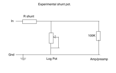
I've made an experimental external box to try out different resistor values. Shunt resistors for first trial are old style black Holco 1W. Pot is 50K log chi-fi Alps. This feeds an amp with a 100K resistor to ground on the input. Results....
38K shunt - law is fine but too much attenuation of the signal
10K shunt - louder and the law is actually quite good.
These are very audibly inferior to a simple 100K Holco input resistor to ground and volume control in software on my Mac Pro with lossless tracks in iTunes.
Please suggest anything that will give better results......
Good idea - drawing coming. I replaced the Holco shunt resistor with an 8.2K 10W wirewound Ayrton-Penny type and that sounded audibly better. In fact pretty good.
The 100K resistor on the input of the amp/preamp, a type 26 DHT stage feeding EL12n outputs, could benefit from being 470K for these experiments. I have the volume control and the various resistors in an external box for convenience.

The 100K resistor on the input of the amp/preamp, a type 26 DHT stage feeding EL12n outputs, could benefit from being 470K for these experiments. I have the volume control and the various resistors in an external box for convenience.

Ok, the series resistor should not be called R shunt, that's confusing.
It's the pot that is the shunt resistor.
Don't go any lower than 10k for the series resistor. The DAC may not be able to properly drive
a smaller series resistor than 10k, when the pot is set to a low value.
But if you prefer the digital volume control, then don't use the pot or series resistor at all.
However, at low volumes, a digital control may lose enough resolution to be audible.
Last edited:
This thread caught my eye.
I agree with rayma
Whether the shunt attenuator is for unbalanced, or for balanced shunt attenuation, 10k series resistance(s) sounds about right.
I need to get busy and draw the schematic of the 2 stage balanced amplifier with XLR input that I designed and built; and start a thread about it.
I used 7 resistors from the XLR to the grids of the input/driver triodes.
But the two 10k series resistors, one for each phase, and a 50k pot across the 10k outputs are the only shunt attenuator parts.
There is about 3dB attenuation insertion loss when the 50k is at maximum resistance. A switch and another 50k resistor in series with the potentiometer makes the loss closer to 1.6dB.
Last edited:
Thanks for that - drawing corrected, end of a long day experimenting.
For my own use in my amp I use a 100K input resistor and volume control in software. This is for the amps or preamps I make in tiny numbers to sell to audio chums who can't build DHT stuff themselves.
I'm encouraged by the good sound of the wirewound series resistor. I've been listening to it and it's a big step up from the Holcos. I don't associate 10W wirewound resistors with shunt pots but they do sound nice. The Takmans seem to be all the rage with shunt pots.

The main disadvantage of shunt attenuator is the variable input impedance.
If you use 10k series resistor, the impedance can change from 10k to 10k+ log_pot actual value // 100k.
If you use it after the low output impedance DAC, it doesn't matter that much.
In my practice (if I use only one source -for example DAC-) the quantity of attenuation almost constant, only 1.5-2 dB variation occurs.
If I use preamp with TVC or good (Noble, TKD) potentiometer, the volume settings not requiring only one click (TVC switch) or small correction of potentiometer.
For this purpose the (fixed value) attenuator with one-two value variation would be appropriate.
The properly chosen fixed values Rseries->Rshunt1 and optionally paralleled Rshunt2 may satisfies it.
High quality resistors not cheap toys, but only 3 piece is affordable. I like Shinkoh tantalum resistors.
If you use built-in (fixed resistor) attenuator in preamp input, the 100k grid leak resistor can be omitted.
As your pot currently wired you don't need the 100k input resistor so remove it if you build the volume control into your pre. If you’re sure you will never disconnect your volume from your preamp while it os on discard the 100k. The 100k is just there to keep the 26 grid connected to ground - the pot is doing that job anyway - so you could easily increase it to 1Meg dump the bugger.
Any modern solid state DAC will comfortably drive at least 2k if not lower (almost any modern opamp can drive 600R without breaking a sweat) so you can reduce the series resistor to 5k and probably ideally use a 10k pot. Your preamp’s 100k input resistor will affect the law of your volume control which is the real reason to remove it.
Any modern solid state DAC will comfortably drive at least 2k if not lower (almost any modern opamp can drive 600R without breaking a sweat) so you can reduce the series resistor to 5k and probably ideally use a 10k pot. Your preamp’s 100k input resistor will affect the law of your volume control which is the real reason to remove it.
As to the variable input impedance as stated earlier modern opamps dont show significant changes in distortion with load until the load gets really low - although the now grizzled TL07x series dont like going below 2k - with a 4k7 series resistor your lowest impedance is 4k7 and almost always more (unless the phone rings and you are silencing the hifi of course) so it wont be an issue. Lower resistances do equate to lower noise but in tandem with DHTs that could be academic.…. but worth a fiddle and listen
Thanks guys - yes, the 100K input resistor will be removed once I've figured out a good sounding volume control to fix inside the unit. I should replace the 100K with something like 470K for testing purposes. With a modern DAC a 10K log resistor with 6.8K series resistor is looking good.
So..... choice of series resistor. Shinkoh tantalum, AN Tantalum, bulk foil..... Has to sound better than the NOS wirewound currently in it. The trouble is we're talking boutique parts and I don't really want to throw money at this experiment. Shinkos from Hi-fi Collective are £12.85. Audio Note tantalum is cheaper at £3.90, with non-magnetic at £6.12
https://www.hificollective.co.uk/catalog/8k2-05w-audio-note-tantalum-resistor.html
https://www.hificollective.co.uk/catalog/8k56-0-5w-audio-note-tantalum-non-magnetic-resistor.html
Charcroft Z Foil are £13.87. Vishay bulk foil hard to find. Riken Ohm equally hard to find. Takman are just pence, very cheap, carbon or metal film.
Comments?
Last edited:
DACT and Goldpoint have both switched to using regular thick film surface mount resistors in their attenuators. Both sites attest to them.
I tried a thick film resistor as cathode resistor in filament bias several years ago and didn't like it at all. Haven't really considered them since. The SMD devices may be different but I'll never use them - everything I build is point to point. But thanks, that's an interesting observation.
If you want to use SMD resistors, dynamic parameters (for example distortion versus temperature) may varies a lot.
Some years ago one of your friend measured many SMD resistors:
https://audiodiyers.hu/viewtopic.php?f=80&t=1387&start=150 (sorry, only in Hungarian language)

Generally larger (0805,1206, MELF) and thin film are better than 0603 thick film.
MELF is interesting.
https://eu.mouser.com/ProductDetail/Vishay-Beyschlag/MMU01020C2001FB300?qs=YmMt7wOBEV4bSX0Ih7Km5Q==
Susumu and Panasonic also quite good.
Some years ago one of your friend measured many SMD resistors:
https://audiodiyers.hu/viewtopic.php?f=80&t=1387&start=150 (sorry, only in Hungarian language)

Generally larger (0805,1206, MELF) and thin film are better than 0603 thick film.
MELF is interesting.
https://eu.mouser.com/ProductDetail/Vishay-Beyschlag/MMU01020C2001FB300?qs=YmMt7wOBEV4bSX0Ih7Km5Q==
Susumu and Panasonic also quite good.
Andy the Vishay Dale are non inductives Ni-Cro like MillsAndy best SQ Vishay Dale RN60-65
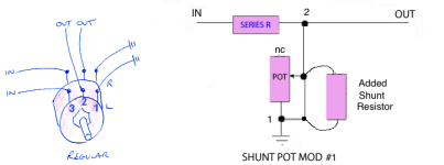
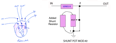
Request for clarification. Which of the 3 designs attached is the right way to do it? What I want to do is use:
1. A series resistor of 12K
2. An added resistor of 24K to convert a 100K log pot to a 19K one
3. A 100K log pot
Options are:
1. alps blue mod (but with an added 24K)
2. mod #1
3. mod#2
I'll try and build these three to see how they function, but if anybody can direct me it would save time!


1. A series resistor of 12K
2. An added resistor of 24K to convert a 100K log pot to a 19K one
3. A 100K log pot
Options are:
1. alps blue mod (but with an added 24K)
2. mod #1
3. mod#2
I'll try and build these three to see how they function, but if anybody can direct me it would save time!


Well, I built mod #1 and it works. I don't know how good the log scale is, but it seems in the general ballpark.
scusa Andy, ero interessato anche a realizzare il potenziometro shunt mod 1 ma non ho capito bene i disegni perché mi confondo con i collegamenti dei pin 1 2 3 che compaiono nei disegni a mano (a sinistra) e quelli fatti su il PC dove compare anche la resistenza in parallelo (a destra). potresti semplicemente postare il disegno del potenziometro shunt mod 1 in modo che sia più chiaro in quali pin dell'alps blue collegare il resistore di shunt in parallelo e in quale pin collegare il resistore in serie. Grazie
Please use English.
sorry Andy, I was also interested in making the mod 1 shunt potentiometer but I didn't understand the drawings well because I get confused with the connections of pins 1 2 3 that appear in the hand drawings (on the left) and those made on the PC where it also appears the resistance in parallel (right). you could simply post the drawing of the mod 1 shunt potentiometer so that it is clearer in which pins of the alps blue to connect the shunt resistor in parallel and in which pin to connect the resistor in series. Thank you
sorry Andy, I was also interested in making the mod 1 shunt potentiometer but I didn't understand the drawings well because I get confused with the connections of pins 1 2 3 that appear in the hand drawings (on the left) and those made on the PC where it also appears the resistance in parallel (right). you could simply post the drawing of the mod 1 shunt potentiometer so that it is clearer in which pins of the alps blue to connect the shunt resistor in parallel and in which pin to connect the resistor in series. Thank you
- Home
- Amplifiers
- Tubes / Valves
- Shunt type volume control for tube preamp