Hi ! in another thread i saw a very interesting circuit The one here below Dont consider the writings

are there parts than can replace the current limiting diodes CCL 0130 and CCLH100 and do the same job ?
if i understand well this circuit should work very nicely as unity gain buffer
The diodes are not very easy to source What could be used instead ?
thank you very much indeed and have a nice day
are there parts than can replace the current limiting diodes CCL 0130 and CCLH100 and do the same job ?
if i understand well this circuit should work very nicely as unity gain buffer
The diodes are not very easy to source What could be used instead ?
thank you very much indeed and have a nice day
Yes. That's how they look inside. It's a current source.
https://my.centralsemi.com/datasheets/CCLH080-150.PDF
Jan
https://my.centralsemi.com/datasheets/CCLH080-150.PDF
Jan

Hi thank you very much indeed for the kind and valuable confirmation
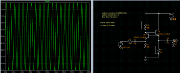
I am trying the schematic but i cannot make it work I used to fets at their place
I am getting absurd results (I am attaching a simulation)
Maybe the simplicity comes with other negative issues
I was struck by its originality and elegance
I am interested in simple circuits that can work as low gain line preamp and buffers using just one type of bjt NPN after reading this on the web
I understand i should look at "vintage" schematics like those dated around 1965 to 70 ?Why is NPN preferred over PNP?
Thus n-p-n is preferred as in this electrons have higher mobility than holes, which results in high mobility of energy. In a p-n-p transistor, the positive supply line becomes a common point of input and output current, due to which the ground current is positive. This is inconvenient for design and maintenance
Attachments
Last edited:
The smart thing to do is sim the current source on itself to make sure that you have that working.
After that you can use them as a trusted part in an amplifier or buffer circuit.
Doing everything at the same time just wastes ypur time.
For instance, in your circuit, Q2 B-E is constant 0.6V, I don't think that works.
That has nothing to do with the current sources. Even if R3 and R4 are so different, one is almost surely wrong.
Do you understand how the current source works?
You look up the required Vgs for a certain current in the data sheet. Say the FET needs a 2V Vgs for 5mA Id.
That means the source resistor needs to drop 2V at 5mA making it 2V/5mA=400 Ohms.
Make a circuit that tests this to get that out of the way.
Jan
Attachments
Last edited:
Hi thank you very much for your kind support I go back to books These current sources are too difficult for me to understand
I go back to simpler schematics Kind regards gino

I go back to simpler schematics Kind regards gino
Gino, it is the most simple circuit you can think of!
Make an effort. You want to spend the rest of your life grasping around in the dark?
How can that be fun??
Look at the graph I posted above. Select your wanted current. Then find the Vgs that corresponds to it. Then using the simple ohm's law equation I posted to find the R. Done.
Draw it in LTspice, just the current source between supply and ground and measure the current. Adjust if needed.
Jan
The smart thing to do is sim the current source on itself to make sure that you have that working.
After that you can use them as a trusted part in an amplifier or buffer circuit.
Doing everything at the same time just wastes ypur time.
For instance, in your circuit, Q2 B-E is constant 0.6V, I don't think that works.
That has nothing to do with the current sources. Even if R3 and R4 are so different, one is almost surely wrong.
Do you understand how the current source works?
You look up the required Vgs for a certain current in the data sheet. Say the FET needs a 2V Vgs for 5mA Id.
That means the source resistor needs to drop 2V at 5mA making it 2V/5mA=400 Ohms.
Make a circuit that tests this to get that out of the way.
Jan
Hi you mean like this below
yes i can read 2.28 mA through the resistor to ground Is this what you suggest ?
I guess that i should look at the CR diodes datasheet to find the currents ?Gino, it is the most simple circuit you can think of!
Make an effort. You want to spend the rest of your life grasping around in the dark?
How can that be fun??
Look at the graph I posted above. Select your wanted current.
I am trying and i will report on the findings for sureThen find the Vgs that corresponds to it. Then using the simple ohm's law equation I posted to find the R. Done.
Draw it in LTspice, just the current source between supply and ground and measure the current. Adjust if needed.
Jan
Thank you so much again
hi do you mean it works with the selected resistors ? i will check soon and thank you sincerely
First i would like to try with fets used as current sources
Well firts i have to understand the wanted currents
Thanks again I followed your schematic but used two BC546B and got this
2.28mA through 400 ohms is 912mV; do you see that the 912mV is the Vgs of the FET?Hi you mean like this below
View attachment 1321170
yes i can read 2.28 mA through the resistor to ground Is this what you suggest ?
I guess that i should look at the CR diodes datasheet to find the currents ?
I am trying and i will report on the findings for sure
Thank you so much again
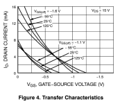
So the data sheet should say that for 2.28mA current the Vgs should be about 1V. Let's check that.
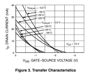
If you look in the data sheet, there are a few graphs for Id versus Vgs, for different FETs because they come in different Vgs(off) values, that's just because they can't produce them all at the same value (hence also the need for matching if you want two the same).
Fig 3 for a FET with a Vgs(off) of about -2V seems to show about 2.5mA at -1V. So that's pretty close to what you get.
Congratulations - your first current source.
Now back to your amplifier circuit. You need to know or decide what values these current sources need to have, and then check that in your test circuit looking at the data sheet.
Jan
Attachments
Thank you very much indeed for your extremely kind support and above all immense patience 🙂
I think i said that i am slow At school at math i was like 6/10 My syster was 9/10 but likes gardening
To be honest without a SW that makes all the calculations for me i could not even start
And without the precious help of Mr Mooly who passed me very good settings i was getting bad graphs
I would be just satisfied one day to understand how to choose the settings for the various analysis
I should take a LTSpice class one day These sim SWs fascinate me immensely They predict
I understand that the theory should always come first A competent designer at least should understand at a glance if a circuit can work or not
That saves a lot of work
Hi just last question I am using a lot this component labelled CURRENT in simulation

I am finding it very useful to find suitable working points
to replace it with actual components should i use a combination like this ?

any other solution ?
I am finding it very useful to find suitable working points
to replace it with actual components should i use a combination like this ?
any other solution ?
Hi thank you so much for the very kind and helpful advice Now the problem is to choose the way that could provide a decent result without adding too much complexity. The fet plus resistor is quite handy I will study the BJT current source immediately I guess that the CCDiodes could have limits ?
I do not think that they are in LTSpice default library I have problems even with adding models But i guess that those present by default should be more than enough for some basic exercise I have already simed some commercial circuits using different parts and the results are interesting
Next step would be to take a generic schematic and try to set values I am quite sure i will fail But i will try anyway
In the meantime i have found something https://sound-au.com/ism.htm
- Home
- Design & Build
- Parts
- CCL0130 and CCLH100 _ is there anything that can do the same job in a circuit ?