Transformer for F5 - 1 or 2 secondaries?

I need to order transformers for my F5. I planned to install two torodial transformers 320VA with one secondar 18V per trafo. Now I see that others are buying two transformers with two secondaries per trafo for dual mono and I don't understand why? What is the benefit of four secondaries instead of two?

Will 300VA 10A per channel be enough? I'm doing a custom order so suggestions are welcome

Greetings. Came across some Scan Speak Drivers, not sure what to do with them?

Kind of a long story. A golfing buddy of mine passed away - far too early. He was something of an audiophile and a packrat. His widow asked me to help clear out all his stuff. I ventured down to their basement and was amazed when I started looking in all the closets and boxes and bins of stuff. Hafner amps, Audeze headphones, etc. A lot of gear. I have spent a lot of time hooking gear up and making sure it works before trying to find a good home for all of it. Sold a bunch of stuff on ebay and raised a few thousand dollars for their Grandkid's college fund. His widow and I agreed that we did not want this stuff ending up in a landfill. My latest find is eight 5" Scan Speak 13M/8636-00 and four 8" Scan Speak 21W/8554-00's. They were packed carefully but not in their original boxes. They look brand new. I can hook them up and make sure they work, but would be surprised if they don't. So the questions is, short of embarking on a speaker build project (which I am considering), what do I do with them? What are they worth? If I were to sell, I would want them to go to someone who would build some speakers and enjoy them. I am going to do some research, but this site seemed like a good space to get some input. Thank you.

Elementary Noob Question of the Day: How tightly should you pack wool in an enclosure?

How tightly should I be packing wool into my enclosure?
I have this R15 cut in half (approx 2") and stapled to all the sides of the enclosure. I am leaving area behind the woofer to the port open with no packing material between those two.

I started packing in wool everywhere else inside the enclosure and quickly realized that I can lightly stuff it in there or I can jam it in there and fit 10x times as much inside.

I assume there is a happy medium here....? Should it just not be compressed further than how it comes out of the package? Should it be fluffed beyond how compressed it comes (I feel like it comes pretty tightly packed as it)

Attachments

  • PXL_20240711_133145418.jpg
    PXL_20240711_133145418.jpg
    385.4 KB · Views: 77
  • PXL_20240711_133146860.jpg
    PXL_20240711_133146860.jpg
    322.8 KB · Views: 76
  • PXL_20240711_133152800.jpg
    PXL_20240711_133152800.jpg
    426.4 KB · Views: 77
  • PXL_20240711_133154503.jpg
    PXL_20240711_133154503.jpg
    324.7 KB · Views: 78

I couldn't find the Target Function for this design

I'm experimenting simulating the conversion of 3 ways to 3.5 ways speakers. The objective of this experiment is to arrange the FR in a concept of integrated subwoofer speakers. I started by having a 3 ways speakers with typical 3 drivers; one tweeter, one midrange, and one woofer. Then, I'm going to add a second woofer to the system where the second woofer has its own cabinet.

The problem is I don't know the Target Function of the 3.5 ways speakers since I've never seen it before. I don't know what the ideal FR of the goal should be. So, I'd like to ask experts here for the criteria that would be recommended.

However, I have randomly tweaked the circuit myself. For the 3.5 ways conversion, I doubled the value of the inductor and halved the capacitor of the first stage crossover, and, doubled the second stage inductor again referred to the first stage.

Here is the original 3 ways system:
original 3 ways.png


Here is the modified 3.5 ways:
modified to 3.5 ways.png


Here is the simulated impedance plots of the two cases for comparison; blue dotted line = 3 ways, black solid line = 3.5 ways:
Impedance.png


I'm quite uncertain if it would work. Therefore, please advice me whether I did it correct or not.

PS. I know it should be done using actual measurements, but this is for research purposes.

Audiostatic ESH100 bias measurement

A few years back I bought a pair of Adiostatic ESH100 speakers. A hybrid set of a conventional woofer for the low end and an electrostatic panel for the mid a high spectrum. I did a restoration job, you know reglueing and refoiling the electrostatic panels and fresh paint. When I powered them up I was really satisfied with the result achieved.
But in longer listening sessions I found out that one of the stats was somewhat lower in volume than the other one. Forum member mattstat provided me kindly with several very useful hints. One of them was his advice to check the bias supply. Because life stood in the way it took me a year to pay attention to the audiostatics again.

I diy'ed this simple bias measurement tool (picture). A 1 Gohm hv resistor in series with a 1 Mohm one and double isolation. I don't expect exact measurements but for comparing and adjusting bias voltages it should be okay.

I couldn't find schematics of the ESH100 instead I found one of the ESH50 (picture). I also supplied several pictures of the inside and the electronics of the ESH100.

The transformer in picture 2 is the only one in this speaker.
Brown and blue wire at the left in picture 3 is 220V power.
Black wire with red tape in pic 3 is hv to foil.
Blue and red wire in this picture (top right) are connected to woofer filter.
The two black wires at the bottom of the pcb are connected to the stators. In the last picture it is easier to see that there are two black wires.

My question: to prevent doing something stupid I would like to know how and where to measure bias. For instance where to attach the ground clip of my hv probe ? Should I measure with or without connected esl panel ?

Attachments

  • es50_schem.pdf
    es50_schem.pdf
    39 KB · Views: 188
  • LD_IMG_2229.JPG
    LD_IMG_2229.JPG
    195.5 KB · Views: 304
  • LIMG_2386.jpg
    LIMG_2386.jpg
    122.5 KB · Views: 306
  • LIMG_2387.jpg
    LIMG_2387.jpg
    110.6 KB · Views: 306
  • LIMG_2394.jpg
    LIMG_2394.jpg
    89.3 KB · Views: 310
  • LIMG_2391.jpg
    LIMG_2391.jpg
    124.7 KB · Views: 299
  • LIMG_2388.jpg
    LIMG_2388.jpg
    110 KB · Views: 202

Fisher 400 and 500B Amps

The Fisher 400 and 500B (not 500C) are the most interesting amp I heard. They sorely need upgrade to Russian K40Y-9 caps including the tone controls and the one per channel damn ceramic cap in the audio chain. These amps (receivers) are far from the most clear sounding even after the upgrade, but the most pleasing amp on Rock & Roll. Live recordings are not placing you in the first 6 rows of seats, but at the 20th seat or so from the stage. The reverberation is just outstanding. You cannot hear this well on a stock Fisher 400 or 500 receiver. For some reason I am just mesmerized by the sound of these amps on rock and roll. They sound good with cheap Chinese 12AX7WA too.. I owned about 30 rebuilt vintage amps, none play as pleasing as these Fishers. Not for classical music, but best on hard Rock & Roll. Scott makes cleaner sounding amps, but not a Fisher My 2 cents.

Do I miss something in my crossover here?

Hi guys. I am new to speaker building. After doing some reading here and there, I decided it’s time to start making my first speakers.

My plan is to make a 2 way speaker, 1 tweeter and one midrange. I picked the drivers and designed my crossover with the knowledge I have. The SPL is traced from seller spec sheet. I am not ready for measuring equipment yet. I think it looks alright. Anyway, I am not sure if I miss something important.

Can someone share me some thought here? I understand I will need to tune it down the way. I’m just afraid I make some mistake that ruin everything from the start.

Thank you.

IMG_2226.jpeg

Building a center channel to match SRX812Ps

Hello -- I am Seth -- I posted this already in the new members area, but I don't think that's the right area for this -- I have an unconventional home setup (using JBL Pro speakers).

My man lair serves a triple purpose -- gym area, desk area, "theater" area. In the cinema portion, I have two PRX712s (which will eventually be SRX812P) and two SRX828Sps underneath for thumping (and boy, do the thumpers in Dune sound thumperin').

Basically, I'd like opinions on a center channel -- I'm still learning how all of this works -- but, I was hoping to be able to replicate the SRX812Ps. Basically, take the 2432H compression driver and sandwich it between two 2272F 12" drivers. A bigger box to compensate the additional woofer, and bam, massive center channel for my massive LRs. Basically a PRX825 but with 12" drivers on either side. (Don't ask me about side and back surrounds yet -- I have no idea what to try there)

But, yeah, I'll post in the appropriate forum for advice -- but feel free to comment here if you'd like.

(I've also considered going the way of a VTX V style design -- I'm still looking for ideas.)

What I'm hoping my equipment list will be in the end:
-SRX812Ps for LR (currently PRX712s)
-SRX828SPs for front subwoofers (there's not room for them anywhere else to even check if they sound better -- but that's alright -- they sound pretty great so far)
-Denon x3800H (coming tomorrow)
-Some bluray player -- most likely the mid-level Panasonic ($400 pricepoint, whichever that is)
-Sony X90L 65" (will be getting soon)
-Custom center channel to match LR
-Side and back surrounds (eventually)
-Possibly a 24" HS24 subwoofer for below 35hz -- we'll see . . .

Image: And yes, I know r/tvtoohigh or whatever -- the tv mount was here when we bought the house -- haven't moved it, don't know if I'll have space to move it, we'll see.

manlair.jpg

FS : VZaudio NS OPS Amplifier with two different IPS

Hi,

For sale I have a completed amplifier. It is the VZaudio NS OPS with the Tubsumo IPS and the Vertical CFA IPS.
Complete amplifier not available anymore, but all modules are still available

The amplifier was build with lots of care, lots of smd which are all soldered nicely. Along with this, you have the full control protection and startup board V6. It has speaker protection, soft start, over current, temperature control, etc... 1000VA Toroidy transformer.
Chassis, transformer and all other components, except for modules are not available anymore

You can get the information from the web site here:
Virtual Zero Audio Store

For the complete amplifier, I'd like to get $USD, but I'm willing to sell it in parts due to the shipping cost of such an heavy chassis (Heavily modified Modushop 5U 500mm).
This option not offered anymore

If you want to purchase everything except chassis and transformers, I would let it go for 500$USD
New and final price 300$USD for all modules only

I would also accept trades/partial trades for the following items :
Denafrips Ares II DAC
Schiit Gungnir DAC (with Gen 5 USB)
Troels Gravesen CNO-GRANDE drivers and crossover set

Shipping price will be priced according to your location and option chosen. Paypal is 4% extra...

Thanks
Do

Transformer replacement in AKAI 4000DS MKII

Hello there!

I've been visiting this community for some time now, but this is the first time I've ever needed to post, so allow me to introduce myself briefly. I work as a guitar tech in Spain and I record and produce my own music. I recently acquired an Akai 4000DS MKII reel to reel that I plan to use in my production chain, add color to certain tracks, echo, mastering and even some live recordings. I know this deck is not quite there at the HIFI spectrum, but that's why I got it.

I'm still waiting for it to arrive, but I'm already preparing the mod. It's an american 120V 60Hz unit, but we use 220V 50Hz in Spain. I could use a step down transformer but they're pricey and too big. The smaller adapter plugs seem very sketchy to me and I just don't trust them. To me, it makes more sense to convert the unit itself, it will only be used in Spain (or Europe if I ever sell it).

I have experience repairing and modding simple electronics, but it's not my area of expertise, so I'd rather just ask. I looked at the schematics and it seems to me that the only difference between models is the powerboard, which basically has only different transformer. There's a scrapper around here that will sell me an original european transformer for cheap. My question is, do I need to replace anything else in the deck or will it work fine if I just swap one transformer for the other?

In this schematic, down to the left the transformer my unit has (TI LET-19), and to the right of it, the transformer I'd need (TI LET-17). It looks like everything else is pretty much the same, except maybe having to replace the fuses and remove the little cap following the power cord? Any insight would be greatly appreciated!

Captura de pantalla (52).png


In any case, will keep you posted with the progress of the mod and will add pics in just so if in the future has this same issue, they have an easy page to refer to.
Thanks a lot!

Troubleshooting/repairing Fostex 6301B Amplifier?

Hello all, hoping someone with more electronics knowledge can help me with this issue and little project.
I have a pair of these Fostex 6301 monitors and use them as secondary/reference monitors for mixing music. A while back I replaced the deteriorating old drivers with the modern equivalents from Fostex. While not the fanciest thing, I do like them, their small footprint, simplicity of use, and single driver design.

One of them is giving me trouble, however. It powers up fine, but after playing for a minute or two, loud peaks in the music cause it to distort. If something is loud enough, it will distort and then stop outputting at all. The unit stays on with its power light, and if I wait a while or turn it off and back on later, it will play again and repeat the same behavior.

Any idea what might be going on here? I sadly don't have a schematic, and there appears to be many revisions of these under the same name.
Here are some photos of the speaker and it's insides. I assume the amp board must be rather simple - perhaps simple enough to fix?
Any input is appreciated! Thanks ahead of time.

Attachments

  • pA9IG7b.jpeg
    pA9IG7b.jpeg
    540.1 KB · Views: 115
  • 1p5DiEJ.jpeg
    1p5DiEJ.jpeg
    349.5 KB · Views: 108
  • 6r7Rf0d.jpeg
    6r7Rf0d.jpeg
    415.2 KB · Views: 101
  • FZC37QA.jpeg
    FZC37QA.jpeg
    352.2 KB · Views: 105
  • XO43A9a.jpeg
    XO43A9a.jpeg
    253.5 KB · Views: 119

B•I•C Venturi Formula 1 modifications and measurements

I have been playing around with these in an effort to make them listenable. I mod podged the old paper cones and it made a huge difference in the sound, (for the better). Now I'm working on the crossovers. I'm trying to tame the peaks at 2-3khz. I added an inductor to the woofer and I think my next step is to add a capacitor across the woofer. Any suggestions or insights are welcome.

Attachments

  • bic f1 1st spl.jpg
    bic f1 1st spl.jpg
    157.9 KB · Views: 71
  • bic f1 1st dist.jpg
    bic f1 1st dist.jpg
    122.3 KB · Views: 62
  • bic f1 1st wf.jpg
    bic f1 1st wf.jpg
    187.8 KB · Views: 67
  • 20240710_115321.jpg
    20240710_115321.jpg
    218.9 KB · Views: 72
  • 20240710_233957.jpg
    20240710_233957.jpg
    358.5 KB · Views: 67

For Sale SB Acoustics / Vifa Tweeters / Visaton Waveguide / Mission (SEAS) Woofers with Free Shipping

I have the following Speaker Enclosures, Woofers, Tweeters and Waveguides:

MINT Pair of Bookshelf Maple ENCLOSURES only (no drivers)-Dynaudio Audience 42W (with crossovers / terminals / foam insulation / ports & grills) available for $109 USD shipped to Canada & US

2 Dynaudio 15W75 6" Woofers with 3" diameter voice-coils (from Dynaudio Audience 42W speakers)
SOLD

SOLD to Reid Dynaudio D28/2 1" Soft Dome tweeters (from Dynaudio Audience 42W speakers SOLD to Reid

SOLD to David
2 NEW SB Acoustics SB26STWGC-4 1" Soft Dome (with integral 4" Diameter Cast Aluminum Waveguide) Tweeters
Waveguide is constructed with a stable 1/4" ( 6mm) thick waveguide / mounting plate
SOLD to David

2 USED Peerless D27TG35-06 1" Soft Dome Tweeters
SOLD to Ron

2 NEW Visaton WG148R 6" Waveguides (for 104mm faceplate tweeters like the Peerless tweeter above)
SOLD to Chris

1 (qty) Mission "Super 770" - SEAS P21WO-11 8" Woofer
1 (qty) Mission "Argonaut 1F II" - SEAS P21WN-15 8" Woofer
2 (qty) Mission 770 Woofer Trim Rings
$69 USD for Pair c/w Trim Rings with Free Shipping in US & Canada (qty)

Boston Acoustics 8" DVC (Sub) Woofer
$29 USD for Single with Free Shipping in US & Canada


5173477-d8dace80-speaker-drivers-new-used-tweeters-waveguides.jpg5173478-b0569796-speaker-drivers-new-used-tweeters-waveguides.jpg5173479-df6407eb-speaker-drivers-new-used-tweeters-waveguides.jpg5173480-ac827f70-speaker-drivers-new-used-tweeters-waveguides.jpg5173484-ed387b21-speaker-drivers-new-used-tweeters-waveguides.jpg5173505-e78715f6-speaker-drivers-new-used-tweeters-waveguides.jpg5173506-bd3bf5a7-speaker-drivers-new-used-tweeters-waveguides.jpg1000006089.jpg1000006092.jpg20240707_192042.jpg

BK Electronics mosFET 100 watt modules

Hi Guys
New on here. Just bit of advice as I don't know much about builds of op amps. I got this pair which are in pretty good nick and have used a good old spare chassis I had lying around to mount these in.

Now am I right that the heat sinks don't need earthing. I've earthed the j50 and k135s all powered up okay and I'm getting 47.5v on main rails. Not measured anything else yet just letting them burn in for a bit.

I now need to mount the pots which I think are 47k? And obviously put in the output input XLR sockets in. I have a spare set of old led lights for the on off switch but was wondering if I could run them from the vu meter points +12v put in a shunt resistor to get voltages down. Not sure what rating they are? Need to work that out.

I also have a decent fan but it's 115vac so need to work out how to get that working as I also have a pair of heat sensors you mount onto the heatsinks so think I'mgonna need to build a module to get that working with right voltage rating or just buy a 240v fan. But I'd rather use what I have if possible. So quite a bit to do yet. But I'd like to get it right and not blow it up.

When I got these they where mounted in a homemade chassis but it was a mess and everything in there apart from the modules had all been sprayed black including the wiring. The pots where covered in gather tape and on switch on you could not turn the volume down it was like it was just set at a level. You could increase volume. So is this normal or was it wired up wrong? Again wires connected together using a bit of solder and insulation tape. Hence moved into a decent chassis.

Anyhow any feedback welcome.

Cheers

For Sale Opportunity for an Enthusiastic DIY Audio Kits Builder

For clearance, I am offering the following diyaudio PCBs and various component parts to an interested individual with kits building experience and a desire to sell diy audio/electronic projects and components online.

The lot offer includes the following:

  • 300+ pcs. PCBs for a 260W Stereo Power Amp.
  • 450+ pcs. PCBs for a 120W Hafler compatible Amp.
  • Lot of Various populated power amp. modules (not tested)
  • Lot of Power and small transistors
  • Lots of IC chips, diodes
  • Lots of various resistors
  • Lots of large and small capacitors
  • Various power transformers
  • Lots of heat sinks
  • Many other associated component parts
  • Some variable power supply kits and electronic items
The original lot costs are over thousands and thousands of dollars. I am offering to the right person at a big loss price. Any of your reasonable offer is welcome. Due to the size and weight of the entire lot, I am not in favor of selling overseas as the shipping cost will be very high. I would prefer local pickup in the area of Markham, Ontario, Canada. If interested ask for address to drop in take a look.

Attachments

  • DSCN0131.JPG
    DSCN0131.JPG
    75.9 KB · Views: 96
  • DSCN0134.JPG
    DSCN0134.JPG
    68.5 KB · Views: 92
  • DSCN0135.JPG
    DSCN0135.JPG
    72.7 KB · Views: 85
  • DSCN0136.JPG
    DSCN0136.JPG
    72.3 KB · Views: 82
  • DSCN0137.JPG
    DSCN0137.JPG
    72.5 KB · Views: 80
  • DSCN0138.JPG
    DSCN0138.JPG
    66.8 KB · Views: 89
  • DSCN0139.JPG
    DSCN0139.JPG
    63.2 KB · Views: 91
  • IMG_20200613_181600.jpg
    IMG_20200613_181600.jpg
    351.4 KB · Views: 87
  • IMG_20200613_181618.jpg
    IMG_20200613_181618.jpg
    195.5 KB · Views: 92

Operational amplifiers and feedback loop : low pass decoupling capacitor : which frequency ?

Hello,

I'd like to know, when using an operational amplifier in a transimpedance conf. for a current output dac chip, what the best strategy to choose the value of the feedback resistor decoupling cap.

Assuming this cap is used for stability of a high bandwith OPA (> 50 Mhz or >100 M hz for illustration), how would you choose the low passmade by this capacitor ?

  • maximum flat : what is shown in datasheet at 0.1% flat low passs
  • something in the kilo hz instead as a 6db filter for the NOS DAC : illustration 30 K hz
  • 200 K hz (I often this number in conversations)
  • no feedback capacitor but a passive RC low pass before the next stage (buffer) ?

Is the phase angle an important item in that choice ?

I readed high frequency bandwidth was something important for amps, is it too for I/V stage of a current output DAC chip as well or better at the opposite not to play too much high, mostly if using NOS DAC with no reconstruction filter at the output to avoid nasties to come back in the audio band ?

Should be filtered both with the I/V operational amplifier, then in the next operational amplifier used as buffer for instance ?

Thanks

The "Unorthodox and Affordable" System 4 Years Later

This is an update of my "unorthodox and affordable" system ( https://www.diyaudio.com/community/threads/an-unorthodox-and-affordable-1st-class-system.357779/), though this is condensed to highlight the system as it stands today. The description, like the system itself, has been simplified which is always a good idea. Besides realism, the mission statement continues to be (a) getting as much of the audible band as possible to play through the ideal driver form, and (b) eliminating phase shift from source material entry to loudspeaker entry.

Re-edited continually with latest info. New info here is again an update of xover points

1. Overview

a. Speakers

Loudspeakers are as follow.

Subwoofer (1): This has not changed from 2020. A Peavey 18" Pro Rider is mounted in a Seismic Audio 18" downfiring (about 20* from vertical) sub cabinet with internal crossover bypassed.
Woofer (2): Also unchanged; each woofer consists of a vintage Altec 421A mounted in a Seismic Audio 15" slot-loaded cabinet, again with internal crossovers bypassed.
Midrange (2): Each mid is an Atlas DR-72 re-entrant horn loading an Atlas PD60A driver. The horn has a very long 61" path length and a big 30" diameter round mouth, enabling a very low horn cutoff. Rope caulk is used on the exterior to damp ringing.
Tweeter (2): The very affordable (~$30) Dayton D40T driver, which was modified by bypassing the transformer, is loaded by a DS18 PRO-H110 exponential horn with a 5.43" diamater mouth and a roughly 6.43" path length. Like the mid horn it was chosen to load the driver effectively to a low range. Like the mid horn it is damped with rope caulk. Its near-0 price belies its performance. And the D40T has been enough of an eyeopener that I have replaced my Atlas PD5VH with it. It has me taking a 2nd look at all Dayton equipment.
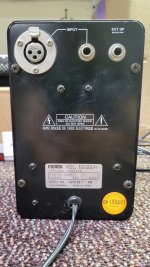
Supertweeter (2): My Beston RT002a ribbon tweeters have been replaced by a pair of Fostex 025h27. Despite the excellent performance of the Bestons, I was forced to cross over higher than I liked so I decided to give the Fostex tweeters, lying around for a couple of years, a shot. Despite the fact that they needed more equalization than the ribbons (which needed almost none) they permitted me to drop the xover point by about 2khz, and I am tickled with their resonant frequency (1.9khz) being another 2k or so below the range for which I use them.

b. Power Amplification

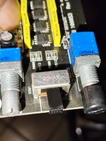
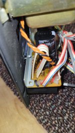
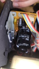
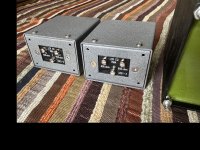
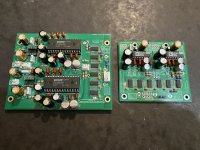
As before, the speakers are driven by class-T chip amps. Two 1U 19-inch industrial surplus rack mount boxes each house two Sure AA-AB32971 stereo boards and a switching power supply, each input run through a noninductive potentiometer for attenuation and tuning of input impedance. I have compared their specs to those of the initial generation of GaN boards and find them to be at least as good; e.g. the switching frequency is 770khz compares to the GaNs being generally spec'd around 800khz. Distortion figures are at least as good, dead time or no dead time. I'll check back on GaN in a few years.

c. Crossover

The crossover is 'housed' in a refurbished HP 8300 Elite with Intel I7-3770 4-core by 8-thread processor (running Win11 up-to-date) supplied with a simple Vantec PCIe 7.1 sound card (CMedia 8828 chip set), used for both its optical input and multichannel analog output. Driver is provided by MS.

d. Front End

The front end, another HP desktop, is used to stream external sources and play recorded sources off a fast NVME SSD. The machine lacks M2 boot capability so the disk is mounted in a PCIe caddy for music storage. An Xonar 5.1 PCIe soundcard (CMedia 6620a chipset) is used only for its optical SPDIF output; the output is converted to coax (my data link to the crossover computer requires coax input and is mounted high, requiring a ~20' cable thus making coax preferable anyway). The original machine, identical to the crossover machine, was rendered inoperative (somehow) by an ISO windows update and has been replaced by another, an HP Prodesk with Intel I5-4590. Expansion cards were transferred to this 4 core 4 thread machine. I detect no issue. Thankfully I had the foobar configuration files (in 'roaming') backed up on a USB disk by a timer-driven batch file script.

e. Data Link (optical cable substitute)

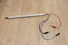
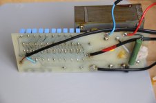
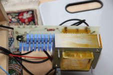
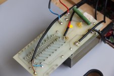
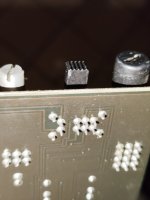
SPDIF stereo is sent from the front end to the crossover machine via optical means. It consists of a simple 74HC04-based optical-to-coax converter (with a faster 74AC04 hex inverter substituted) which, via a cable-grade 20' cable, connects to a second converter. PCIE-based soundcards with coax SPDIF are getting hard to find, necessitating the 2 converters. The second converter, coax-to-optical, also has the 74AC04 substitution and is modified to drive a 6mm 650-nm laser module instead of the Toslink output module. The laser is aimed at the open end of an optical cable connected to the Vantec optical input on the crossover machine, some 40' away. It is a superior alternative to a long optical cable. I do not know its upper limit, though I have in the past verified 384k.

2. System Setup

a. Front End Machine

The purpose of the front end computer is to supply source material, process it and send it to the outside world as an SPDIF stereo signal. Foobar2000 v2 (32 bit) is the vehicle of choice. Source material is stored as mentioned above, except for that which is directly streamed from the web. Downloads, CDs etc. are converted to FLAC for storage. The DSP stack contains these plugins, in order:

i. Foobar's 'amplify' level control cuts input signal level by ~18dB to ensure no clipping in the signal processing chain.
ii. Sox resampler upsamples to 192k for all further processing.
iii. Foobar's 'set sample rate' declares 192k here. This may be unnecessary but since I don't know, it's there.
iv. Reaxcomp, a compressor, is configured as a 18-band expander to enhance/restore dynamics. The ideal would be of course one band per frequency, which is impossible, but division into bands minimizes the dependence of a high frequency's expansion on a much lower frequency's level (since the former rides on the latter). The compression ratio is 0.88:1, which is about 1.14:1 expansion.
v. Two instances of Foobar "Convolver" apply equalization from curves built in RePhase as phase-linear FIRs at 192k samplerate and 256k (as a power of 2) taps. In the first engine two curves are used, the first to apply amplitude correction for the slightly nonflat response curve from Reaxcomp and the second a phase-correction curve for the phase shift induced by Reaxcomp, which can be measured by several VST test tools. The second engine is for application of a loudness contour curve.
vi. A second 'amplify' instance may be put here if I want to boost the level.

The output stage is WASAPI push (the Xonar card doesn't like 'event' for some reason) with copious buffering as latency is not a big concern for me. Driver is set to 192k 24 bit and exclusive mode.

b. Crossover Machine

Here, the Vantec 7.1 PCIe card with CM8828 chipset is used, acting as default input on its optical-in and as default multichannel output on the 7.1 (analog) outs. The driver is configured for 7.1 surround with full range on all outputs (again exclusive mode), thus an 8-channel output card, perfect for a 5-way crossover with a single sub and paralleled woofers. Foobar2000 output is configured to WASAPI event. I suggest trying this practically free all-in-one PCIE output solution before you spend a lot on hi-end DACs etc.

The DSP stack of Foobar2000 is as follows, in order:

i. 'set sample rate' is set to 192k.
ii. The major plugin, ConvolverVST, provides 2 to 8 channel multiplexing, 10 filters to 8 active outputs. In addition, the config text file for ConvolverVST also specifies per-channel delay times to align the drivers (and compensate for differing latencies among the filters should that occur; see below), and a number of other useful parameters. Also, I use 8 partitions and 'patient' optimization, which are set in the small GUI interface of ConvolverVST. I have not found an alternative that does as much or performs as well. Major notes on usage are in the original post. Each filter file includes (besides the filter itself) a driver-specific phase curve to precorrect measured phase shift at the loaded amp output, and (for mid, hi, and super units) an amplitude curve overlaid onto the filter which is the inverse of the published amplitude response of the driver.

The addition of the two supertweeters was accomplished using my 8 available outputs (and amps) by paralleling the woofers onto one mono channel which, with a 150-hz low-pass, is indistinguishable from stereo anyway, and the long wavelength of 150hz obviates any noticeable parallactic smear. That left me with 2 outputs for stereo supertweeters (the single sub also taking up just one mono channel). The config file for Convolver VST was modified with 10 input filter entries demultiplexed down to my available 8 outputs. Note that the spec for input/output channel number remains at 2/8, with the delay list still having 8 entries (the number of physical outputs). You can specify any number of filters in the list (in this case 10, L/R for each of the 5 frequency ranges, with outputs directed to the 8 available outputs by downmixing each of the woofer outputs to the single mono output channel; same for the sub.

iii. Next is Matrix Mixer, a convenient multichannel level control that works well to balance output levels for varying reasons.

iv. Foobar's 'amplify' may be used to further modify (increase) level on output as most processing is held at low levels to prevent clipping on the DSP stack (the only place I have ever observed clipping). It handles multichannel.

3. Other Stuff

a. The choice of crossover frequencies and filter parameters is based on what sounds best but also tries to give consideration to a few axioms:

i. The lowest frequency asked of a horn should not have a wavelength that exceeds the path length of the horn. Call this 'full wave' loading. I find that half-wave loading is fine and try not to exceed that. It gives me another octave.

ii. The lowest frequency asked of a horn should have a wavelength that does not exceed the circumference of the (round) horn. If your horn is not round, compute its mouth area and calculate the circumference of a round horn of equal area.

iii. No horn should be asked to provide more that 3 octaves. I observe this limit on the mid and hi-mid horns. I take the mouth area ("circumference = lowest wavelength" rule) as the reference frequency.

iv. Beranek's horn equations provide an in-depth characterization of a horn, but also tend toward full-wave loading and may be too restrictive.

Back to the crossovers. They are Linkwitz-Riley filters set as steeply as possible with a parameter of 996 (a 166th order filter, approximating a brickwall). Windowing is Albrecht 11-term.

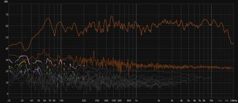
The crossover points are
Sub/Bass: f=65.
Bass/Mid: f=150.
Mid-Hi: f=850.
Hi-Super: f=3400.

I have tried to observe half-wave loading for the horns (the DS18 horn goes into quarter-wave loading at 1050hz, so half wave is violated, but the big driver doesn't seem to care). I take the base frequency of the big horns at 143hz, the limit dictated by a 30" mouth diameter (they are still within 1/2-wave loading at this point). This gives a 3-octave limit of 1144hz, which as seen is observed. I got my large horns in hopes of lowering the hi-pass point as much as possible; I never dreamed I could get it cleanly down to 150hz.

I chose the DS18 HF horns because I saw an unusually long path length for a tweeter in the photos. They have proven excellent, The mouth size predicts a 794hz low end before loss of control, thus they should pass 3 octaves at 6352hz, well above the low-pass currently in use.

The Fostex horns are running well within their limits for path length and mouth size.

I found that the filter latency may differ for different bands if 'energy' centering is chosen, so be sure to note all latencies shown in RePhase upon filter generation if you use that centering format. You will not only have to add delay(s) to the filters for appropriate physical alignment ("absolute phase") but also augment them with compensation for differing filter latencies should they occur. However, use of 'middle' centering (perhaps the better option anyway) seems to obviate this issue, with latency apparently dependent only on the number of taps and/or sample rate, which will be the same for all bands.

b. The "Foo_record" plugin permits Foobar to play the default sound input (in this case the optical input of the Vantec). Its playlist entry is set using 'add location' and entering "record://". This will read the default input, set in MS audio config.

c. A word on running foobar2000: Since I have multiple processors on each machine, I start Foobar with a batch file that specifies priority and affinity in the 'start' command. Priority is set at Realtime. To get that you must right-click your batch file icon and confirm administrative privilege since MS wants to be sure you know what you are asking (if you simply double-click your batch icon MS will default you to High priority). The magic trick is that I also set affinity to run Foobar only on the last half of the processor set (hex F0 on the crossover machine with 8 threads, hex C on the front end with 4 threads). I've been running this way without incident for a long time so if you have enough processors you are highly unlikely to "brick" even a fully-functional machine, which mine are (they are also backed up with Macrium, and the ever-expanding music collection plus the foobar directories are backed up directly as files each few days using a batch script). Some adjustments to foobar will be required for Realtime; e.g. do NOT use MMCSS on WASAPI; it will prevent the spun-off WASAPI process from inheriting Realtime priority and things won't sound pretty.

d. Foobar2000, up-to-date, is run in its longtime 32-bit format. With the advent of version 2, a 64 bit format is also available, but it will be some time before the various plugins are available in 64 bits, and some of my VSTs (which are critical) may never be. When/if I find that I can smoothly incorporate my 32-bit plugins to the 64-bit version I may switch to it. Or not. I firmly prefer the old VST adapter version 2.4 over the new adapter, which reinstantiates itself as a process every time a signal appears, in my case creating latency that even I can't tolerate. Moreover, despite inheriting affinity from the parent process, it fails to inherit priority(?), at least according to task manager.

e. A note on Sox resampler: Under advanced preferences, its initialization parameters include the somewhat mysterious "Service Priority." Attempts to find an explanation have in the past not been helpful. I have found recently while playing "hi-def" music test recordings (those things can actually be useful sometimes) that setting it below its default of 100 (say ~90) resulted in a good deal of relatively quiet detail emerging in the music, telling me that it may be an actual thread priority. However, I was able to eliminate most of this effect by manipulating my 'push' buffer size in advanced/output, in this case making it smaller.


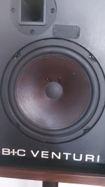
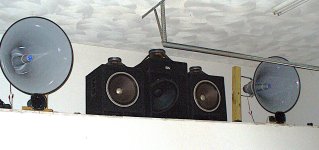
That's it in a nutshell. Here's a pic of the speakers. Note that the small horns don't show the D40T drivers, nor are the Fostex tweeters evident; I'll update the photo at some point.

spkrs_10_2024.JPG

Attachments

  • spkrs_7_11_24.JPG
    spkrs_7_11_24.JPG
    556.3 KB · Views: 115
  • Like
Reactions: Netlist

How can I watch a region 2/PAL DVD in the US?

I really want to watch a tv series, Charlie Jade, but it's no longer on streaming services and Amazon only has a dvd set that's region 2/PAL.

I was thinking I could hook up a usb dvd drive to a computer, rip it, and use some kind of conversion software, and copy to a usb stick? Then I could play it on my TV through a usb stick.

Or maybe somehow hook up the usb drive up directly to a roku or lg tv?

I really know very little about this stuff.

Philips CD304 won't read discs

Hello,
I've bought a faulty Philips cd304 to try to repair, but no luck so far.
The player starts up but won't read discs. Usually, the laser swing arm moves to the innermost position, tries to focus, the laser emits light, but the turntable motor doesn't move.
Sometimes when I turn it up the display just lights up all the lights and sometimes the swingarm moves to the out position and the motor spins, without any disc.
I've soldered the wire through all griplets, changed all the 33mF electrolytics on laser board and servo board, cleaned and lubed spindle and swingarm bearings, checked all the voltages from the power supply, tried adjusting the turntable height, the usual stuff I've found information about, still nothing.
I'm not sure what to do next, I didn't touch the power supply board because the voltages were ok, but maybe I should replace all the caps there?
Anyway, I'm new at repairing cd players and trying to learn, any suggestion on what to look for next would be greatly appreciated.

For Sale LCR phono kit

All NOS, set of:
  • pair of LCR modules
  • pair of interstage transformers
  • one choke.
LCR modules are from acoustic dimension (NL)
Transformers and choke are from polish manufacturer (IDHOS).
I assume all parameters are visible at the pictures.
Additional painting may be needed.

Price for this kit is 1,150.00 Euro plus shipping.
EU customers preffered.

Attachments

  • three-trafos.jpg
    three-trafos.jpg
    708.5 KB · Views: 86
  • lcr.jpg
    lcr.jpg
    625.3 KB · Views: 94

Moode Multiroom and BT: a better way?

Hi,

I want to be able to cast music/sound from my phone to several speakers throughout the house and move everywhere freely.

I saw that the latest Moode (9.0.4) allows for several "routers" to distribute BT to multiroom "clients" but as I understand it it would require (logically) require to stay within BT range of the first "router" we cast to.
Would it be possible to send sound from a phone (over IP) to a server that would use that input as a local web-radio? Could a Pi also do the same (with, say, sound from a record player)?

As I understood it WiiM would do the job, it's just that the price is steep.

For Sale Dynaudio Midbass & Tweeters with Free Shipping in US & Canada

1) MINT condition pair of Maple Audience 42W ENCLOSURES ONLY (No Drivers) can be shipped Free to US & Canada for a total of $109 USD.

2) *SOLD to Chris
- The single Good condition Rosewood Audience 122C Center channel can be shipped in ORIGINAL factory box for SOLD with Free Shipping to US & Canada.

OR buy drivers only as below:

1) 2 Dynaudio 15W75 6" Woofers Model 84405 (4 ohm) with 3" diameter voice-coils (from Dynaudio Audience 42W speakers)
$139 USD per pair with Free Shipping
SOLD to Vik

2) 2 Dynaudio D28/2 1" Soft Dome tweeters (from Dynaudio Audience 42W speakers)
SOLD to Reid

20240707_192042.jpg

Crossover questions

I own a set of Vandersteen 2Ce Signatures. I just purchased a Vandersteen Model 2W subwoofer on eBay. It has not yet arrived, but I’ve been doing some reading, and it appears that I will need a pair of in-line crossover between the preamp and the sub. Apparently Vandersteen supplied these with the product, but they are now scarce and expensive.

Apparently, the Vandersteen x-overs were variable according to the input impedance of the amplifier. This is confusing to me. Since the sub is self-powered, I would assume that any relationship between the sub's amplifier and the preamp should be handled without an external device. If the amplifier in question is the amp that is powering the main speakers, then I’m also confused – but I’m often wrong. (FWIW, the input impedance of my main amp (PSA BHK 250) is 50K single ended and 100K balanced.)

I happened to notice a set of line of in-line crossovers from Harrison Labs (https://www.hlabs.com/products/crossovers/). The only variable with them seems to be the crossover frequency - not the input impedance of any amp.

I wonder if these crossovers would meet my requirements. Any assistance would be greatly appreciated.
  • Like
Reactions: Amami Life

Still trying to understand the relationship between driver and cabinet volume

It may sound stupid but I still can't understand this relationship. If a driver requires 20 litres for optimal performance, under what circumstances does it need the volume: 3v, 20v?
Again, sounds stupid but due to the loose nature of air molecules isn't the an output level where the driver is not creating enough pressure to excite the port?
I ask because I have cabinets that sound excellent at low volumes but flatter to deceive & others that only sound good when driven hard?

Hello - Joined to create a very large center channel to match my LRs

Hello -- I am Seth -- and I have an unconventional home setup (using JBL Pro speakers).

My man lair serves a triple purpose -- gym area, desk area, "theater" area. In the cinema portion, I have two PRX712s (which will eventually be SRX812P) and two SRX828Sps underneath for thumping (and boy, do the thumpers in Dune sound awesome).

Basically, I'd like opinions on a center channel -- I'm still learning how all of this works -- but, I was hoping to be able to replicate the SRX812Ps. Basically, take the 2432H compression driver and sandwich it between two 2272F 12" drivers. A bigger box to compensate the additional woofer, and bam, massive center channel for my massive LRs. (Don't ask me about side and back surrounds yet -- I have no idea what to try there).

But, yeah, I'll post in the appropriate forum for advice -- but feel free to comment here if you'd like.

What I'm hoping my equipment list will be in the end:
-SRX812Ps for LR (currently PRX712s)
-SRX828SPs for front subwoofers (there's not room for them anywhere else to even check if they sound better -- but that's alright -- they sound pretty great so far)
-Denon x3800H (coming tomorrow)
-Some bluray player -- most likely the mid-level Panasonic ($400 pricepoint, whichever that is)
-Sony X90L 65" (will be getting soon)
-Custom center channel to match LR
-Side and back surrounds (eventually)
-Possibly a 24" HS24 subwoofer for below 35hz -- we'll see . . .

All about pre power amplifier DSP

Hello there,
I think I have lost a few years somewhere, and as a result, I am somewhat out-of-touch with DSP processing and its cost.
I thought it might be good for some members to learn more about it.
It would probably be good for 'posting' to start in a simple & basic way, then leading to more technical aspects.
I, myself look forward to some reading & thoughts. A question I have is:
Is DSP the future of audio alignment and 'perfection'?
  • Like
Reactions: Subuckethead

For Sale LME49710HA and LME49720HA, TO-99

LME49710HA and LME49713HA sold!!
LME49720HA is for now still available, limited quantity.
Regards.


National Semiconductor High End audio op-amps.. Those were around 10 USD when available, now already obsolete. Have a quite large stock, asking for 4 USD pc. Free shipping worldwide for more than 5 pcs.

https://www.pken.net/ish_mm/datasheet/ns/lme49710.pdf

Reagards

Attachments

  • DSC03155.jpg
    DSC03155.jpg
    370.5 KB · Views: 1,321

Two-Way Designs Incorporating FR?

This is a question mainly to Scott and Dave. I think I remember reading somewhere Scott that you were working on some 2-way designs incorporating FR drivers? Have you made any progress on these, I wonder?

Having built the triangle speakers using MAOP 7s and a home streamer using Alpair 6.2s I am looking for ideas for the next build, having hopefully built up enough confidence to make something with greater acoustic presence for the living room.

Ideally (but not fixed) I'd like a stand-mount solution for a 6m x 5m living room that gives "effortless bass" (if that's a term?) along with the silky-smooth mids and trebles of the MA drivers, hence the question about two-ways. I listen to a lot of electronic music (among other styles) and my first two DIY efforts reproduce this type of music politely rather than with excitement (compared to say my B&W 607s3s in the study).

I'd prefer not to use a separate sub-woofer, so would I be better off going for a conventional two-way using say SB or Scanspeak woofers and tweeters, or is there a WAW or 2-way design in the wings that might be worth waiting for? Even better if I can incorporate curves into it! My other equipment is a superb 25-year-old Lyngdorf-built Tact Millenium digital amplifier and a streamer (currently Bluesound 2i but to be upgraded). Current speakers in the lounge are floor-standing Dynaudio Contour 3.3s of a similar vintage to the amp, but I'm looking to build something with less bulk and more sparkle to get the best out of lossless streaming.

Hello

Hello! My name is Sam and I've been a long time lurker here on the forum. My hobbies include my home HiFi system which I built from the ground up with custom speakers, amplifiers, and DACs whos design was largely inspired by the many talented hobbyists and engineers that contribute to this forum. I am an active-crossover enthusiast and my long term goal in my audiophile journey is to design a fully active system that can rival the best passive systems.

Tubes for sale

GM-70 — 100 pcs.
5C4S — 100 pcs.
6N2P-EV — 268 pcs.
6N3P-E — 300 pcs.
6N6P — 1500 pcs.
6N6P «Foton» — 100 pcs.
6N8S «Foton» — 300 pcs.
6N13S — 100 pcs.
6N23P — 700 pcs.
6P3S «Foton» — 200 pcs.
6P3S-E — 50 pcs.
6P14P — 200 pcs.
6P14P-EV — 300 pcs.
6P14P-ER — 100 pcs.
6S2S — 100 pcs.
6S4S — 30 pcs.
6S15P — 50 pcs.
6S33S — 50 pcs.
6S33S-V — 100 pcs.
6S45P-E — 100 pcs.
6F3P — 200 pcs.

Super tweeter for HI RES

Good new year to everyone.
I have been learning about HI RES audio, and I have understood the influence that ultrasonic harmonics have on audible frequencies, making us appreciate details and subtleties that recordings have and that we would not otherwise appreciate.
I have also understood that for these ultrasonic harmonics to be present, they must be present from the recording, to the speakers, through the entire audio chain.
Thus, having speakers that are not suitable for HI RES, that is, they reach 20khz, I have thought about adding membrane super tweeters, which reach about 40khz.
Of course not adding it to the box of my speakers so as not to damage them, but rather in its own box superimposed on my speakers.
Would this be effective to transform my boxes into HI RES speakers?
Greetings

Question about Cornscala Active Crossover combined with Passive Crossover

I have a question on my Klipsch Cornscala, hybrid-speaker build. The Cornscalas are 3 way speakers with woofers at 96 db sensitivity, mids at 108 db to 115 db depending on the horn, and the tweeters at 107 db. If I run a solid state amp on the woofers without a passive crossover and a tube amp on the midrange and tweeters, matched together with a passive crossover, can I run a MiniDSP 2/4 HD between the woofer amp and midrange/tweeter amp, and boost the gain of the woofer amp to match the native sensitivity of the mids and highs running near their lowest native sensitivity of 107 db, rather than dropping them to 96 db to match the woofers native impedance with a passive 3 way x-over? Paul Klipsch was all about sensitivity, and it would make my little 6 watt tube amp seem much more powerful. Thanks in advance for any insight!

Hope this is the right place to post this. If not, please guide me to where it should go.

Boxing sensible circuitries (clocks, DAC, pre...) VS RF (EMC/EMI) : what is good enough ?

Hello,

At reading some papers about EMI/EMC, wonder if there were some good practice for boxing the sensibles circuitries of the topic question ?

A pcb has several plane plans, top and bottom of the cabinet are thick plans and hearted. Is that layout making bad behaviors as antennas for instance that can harm more than it shields (most of the time boxing is made of ferous material that acts as magnetic shield trap at some frequencies. But what about the next plane that is the pcb ? Antenna effect (stray capacitance that could arm ?

Is metal boxing automaticly better there than wood for instance ? Are there good practices but the expensive material for shielding. Ferous, Copper, Nickel sheets ? Are the EMC not a lost cause because anyway we have wires in and out from that cabinets ?

A little too much open questions, but you got the idea, I am looking for general directions to follow and to understand how important or good enough it is for such sensibles devices and when it becomes a no-subject for audio.

thanks
  • Like
Reactions: Sorenm

Bias issue

So working with brand new amplifier big and famous that had a customer complain about sound
initial test proved the amp was too cold
Checked bias according to the manufacturer and found low ....
Manufacturer need 8mv per transistor but found only 2.5
So adjusted bias and all appears to work fine .....
Placed a question to the chief engineer ( Turkish ) ( ?????? ) about it, since this is not only famous but also very expensive amp
And the answer was that may be from transportation trimmers have been moved Trimmers areBB top quality 10
bb multi.jpg
turn
Please comment your opinion for this bellow

Differential inputs - diff all the way to ADC or convert to SE?

I've been looking at the designs of some popular audio interfaces and I found that none of them contain in-amps (or even diff-amps) for their differential inputs. Instead they separately buffer the plus and minus inputs, route them through some analog switches and gain/attenuation circuitry, then to separate drivers for the differential ADC.

This was not the structure I expected! The ADC (CS4272) likes symmetric signals, so I'd rather have the input stage to immediately convert the diff inputs to single-ended with high CMRR instead of relying on the ADC. Sure, there's not much common-mode DC since the inputs are AC coupled with caps, but what about mains hum and other AC common-mode noise?

Is this for saving cost? Perhaps going diff->SE->diff would require 1-2 more op-amps.

Technics RSM-255X tape head source

I have an old Technics RSM 255X tape deck that works pretty good. I want to copy off some recordings I made with the dbx circuitry. It has some pretty outrageous hiss which may be due to the tape head wearing out, there is a definite groove on the surface. Does anyone know of a replacement or a source of parts. I could buy another on ebay but it probably has the same issue.

Substitute in Parasound 2SC3423-O or 2SC3423-Y and 2SA1360-O or 2SA1360-Y for unavailable 2SC3423/2SA1360 ?

I'm wanting to replace 2SC3423 and complimentary 2SA1360 in a Parasound input stage (with a somewhat random oscillatory symptom). They seem to no longer be available but 2SC3423-O, 2SC3423-Y are, as are

I've read this "The 2SC3423 transistor can have a current gain of 80 to 240. The gain of the 2SC3423-O will be in the range from 80 to 160, for the 2SC3423-Y it will be in the range from 120 to 240."

Similarly, I've read "The 2SA1360 transistor can have a current gain of 80 to 240. The gain of the 2SA1360-O will be in the range from 80 to 160, for the 2SA1360-Y it will be in the range from 120 to 240."

Would these be plug'n play substitutes? The target circuit is shown in the attached pic.
Should other substitutes be considered instead?

Attachments

  • HCA-2003 Front End.jpg
    HCA-2003 Front End.jpg
    190.6 KB · Views: 104

Hello from San Francisco

Hello,

I have worked in the hi-fi world for over six years now, and have performed and recorded music with samplers and synthesizers for closer to ten. Generally interested in all types of audio tech and good sound, although I was educated in the arts/humanities rather than engineering.

Maybe the first online forum I've joined ever. Happy to be part of what seems like a friendly and generous group.

Please take me to school on audible quality differences between capacitors, inductors, and resistors

As the title insinuates I need some lessons on the difference between cap, inductors, and resistors.
I know quite a bit about circuits but I always just grab whatever spec part I happen to need off of digikey when I need something.

I see things listed as "audio grade" which I assume to be total BS considering "audio grade" resistors are only 5%ers. I can get a better resistors for $1.50 at 1% from digikey.

Couples things I do not know is what the different is between caps. For example, the difference between a non polar one and a polar one. Is one better?

The difference between the inductors I also do not know. For example, is there an audible quality difference between an air core, copper foil, or iron core inductors?

If anyone can take me school on the specifics of these differences I am all ears because I really do not know.

Custom audio transformers - input, DAC/MC, interstage, output

Just in case you need a custom audio transformer like the one in attach you can contact me and if it's doable then you can have what you won't find in other places.
I use mainly mumetal/permalloy and HiB/GOSS and you can see some results in the FB page attached, where I list from time to time some of my projects, you don't need an account.

https://www.facebook.com/profile.php?id=100057288107123


1720465347196.png


I'm located in Europe, but in the last 20 years I've sent my xfmrs pretty much all aver the world 🙂

Hello from Argentina

Hello everyone. New to the forum but been studing Volumio vs Daphile for a while.
Got a nice USB DAC and found that Tidal support is suscription based on Volumio so I discarded it. Will use Daphile.
I plan to use Daphile for all my music needs. Sadly, I have a really low power pc (Atom X5 with 2GB RAM) with an USB DAC, so I can't figure out if REALTIME KERNEL is better or worse, and in which case I use it (or not). Not even the official website, faq or readme says anything about it, and I can't seem to find any official forum or place to chat/discuss about Daphile save for THIS thread. Help!

THREAD:
https://www.diyaudio.com/community/threads/daphile-audiophile-music-server-player-os.240040/

Go Play problem

I have just purchased a Harmon Kardon Go Play from a local charity shop. This is the very early model and I was told that it worked and for £25 I thought that I would "Suck it up" if I found a problem. Yes I found that one Channel had low level distortion! When playing loud and upsetting my upstairs neighbours it was hardly noticeable, but I like lowish levels of sound. Before my NOVICE hands do any further damage and it go's in the frustration bin, can some kind soul plot a path to fault find this problem! Many thank's.

DaytonAudio SPA500 hum/buzz

I have a SPA500 powering a CSS 12" sub. Hanging the plate amp off the back of the sub enclosure. Built this sub back in 2016, has worked great until I moved it from my work office to my home office. It got jostled around quite a bit moving it down my stairs and when I plugged it in immediately this loud buzzing I associate with mains (60Hz) comes through the woofer. After checking all the wires and changing power sources I gave up but came back to it later and it was dead silent. Turns out after awhile it sorts itself out and as long as I didn't unplug the amp it was fine. Ie. waking up from auto power off wouldn't result in the buzz/hum.

However, now a few weeks later it's making a slight buzz when coming out of auto off that isn't as loud as when it's from pull power disconnect state but it also doesn't fully go away anymore. I assume whatever the issue is, is getting worse.

Anyone have any advice they can share of how I can troubleshoot which component(s) I need to replace? The amp appears to work fine otherwise and the price on these amps has skyrocketed since I last purchased so I would like to try a repair myself. I am fully capable of using electronics diagnostic equipment though I do not have an oscilloscope. I've built and repair several electronic kits and devices in the past I have no issues doing solder rework on a device like this. I just don't know much about analog amp design or diagnostics.

2 Full range speakers + 1 subwoofer for monitoring system in DJ desk

Hi! I want to build a DJ desk for my living room, and I want to integrate 2 full range speakers in the desk (left and right, at 45 degree, tilted at 45 degree towards the top: almost studio vibe) plus 1 subwoofer under the desk. So when you move the desk the whole system is moving with it.

I couldn’t find projects like this online (maybe I haven’t searched enough) so I was wondering if it does make sense at all or not.

If it does, I wanted to ask: which kind of full range driver would you recommend for monitoring? I wanted something that would reach at least 90hz, with a SPL at 1m of minimum 88db and I found a coaxial speaker from Dayton that would work good, but I never tried it.
https://www.soundimports.eu/en/dayton-audio-cx120-8.html

These could reach 80hz when ported. But I ask myself. Does it make sense to make them ported if I use a subwoofer?

I would pair them with this subwoofer:
https://www.soundimports.eu/en/grs-8sw-4he-8.html

Is it good to go for these coaxial speaker? Should I go vented or not for the full range speakers? Would you recommend something else instead?

I would like to avoid building crossovers, and go one way.

I hope somebody can give me some ideas ❤️

Thank you in advance!

A & R Cambridge A60 Intergrated amp

A fellow member of the website Canuck Audio asked me to have a look at this amp, it blew the power fuse along with the 3 amp fuses on the power rails.

I replaced the power fuse and removed the rail fuses and the unit does power up, at least the power supply is okay. Trying fuses in the power rails makes the dim bulb tester light up full brilliance indicating a short. I read a bit about these amps and they seem to burn fuses and output transistors galore.
I tried testing the output transistors in circuit and they seem okay, I will need to remove the whole circuit board, only thing is I need to remove the knobs and I do not have an allen key that fits the small screw.. Are they unique or just British? Anyone know the size, none of mine fit.

Any tricks to check this amp out, it seems well built with good components. Appreciate any help if you have done repairs on this amp.

Thanks Wayne

Pure Tube i/V for ES9038PRO-9028, 9018, AKM...

Hello all friends!

After many years of using ES chips, we have experienced with DAC, ES9018S, ES9038PRO.

We are glad to announce to you that we have succeeded in designing the output for ES9038PRO, undergoing over 15 different designs, we chose the best design to share for you. Yes, you can make yourself a DAC with pure tube output.

I call it: Pure Tube i / V balanced.

Andrea-Quanghao-Morten would like to share our design with you!
Sincerely thank you.

1. Pure tube I/V- Balanced Output
Pure tube I/V PCB
Best design from our 15 design IV.
You can use for:
ES9038 DAC
ES9028...
AKM4497.....
♥ PCB dimension: 19.5 x 19cm
♥ PCB thickness: 1.6mm, double layer,
2oz copper.
♥ Symmetric layout design and signal paths with minimum
parasitic.
♥ Dedicated ground and power rails layout design.

Tube need use :
♥ Input: 2 x 12AU7
♥ Output: 2 x 6DJ8 or E88CC
♥ Cap Output: 4 x 1µF
♥ Simple R/IV

price: 45$


EX:

And Pure i/V schematic L:

656922d1515980825-pure-tube-es9038pro-9028-9018-akm-sch-pure-iv-tube-9038pro-jpg


And Pure i/V schematic R:

656923d1515980825-pure-tube-es9038pro-9028-9018-akm-sch-pure-iv-tube-9038pro-jpg


And Pure i/V schematic Relay:

656924d1515980825-pure-tube-es9038pro-9028-9018-akm-sch-pure-iv-tube-9038pro-relay-mute-jpg


2. HQ-Hv Supply for Tube IV
Output:
1. Positive voltage:
♥ 100-270VDC.
2. Negative voltage:
♥ 100-270VDC.
♥ Low noise , Low Z-out
♥ Use mosfet

3. Filemant Tube: 6.3VDC
to 12VDC/3A.

price: 35$

And Hq-hv schematic:
656925d1515980825-pure-tube-es9038pro-9028-9018-akm-schema-supply-hv-pure-iv-jpg


And schematic Filemant
656926d1515980852-pure-tube-es9038pro-9028-9018-akm-schema-filament-supply-pi3-jpg


Shipping by transport envelope for all countryll contry: 25$.
Payment by paypal: quanghao168@yahoo.com.vn
Paypal free: 2%.

Audio Alchemy DDS-PRO Transport

I recently picked up a Audio Alchemy DIT Pro 32 and DDS 3.0 DAC. I picked this up for use in a second system. The sound from this pair is quite nice, somewhat better than I would have thought.

I'm considering looking for a DDS PRO Transport, as I wish to take advantage of the I2S output to the DTI. Using the I2S from the DTI to the DDS did provide a noticeable improvement over BNC.

So, a couple of questions: 1) Are there replacement parts for DDS PRO available, and, 2) Are there other transports that support the I2S out?

DSP amplifier required

Hi, I have a Behringer NX1000D for home use, and would like to replace it with something better. I use the DSP to EQ the speakers and room, and the one feature that I can’t find on many DSPs is DEQ. This is like a normal parametric equaliser, but with its own compressor. I have a 70Hz notch on the left speaker due to a bay window, and fill this in with the right speaker. This needs +8dB, so having a compressor on this stops overdriving anything when it’s loud, and there’s usually beer involved when it’s loud, so no one notices the notch

Any suggestions please on something around 50W per channel, and a bit more hi-fi and less PA. Thanks

Brian

PS Couldn’t find a better section to post it in, but open to any amplifier technology, class AB etc

"The (Barrie) Gilbert Paper" "Are OP Amps Really Linear"

We discussed this paper over a decade ago and it was online at the time but, today, I had to use the Wayback Machine
to find it. Making it a thread here so that it is not lost forever. I believe that there was also a .pdf of it. Most of the
theory also applies to power amps.
There are a few Figures that were not captured.

A few very old links where it was discussed:
This one is almost 20 years old:
https://www.diyaudio.com/community/...rning-cordell-otala-and-gilbert-papers.48873/
Fairly certain that it was referenced here also, not saying that this is a good thread but here it is:
https://www.diyaudio.com/community/threads/whats-your-reasoning-and-not-whats-your-belief.41770/

Are Op Amps Really Linear?
By Barrie Gilbert,
ADI Fellow; Manager, NW Labs, Beaverton, OR​

Everyone knows that op amps are the most linear building blocks in the analog repertoire. If you want nonlinear behavior, you had better look to multipliers or other arcania. But we recognize that every real amplifier has a bit of nonlinearity, like it or lump it, so maybe we ought to take a look at just how good is that standard op amp, the voltage-mode amplifier identified as an 'OPA' in previous columns, when used at frequencies above a few Hertz.
It wasn't so many years ago, in the heyday of the uA741, that a guy called Otala discovered this early 1-MHz OPA performed a lot worse than might expected at audio frequencies, so he wrote a paper in the Journal of the Audio Engineering Society in which he coined a brand new term -- transient intermodulation distortion, or 'TIM' -- to describe in audio lingo what most users of op amps had already discovered, namely, the little matter of a limited slew-rate. It was a phenomenon peculiar to IC op amps. If you had grown up with vacuum tubes, you had plenty of reason to raise your eyebrows, since, unlike bipolar transistors (with their extremely high gm and a correspondingly small range over which linearity prevails in the familiar differential-pair gain cell), tube amplifiers rarely, if ever, got themselves into this pathological state of affairs.

Predictably, Otala's 'discovery' only added welcome fuel to the fire of those who were quite convinced that these new-fangled transistor amplifiers were genetically incapable of pleasing the audiophile ear, a notion which, like all myths, persists unabated, in spite of the fact that the root cause of TIM is now completely understood, and can easily be avoided in transistor amplifiers expressly designed for the most demanding audio applications. Nevertheless, Mister Otala was on to something, and although there are many splendid op amps out there, not all deliver quite what the textbooks promise. Accordingly, for a few minutes, we will examine a major source of distortion in op amps. Writing this in Kailua-Kona, Hawaii, with the thunder of the surf just feet away from this lanai, as the palms and hibiscus breathe the balmy post-dawn air, I have ample time on my hands.

The dominant mantra intoned over the application of op amps goes something like this: Never mind what's inside that cute little triangle; the function of the overall linear block -- invariably just a simple amplifier or filter stage -- is determined (almost entirely) by the passive components that are added to provide feedback. The triangle thing is merely the power-house that, come rain or shine, makes everything work out right in the end, by a kind of op-amp magic. The parenthetical inclusion is a concession to those who know a bit better, and it's the focus of this piece.

Reduced to essentials, most voltage-mode op amps, OPAs, are based on a topology like that shown in Fig. 1. To develop the theory, our device is here connected as a simple amplifier with a closed-loop gain of G, determined by the ratio (R1+R2)/R2, which can alternatively be expressed in terms of the feedback fraction b = 1/G. Because the dominant source of nonlinearity is in the input cell, the distortion will be lowest in the voltage-follower mode.

In the interests of clarity and analytical simplicity, we will assume here that the output is a perfect sinusoid, having an amplitude E and angular frequency w, that is, Esinwt, and work backwards from this output to deduce what VIN would need to be to generate that output. This may seem an odd approach, and it's certainly not essential to do it this way. However, many analyses involving the exponential behavior of transistors lead to transcendental solutions when pursued in the forward direction, and that's true in this case. A reverse-direction analysis quickly generates the key insights, and points towards the required modifications to effect a solution, at the price of a slight but not serious loss of rigor.

A bipolar implementation is shown, since many monolithic OPAs use this technology. A basic differential-pair Q1, Q2, also cast in pnp form, and having a near-perfect current-source IT in its 'tail', senses the difference between the applied input VIN and some fraction of the output, while being insensitive to common-mode levels. In the case of a voltage follower, of course, the distinction between the signal and the common-mode voltage is somewhat fuzzy; the real value of the high common-mode rejection ratio (CMRR) afforded by OPAs is much more apparent when the amplifier is connected in a high-gain mode, and a small input signal is accompanied by an interfering common-mode signal.


Formally, this input cell is a nonlinear transconductance, whose output currents IC1 and IC2 are applied to the npn current-mirror Q3, Q4, which generates the difference IC1 - IC2. This current is then integrated by the 'HF compensation' capacitor, CC, in the main voltage-gain stage provided by the common-emitter stage Q5, which is forced to operate at a constant collector current of IT. The resulting output voltage is buffered by what is here shown as an ideal voltage-controlled voltage-source (VCVS) but which in most cases will be the familiar Class-AB complementary emitter-follower that provides the high current-gain to drive the load, RL.

In a real OPA, some of the open-loop distortion will arise in this VCVS stage, but in order to keep our sights focused on the main distortion mechanism, we can ignore that here. Notice that CC is connected to the final output node, not to the collector of Q5, as is often the case. This minor modification means that back-and-forth flow of the HF displacement current in CC is not supported by Q5 but, rather, by the output stage. Consequently, there is no variation in IC5 (it's held steady at IT) and thus the VBE of Q5 is likewise constant with output voltage.

All this groundwork may seem very tedious, but it is with a view to getting at the root cause of distortion. Numerous such detailed considerations are crucial to the design of an op amp capable of ultra-linear HF performance, and each needs to be eliminated independently. We're only considering the first of many, here.

Now we're ready to start the sums. Unfortunately, there is no painless way to avoid mathematics, but what we can do is use simple, even rudimentary, models for the transistors, in the spirit of Foundation Design. This approach to the quest for insight was mentioned in the "Spicing Up The Op Amp", and it's time to be a little more specific about this notion. It works very well for the bipolar junction transistor (BJT), which will probably remain a major technology -- certainly in the high-performance arena -- for at least the next decade, and beyond, in spite of the impressive advances in analog CMOS design, only made more difficult by the almost total emphasis on digital applications in the on-going development of sub-micron technologies. (Some of the reasons for holding to this view were stated in "Why Bipolar?".)

The Level-0 model for the BJT is simply a voltage-controlled current-source (VCCS) having an exact exponential relationship between its collector current, IC, and its base-emitter voltage, VBE; this is the heart of the BJT:

IC = IS exp (VBE/VT) (1)

where IS is the saturation current (and, only slightly whimsically, can be regarded as the BJT's soul, since it mediates so much of the device's personality) having a value of some 3.6E-18 amps for a VBE of 800 mV at IC = 100 mA and temperature of 27ıC. It's amazing to me, after having stared at this equation for the better part of my life, how very profound it is, traceable to fundamental aspects of carrier statistics in semiconductor materials. It is the well-spring of BJT magic. It takes but a moment to find that the transconductance dIC/dVBE of a single device is:

gm = IC/VT (2)

where VT is, of course, the thermal voltage kT/q, 26 mV at 30ıC. This remains as true for a modern complex SiGe heterojunction transistor as it was for the primitive junction-alloy devices that came along quite shortly after Bardeen, Brattain and Shockley went whooping up and down the halls of Bell Labs jubilantly shouting Eureka! It's fair to say that (1) and (2) are the most remarkable of all equations in modern electronics.

The Level-0 model also conveniently omits such pesky set-backs as the finite base current and Early voltage of a BJT, its ohmic resistances and parasitic capacitances, base transit time and other effects. Accordingly, we set BF = BR = VAF = VAR = 1E6, and most other parameters to zero. Crazy? Not really: This is just what first-order textbook analyses do, without drawing attention to the fact. It is nonetheless surprising just how much of the reality of an IC's behavior emerges from the application of this simple translinear model to circuit analysis. For example, the minimum permissible supply voltage will usually be correctly modeled; the shot noise will be right on the money; most of the temperature behavior; and, for the present purposes, an important distortion mechanism in OPAs will be quite accurately predicted.
Projects by fanatics, for fanatics
Get answers and advice for everyone wanting to learn the art of audio.
Join the Community
507,618
Members
7,879,993
Messages

Filter

Forum Statistics

Threads
405,864
Messages
7,879,993
Members
507,618
Latest member
Stinger22