Hi guys. I am new to speaker building. After doing some reading here and there, I decided it’s time to start making my first speakers.
My plan is to make a 2 way speaker, 1 tweeter and one midrange. I picked the drivers and designed my crossover with the knowledge I have. The SPL is traced from seller spec sheet. I am not ready for measuring equipment yet. I think it looks alright. Anyway, I am not sure if I miss something important.
Can someone share me some thought here? I understand I will need to tune it down the way. I’m just afraid I make some mistake that ruin everything from the start.
Thank you.
Last edited:

Just a general comment on the overall frequency response: the peak from 3-4 kHz is something I would try to push down. For me, any peaking in that region leads to listening fatigue.
I usually suppress that area below flat for the same reason.
If that is a breakup region of the woofer, that's another reason to suppress it. Some drivers are polite in their breakup and some are rude. If it's a rude one, it may be grating.
I usually suppress that area below flat for the same reason.
If that is a breakup region of the woofer, that's another reason to suppress it. Some drivers are polite in their breakup and some are rude. If it's a rude one, it may be grating.
Last edited:
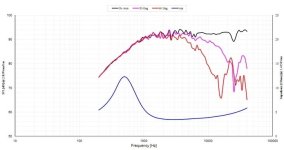
The key thing missing is baffle step compensation. Most manufacturers measure their drivers on an IEC baffle or apply an infinite baffle response. This effectively "boosts" the bass / lower midrange frequencies, making the driver appear more sensitive than it is.
This means our system sensitivity / SPL will be about 4dB lower as a target then the woofers rated / nominal sensitivity.
As an example. The pink is the spec sheet. the white is the likely curve AFTER applying baffle effects:

Also - are you checking the minimum phase checkbox on both drivers in the driver tab? What Z offset are you using for your woofer as this will affect the relative phase making your crossover summation inaccurate if not set
This means our system sensitivity / SPL will be about 4dB lower as a target then the woofers rated / nominal sensitivity.
As an example. The pink is the spec sheet. the white is the likely curve AFTER applying baffle effects:
Also - are you checking the minimum phase checkbox on both drivers in the driver tab? What Z offset are you using for your woofer as this will affect the relative phase making your crossover summation inaccurate if not set
I can tell your speaker will likely be bass weak. Unless your driver has baffle step baked in (not common) your transfer function indicates there is no baffle step compensation being applied:

In a normal 2 way sized baffle - you want up to 6dB "fall" from about 100Hz to about 1KHz, eg:

In a normal 2 way sized baffle - you want up to 6dB "fall" from about 100Hz to about 1KHz, eg:
Thank you guys for the comments. Let me share the 2 drivers SPL here as mtidge suggested. I bought these 2 from AliExpress they are called HiVi6.4+ and XT25BG60.
It’s too late to change the drivers. That’s one lesson learned for me. Luckily I haven’t bought the crossover components yet. So, I will take comments here and comeback with my 2nd revision.


It’s too late to change the drivers. That’s one lesson learned for me. Luckily I haven’t bought the crossover components yet. So, I will take comments here and comeback with my 2nd revision.
Attachments
I have some questions if you are kind to answer. So, I should use baffle effect applied SPL instead of spec sheet SPL in the cross over design right? I found Jeff Bagby excel sheet. So, I am thinking about merging baffle diffraction with driver SPL and use it aa input to crossover design. Is it the way to go?The key thing missing is baffle step compensation. Most manufacturers measure their drivers on an IEC baffle or apply an infinite baffle response. This effectively "boosts" the bass / lower midrange frequencies, making the driver appear more sensitive than it is.
This means our system sensitivity / SPL will be about 4dB lower as a target then the woofers rated / nominal sensitivity.
As an example. The pink is the spec sheet. the white is the likely curve AFTER applying baffle effects:
View attachment 1327308
Also - are you checking the minimum phase checkbox on both drivers in the driver tab? What Z offset are you using for your woofer as this will affect the relative phase making your crossover summation inaccurate if not set
For Z offset, I really don’t know what number I should use. Looking up the internet, I found only those that need measuring equipment which I do not have. Do you have any suggestion?
You have to correct the data sheet response at two points. VCad can simulate the baffle step function quite reliably. But you'll have to RTFM and apply the correction yourself. Plus: low end response of your driver-enclosure combo can be predicted too, by simming it. You also have to correct the raw response for that in VCad.
Why is baffle step a topic before the baffle itself is a topic? Is this supposed to be an infinite baffle construction? Is it supposed to be a box speaker?
Design your enclosure first (get or measure T/S parameters of the woofer, sim enclosure that meets your requirements) then measure the woofer impedance and FR in that enclosure and then you can design a crossover. And if needed put in baffle step compensation.
Design your enclosure first (get or measure T/S parameters of the woofer, sim enclosure that meets your requirements) then measure the woofer impedance and FR in that enclosure and then you can design a crossover. And if needed put in baffle step compensation.
I am not ready for measuring equipment yet.
…then measure the woofer impedance and FR in that enclosure
We do have a thread on designing a system without measurements though: https://www.diyaudio.com/community...igning-crossovers-without-measurement.189847/
I did a simulation with traced data of your chosen drivers. I used the VituixCAD diffraction tool to simulate a baffle 200mm x 330mm, I placed the mid woofer centered at 105mm and the tweeter at 240mm and the microphone centered on the tweeter axis. AliExpress does not list the Le of the HiVi midwoofer so I just adjusted the Zobel until the the impedance looked flat. I can't flatten out the 3db peak at 1khz, but who knows what will happen with actual measured data. I also had to use a 3rd order filter on the LF and 4th order on the HF. This did yield an nice deep null with the tweeter inverted.


So, my mistake is obviously the baffle effect. Thanks everyone for helping me catching this.
@mtidge Thank you very much for your help. I really appreciate this. I will take this and maybe do some adjustment based on my baffle.I did a simulation with traced data of your chosen drivers. I used the VituixCAD diffraction tool to simulate a baffle 200mm x 330mm, I placed the mid woofer centered at 105mm and the tweeter at 240mm and the microphone centered on the tweeter axis. AliExpress does not list the Le of the HiVi midwoofer so I just adjusted the Zobel until the the impedance looked flat. I can't flatten out the 3db peak at 1khz, but who knows what will happen with actual measured data. I also had to use a 3rd order filter on the LF and 4th order on the HF. This did yield an nice deep null with the tweeter inverted.
In case any body is interested I added the Zobel like circuit to the tweeter to flatten the tweeters rising response. It is acting more like a 1st order low pass.
Your woofer Z should be positive.positive Z is away from the micI did a simulation with traced data of your chosen drivers. I used the VituixCAD diffraction tool to simulate a baffle 200mm x 330mm, I placed the mid woofer centered at 105mm and the tweeter at 240mm and the microphone centered on the tweeter axis. AliExpress does not list the Le of the HiVi midwoofer so I just adjusted the Zobel until the the impedance looked flat. I can't flatten out the 3db peak at 1khz, but who knows what will happen with actual measured data. I also had to use a 3rd order filter on the LF and 4th order on the HF. This did yield an nice deep null with the tweeter inverted.
View attachment 1327513
View attachment 1327515
View attachment 1327516
Hi there. I am back with the update on my first project. I name it Rabbit Hole, since getting into this speaker building feel like going into rabbit hole to me.
I learned from this thread that I missed baffle step compensation in my crossover. So, I designed my enclosure and calculated baffle effect. Then, I revised my crossover design, and ordered my enclosure from a local speaker building shop.
Here is my drawing.

While waiting for the enclosure to be done, I did more reading on crossover design. In short, I was convinced that I should design crossover network from measurement of the actual drivers in actual enclosure. I did not plan for this at the beginning, because this might be the only speaker project for me. Anyway, I guess this pair of speakers will be with me for more than a couple years, and I was having fun doing this. So, I decided to invest in measuring equipment. Nothing fancy though, I bought some budget equipment for measuring with REW.
And this is what I got for my enclosure. The shop also made me the grilles even I did not ask for.

So, next step is to do the measurement. This is the result. Green line is the woofer, and blue is tweeter.

And this is my crossover design. It did not look perfect but I decided to go with it.

I cannot find a shop for inductors in my area. So, I made them myself.

Then, it’s time to measure the speaker with the crossover. Here’s the result.

I am happy with the result at this point, and the speakers sound nice. Thank you everyone who replied to this thread. I did learn from it. Really nice community here. And I hope this post will be beneficial to some of the newbies like me out there. Cheers.
I learned from this thread that I missed baffle step compensation in my crossover. So, I designed my enclosure and calculated baffle effect. Then, I revised my crossover design, and ordered my enclosure from a local speaker building shop.
Here is my drawing.
While waiting for the enclosure to be done, I did more reading on crossover design. In short, I was convinced that I should design crossover network from measurement of the actual drivers in actual enclosure. I did not plan for this at the beginning, because this might be the only speaker project for me. Anyway, I guess this pair of speakers will be with me for more than a couple years, and I was having fun doing this. So, I decided to invest in measuring equipment. Nothing fancy though, I bought some budget equipment for measuring with REW.
And this is what I got for my enclosure. The shop also made me the grilles even I did not ask for.
So, next step is to do the measurement. This is the result. Green line is the woofer, and blue is tweeter.
And this is my crossover design. It did not look perfect but I decided to go with it.
I cannot find a shop for inductors in my area. So, I made them myself.
Then, it’s time to measure the speaker with the crossover. Here’s the result.
I am happy with the result at this point, and the speakers sound nice. Thank you everyone who replied to this thread. I did learn from it. Really nice community here. And I hope this post will be beneficial to some of the newbies like me out there. Cheers.
- Home
- Loudspeakers
- Multi-Way
- Do I miss something in my crossover here?