I own a set of Vandersteen 2Ce Signatures. I just purchased a Vandersteen Model 2W subwoofer on eBay. It has not yet arrived, but I’ve been doing some reading, and it appears that I will need a pair of in-line crossover between the preamp and the sub. Apparently Vandersteen supplied these with the product, but they are now scarce and expensive.
Apparently, the Vandersteen x-overs were variable according to the input impedance of the amplifier. This is confusing to me. Since the sub is self-powered, I would assume that any relationship between the sub's amplifier and the preamp should be handled without an external device. If the amplifier in question is the amp that is powering the main speakers, then I’m also confused – but I’m often wrong. (FWIW, the input impedance of my main amp (PSA BHK 250) is 50K single ended and 100K balanced.)
I happened to notice a set of line of in-line crossovers from Harrison Labs (https://www.hlabs.com/products/crossovers/). The only variable with them seems to be the crossover frequency - not the input impedance of any amp.
I wonder if these crossovers would meet my requirements. Any assistance would be greatly appreciated.

If the original crossover was passive at line level, then the input impedance of the amp can affect things. More so if it's extreme.
The FMods are cheap and easy enough that they are worth a try. I think they are 12 dB/octave, while the one from Vandersteen looks like it was 6 dB/octave. Though their page/manual also talks about using an AV processor, which would also have a steeper slope.
https://www.hlabs.com/products/crossovers/index_files/Page446.htm
"The color ring indicates Hlabs standard crossover frequency (-3db point)
There is an 8%(LP) / 25%(HP) frequency increase at 10K ohms and 8%(LP) / 15%(HP) frequency decrease at 47K ohm load. Otherwise all color design values of crossover frequencies are standardized at 22k ohms. Keep in mind that exact crossover frequencies are seldom noticed or necessary.
20hz black bands (25hz @ 10K / 17hz @ 47K)
30hz 2 black bands (37hz @ 10K / 26hz @ 47K)
50hz brown band (54hz @ 10K / 46hz @ 47K) (62hz @ 10K / 43hz @ 47K)
70hz purple band (76hz @ 10K / 65hz @ 47K) (87hz @ 10K / 60hz @ 47K)
100hz has no band (108hz @ 10K / 92hz @ 47K) (125hz @ 10K / 85hz @ 47K)
150hz 2 blue bands (162hz @ 10K / 138hz @ 47K) (187hz @ 10K / 128hz @ 47K)
200hz blue band (216hz @ 10K / 184hz @ 47K) (250hz @ 10K / 170hz @ 47K)
300hz 2 white bands (375hz @ 10K / 255hz @ 47K)
500hz white band (540hz @ 10K / 460hz @ 47K) (625hz @ 10K / 425hz @ 47K)
1000hz light blue band (1080hz @ 10K / 920hz @ 47K) (1250hz @ 10K / 850hz @ 47K)
2500hz light green band (2700hz @ 10K / 2300hz @ 47K) (3125hz @ 10K / 2125hz @ 47K)
3500hz gray band (3780hz @ 10K / 3220hz @ 47K) (4375hz @ 10K / 2975hz @ 47K)
6500hz orange band (7020hz @ 10K / 5980hz @ 47K) (8125hz @ 10K / 5525hz @ 47K)"
Last edited:
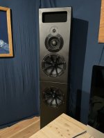
Hello everyone I recently finished a studio monitor project and i am struggling to find the crossover points of the PMC mb2s Xbd monitors witch my monitors are deigned around. I am using DSP Hypex amps to model the filters . But would be great if i could find out the original frequency's of the PMC speakers .
thanks..
thanks..
Attachments
Hi speakerBob, PMC was one of the first places I checked. My original information on the build was from DiyAudio and everyone has been most helpful over the years, and this last bit of information would finally get me over the finish line. I did at one point directly email PMC but naturally they were not very forthcoming . All the very best Bob
Thanks BoB but I was looking for some sort of visual frequency graph to copy that into my filters. excuse my ignorance , I am grate with hands construction but totally useless when it come to this side of the work.. With the 4 way crossover system i have just started with the speakers manufacturers infomation .. Thats as far as ive got.. Thanks again.
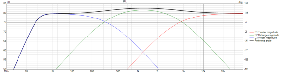
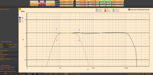
Is this the sort of graph you are looking for? This one is comprised of Linkwitz-Riley filters: a 2nd-order LP filter on the woofer section, a 2nd-order HP filter and 2nd-order LP filter on the midrange, and a 2nd-order HP filter on the tweeter. Note that the polarity of the midrange driver is reversed in order to get the correct summation to a flat response. The crossover frequencies are chosen to be 380Hz and 3800Hz, and the summation (black line) is quite flat. Of course, the natural frequency responses of each of your drivers will come into play, but hopefully this will help to get you started.

The Harrison site says ACCURACY ± 1% @ 22KΩ LOAD. That's because the crossover frequency of the passive FMods will change due to the load splitting between the monitor amp and the sub amp.I own a set of Vandersteen 2Ce Signatures. I just purchased a Vandersteen Model 2W subwoofer on eBay. It has not yet arrived, but I’ve been doing some reading, and it appears that I will need a pair of in-line crossover between the preamp and the sub. Apparently Vandersteen supplied these with the product, but they are now scarce and expensive.
Apparently, the Vandersteen x-overs were variable according to the input impedance of the amplifier. This is confusing to me. Since the sub is self-powered, I would assume that any relationship between the sub's amplifier and the preamp should be handled without an external device. If the amplifier in question is the amp that is powering the main speakers, then I’m also confused – but I’m often wrong. (FWIW, the input impedance of my main amp (PSA BHK 250) is 50K single ended and 100K balanced.)
I happened to notice a set of line of in-line crossovers from Harrison Labs (https://www.hlabs.com/products/crossovers/). The only variable with them seems to be the crossover frequency - not the input impedance of any amp.
I wonder if these crossovers would meet my requirements. Any assistance would be greatly appreciated.
I would highly recommend using a miniDSP 2x4 between the preamp and sub amp rather than the FMods, with the mains running full range. A DSP solution will allow you to select whatever crossover frequency and slope you want, and allow room and speaker corrections easily using the freeware Room EQ Wizard. I have used FMods, as well as Marchand active and passive crossovers and nothing came close to what I was able to achieve with the very inexpensive miniDSP/REW solution.
You have bought an excellent set of drivers, I have heard PMC's they were extremely good. (powered by Bryston amps)Thanks BoB but I was looking for some sort of visual frequency graph to copy that into my filters. excuse my ignorance , I am grate with hands construction but totally useless when it come to this side of the work.. With the 4 way crossover system i have just started with the speakers manufacturers infomation .. Thats as far as ive got.. Thanks again.
You owe it to yourself to buy a measuring mic and work with actual graphs from the speakers you have put all that hard work into.
Bob.
Hay once again thank you all and "Bob" so much, its reassuring that there are people here to help , Ive stated the crossover filter work and the results are very promising at the moment. The drivers are absolutely spot on , the only thing letting them down is me . But sounding good at the moment, im sure ill be tweaking for the next few weeks.🤓. I have sound id sonarworks Bod so ill be using that once i streamline my room more . I will send link so you can check out the audio once ive finished ..
Attachments
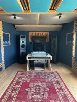
Hi, so I have a bit of a frankenstein set up , for the 3 way i am using 2 Hypex 503 and for the subs lab gruppen ipd 1200 witch has the DSP , i am using one of the Genelec sub settings and tweaking that between 80 and 30hz although Volt say 27hz .. Ayway once things are up and running ill pop back and send you all a link so you can give me some feeed back.. Many ThanksThe Harrison site says ACCURACY ± 1% @ 22KΩ LOAD. That's because the crossover frequency of the passive FMods will change due to the load splitting between the monitor amp and the sub amp.
I would highly recommend using a miniDSP 2x4 between the preamp and sub amp rather than the FMods, with the mains running full range. A DSP solution will allow you to select whatever crossover frequency and slope you want, and allow room and speaker corrections easily using the freeware Room EQ Wizard. I have used FMods, as well as Marchand active and passive crossovers and nothing came close to what I was able to achieve with the very inexpensive miniDSP/REW solution.
Hi, so i have been at this filter design for , weeks , the graph above is pretty much where i am at the moment. My main issues are , I cant independently drop the gain on channels without affecting one or two of the other crossover points and phase being pulled out. At this point to be perfectly honest I would not had bothered getting theses plate amps in the first place because of the hassle .. Any of you guys have a photo of what a good 3 way filter design should look like ? The 10 filters on each channel interact across the board so no matter what i do everything has a knock on affect . The 503s that I have ive been told you cant import filter templates as that at least would be a step in the right direction for me , also getting a seasoned professional to help me would be marvelous. Many Thanks as always..Is this the sort of graph you are looking for? This one is comprised of Linkwitz-Riley filters: a 2nd-order LP filter on the woofer section, a 2nd-order HP filter and 2nd-order LP filter on the midrange, and a 2nd-order HP filter on t muhe tweeter. Note that the polarity of the midrange driver is reversed in order to get the correct summation to a flat response. The crossover frequencies are chosen to be 380Hz and 3800Hz, and the summation (black line) is quite flat. Of course, the natural frequency responses of each of your drivers will come into play, but hopefully this will help to get you started.
View attachment 1317745
Hello. If you will, please show us some plots and/or screen snapshots of the settings that you have arrived at and are using with your Hypex 503 amplifiers. At the moment it's difficult to provide any sort of reasonable suggestions as the problem is quantitatively unknown.
Below is a model of a theoretical 3-way loudspeaker system comprised of filtered acoustic 2nd-order Linwkitz–Riley filter transfer functions. By adjusting the midrange's output level, it's possible to get a very flat response.

In the model, I can adjust the gain on the midrange channel by +3dB, and I get the following result:

It's apparent that the boost in overall midrange level at 1kHz is about 2.7dB. This is because the filtered response of the midrange doesn't quite have the true Linkwitz–Riley manitude and phase response characteristics. Having said that, it's still quite close.
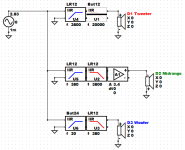
The VituixCAD circuit that I've used to model the above is:

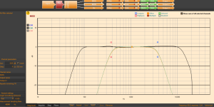
If we increase the filter order to use 4th-order Linkwitz–Riley filter functions, the following result is obtained:

In the above case, the circuit that was used is shown below:

In this instance, if the gain on the midrange channel is increased by 3dB, the following result is obtained. It is apparent that the region of interaction is much reduced by the use of the 4th-order Linkwitz–Riley filters, and the lift is essentially equal to the dialed-in 3dB of boost.

Below is a model of a theoretical 3-way loudspeaker system comprised of filtered acoustic 2nd-order Linwkitz–Riley filter transfer functions. By adjusting the midrange's output level, it's possible to get a very flat response.
In the model, I can adjust the gain on the midrange channel by +3dB, and I get the following result:
It's apparent that the boost in overall midrange level at 1kHz is about 2.7dB. This is because the filtered response of the midrange doesn't quite have the true Linkwitz–Riley manitude and phase response characteristics. Having said that, it's still quite close.
The VituixCAD circuit that I've used to model the above is:
If we increase the filter order to use 4th-order Linkwitz–Riley filter functions, the following result is obtained:
In the above case, the circuit that was used is shown below:
In this instance, if the gain on the midrange channel is increased by 3dB, the following result is obtained. It is apparent that the region of interaction is much reduced by the use of the 4th-order Linkwitz–Riley filters, and the lift is essentially equal to the dialed-in 3dB of boost.
Attachments


Your simulated results seem to be very flat. Tweaking the settings might not result in a noticeably better response.
As the amplitude at crossover is -3dB, it looks like you might be using 4th-order Butterworth filters for the high-pass and low-pass sections. Is that correct? If so, I'm a little surprised that you are getting such a smooth summed response.
As the amplitude at crossover is -3dB, it looks like you might be using 4th-order Butterworth filters for the high-pass and low-pass sections. Is that correct? If so, I'm a little surprised that you are getting such a smooth summed response.
Yes they are butterworth , as I said befor I not at all familiar with any of this sort of thing, Im realy a building hands on guy.. everything is just trial and error at the moment. that response is because i used a filter on the mid to get it
So when I meen tweeking, I meen designing the filters, one of the problems is mid is way to loud and the bass needs a boost . Using all the filters to get the outcome i would like is not easy..Your simulated results seem to be very flat. Tweaking the settings might not result in a noticeably better response.
As the amplitude at crossover is -3dB, it looks like you might be using 4th-order Butterworth filters for the high-pass and low-pass sections. Is that correct? If so, I'm a little surprised that you are getting such a smooth summed response.
Does the Hypex filter designer provide options for filters that are called "Linkwitz–Riley"? If so, I'd suggest giving them a try, as they would have much lower interaction effects between the filtered responses of the drivers. That way giving the midrange a few dB of cut, plus boosting the bass by a dB or two, should still enable a fairly reasonable summed response. It seems that the drivers you have chosen may have different sensitivities, which needs to be accounted for in the amplifier settings. When using 4th-order Butterworth filters, the total (summed) response is quite sensitive to the phase response between the drivers.
Of course, the natural response of the chosen drivers isn't contributing to these simulations, so you could be out by quite a few dB. Do you have any measured responses of the individual drivers, say at a 2 metre listening distance on the axis of the tweeter, with and without each driver's filter/s in place?
Of course, the natural response of the chosen drivers isn't contributing to these simulations, so you could be out by quite a few dB. Do you have any measured responses of the individual drivers, say at a 2 metre listening distance on the axis of the tweeter, with and without each driver's filter/s in place?
I’ve take a look at the manual for the Hypex Filter Design program. It does support Linkwitz–Riley filters.As you’ve used 4th-order Butterworth filters, may you needed to try different Q values in the bi-quads to get a reasonably flat summed response? It’s only a guess on my part.
For 4th-order L–R filters the manual describes how to create them from cascaded 2nd-order biliary filters with certain frequency and Q settings. I’d suggest implementing these 4th-order L–R filters as the low-pass and high-pass sections for your drivers. That should give you the best boost/cut capability for each section while still maintaining a good summer response.
Adding some delay to the tweeter section, and possibly even to the midrange, may get the phase response to be more in-phase through the crossover region. That will provide the best blending of the response for the L–R topology, as that is its key design feature. In-phase crossover designs help to prevent off-axis lobing from occurring in the crossover region.
Once you get some real driver measurements added, their natural responses can be EQed a bit to get the filtered response looking like the theoretical response. The theoretical response is the filtered target response that we are trying to get each driver to follow once the filters are in place and activated.
- Home
- Loudspeakers
- Subwoofers
- Crossover questions