Okay, that's promising then. For Linkwitz–Riley filters, the Q values of each of the two biquad filters are identical, be they a pair of low-pass filters or a pair of high-pass filters. For the two biquad filters, each needs to be set to Lowpass2 (2nd-order) and the Q should be set to Q = 0.71. This will work to produce the desired 4th-order L–R filter response function. Of course, for the midrange you will need a total of 4 biquads, two for the high-pass filter and 2 for the low-pass filter.

Of course, a Linkwitz-Riley filter is no longer a Linkwitz-Riley filter once it combines with a real driver response. It doesn’t retain the original properties.That’s what I’ve been using,
@Amami Life Thanks to your tip, I've got the Hypex Filter Design program working on my PC.
I've gone and set up the following filter functions:
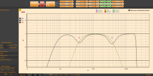
The summed response that is produced with in-phase (non-inverted) settings on each channel is shown below. Although similar to your simulations, I note that you have the "Invert" option checked, whereas my simulation doesn't. Note that a 4th-order LR filter doesn't invert any of the channels. My results essentially agree with a VituixCAD model of the same configuration.

My midrange filter design has "Biquads remaining: 11", while yours has "Biquads remaining: 9". As a result, you may have extra biquads active, which are affecting the response function in some way, leading to "Invert" being active to get a flat response.
If I switch on "Invert" for the Midrange section, I get the following response. Here it is apparent that some nulls are starting to appear at the crossover frequencies. This is to be expected. The fact that they are not deep nulls is indicative of some phase errors in the crossover regions, whereby the responses are not truly of Linwkitz–Riley characteristics.

If I perform the same "Invert" operation on the Midrange driver in my VituixCAD model, I get the following response. This is closer to the ideal at the crossover point between the midrange and the tweeter, which is to be expected as the tweeter is "perfect" and doesn't have any phase response of its own. The depth of the notch in the VituixCAD model at 380Hz matches very well with that produced by the Hypex Filter Design program.

I've gone and set up the following filter functions:
Driver | LR4 Highpass Filter Cutoff Frequency | LR4 Lowpass Filter Cutoff Frequency |
Woofer | 80 Hz | 380 Hz |
Midrange | 380 Hz | 3800 Hz |
Tweeter | 3800 Hz | – |
The summed response that is produced with in-phase (non-inverted) settings on each channel is shown below. Although similar to your simulations, I note that you have the "Invert" option checked, whereas my simulation doesn't. Note that a 4th-order LR filter doesn't invert any of the channels. My results essentially agree with a VituixCAD model of the same configuration.
My midrange filter design has "Biquads remaining: 11", while yours has "Biquads remaining: 9". As a result, you may have extra biquads active, which are affecting the response function in some way, leading to "Invert" being active to get a flat response.
If I switch on "Invert" for the Midrange section, I get the following response. Here it is apparent that some nulls are starting to appear at the crossover frequencies. This is to be expected. The fact that they are not deep nulls is indicative of some phase errors in the crossover regions, whereby the responses are not truly of Linwkitz–Riley characteristics.
If I perform the same "Invert" operation on the Midrange driver in my VituixCAD model, I get the following response. This is closer to the ideal at the crossover point between the midrange and the tweeter, which is to be expected as the tweeter is "perfect" and doesn't have any phase response of its own. The depth of the notch in the VituixCAD model at 380Hz matches very well with that produced by the Hypex Filter Design program.
Last edited:
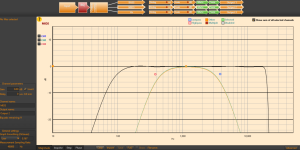
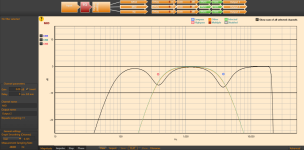
The above results for the 3-way LR4 crossover network display a small dip at about 4.5kHz. It is possible to reduce the severity of this dip by setting Gain = +0.2dB and Delay = 32 us for the Midrange. The results are shown below. Note that I have been using "Graph Smoothing (Octaves)" set to 0.001 (None). The curves are quite smooth in and of themselves, so no smoothing is required.

It is possible to reduce the severity of the minor dip at 350Hz by setting Gain = +0.7dB and Delay = 160 us for the Woofer. The resulting summed response looks like the following. Note how flat the response is.

Now if we invert the polarity of the midrange, we get the following. The second null is now very sharp and deep, while the first null is somewhat deeper than it was before.

It is possible to reduce the severity of the minor dip at 350Hz by setting Gain = +0.7dB and Delay = 160 us for the Woofer. The resulting summed response looks like the following. Note how flat the response is.
Now if we invert the polarity of the midrange, we get the following. The second null is now very sharp and deep, while the first null is somewhat deeper than it was before.
Last edited:
Ok here we go again , so your own outcome is almost exactly the same as mine, however, once again the MID is way way way to loud , and adjusting the gain will pull the crossover points out. Even with my adjustments you can see , the gain still needs to come down and bass up , not as much as last time but still needs to be done,, this is the part that Hypex say its to be exspected ... so i m sort of back to square one again..
Attachments

yes i can definitely get your outcome with the Linkwitz-Riley filter, but once there thats when the isses start ...
Up to this point i have tried everything , even taking everything back to factory default. When i speak to hypex they give me a link to you guys,, basically brushing me off ...
Up to this point i have tried everything , even taking everything back to factory default. When i speak to hypex they give me a link to you guys,, basically brushing me off ...
Attachments

Last edited:
Okay, I've taken a look at your plots, and will offer a few comments.Ok here we go again , so your own outcome is almost exactly the same as mine, however, once again the MID is way way way to loud , and adjusting the gain will pull the crossover points out. Even with my adjustments you can see , the gain still needs to come down and bass up , not as much as last time but still needs to be done,, this is the part that Hypex say its to be exspected ... so i m sort of back to square one again..
I am very surprised that you have added a delay of 19,200 us. This corresponds to placing the midrange 6.6 meters behind the woofer! Something has definitely gone awry. The delay on the tweeter is also very large, at 2005 us, which corresponds to placing the tweeter 0.69 meters behind the woofer. Something is very wrong here.
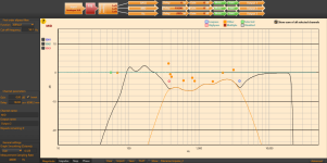
Looking at "Screenshot bass", I see you have an allpass filter in the chain. Why is that? I would say it is quite unnecessary. There are also a lot of orange dots peppered around the bass response. What sort of DSP filtering have you added and why? It seems excessive to have that many present.
Looking at "Screenshot hz", you have an allpass filter (green dot) and some other filters (orange dots) present. What are they and why did you include them?
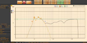
Looking at "Screenshot mid", you have a large number of extra filters (orange dots) present. Why did you include them and what are they doing?
All I can guess is that you are trying to perform some sort of equalization of the driver frequency response functions. If so, how are you introducing the driver responses into the Hypex Filter Design program. I believe that they need to come in as a set of impulse response measurements. Have you taken those types of measurements of your drivers individually driven when mounted on the baffle of the loudspeaker?
I'm sorry for the large number of questions, but I am trying to get my bearings as to what you have implemented so far.
Hypex has provided some data ' impulse response' and so on as a starting point ive been using them. the only measurements i have done is with sonaworks , also i tried REW BUT could not get that to work with my UAD audio interface.. i am just winging it at the moment as i am fed up with the hole thing,, present company excepted...All I can guess is that you are trying to perform some sort of equalization of the driver frequency response functions. If so, how are you introducing the driver responses into the Hypex Filter Design program. I believe that they need to come in as a set of impulse response measurements. Have you taken those types of measurements of your drivers individually driven when mounted on the baffle of the loudspeaker?
Sonarworks should be able to take measurements of the raw response of each of your drivers: woofer, midrange, and tweeter. You will need to ensure that the microphone is stationary for all measurements on the tweeter axis (or the midrange axis). The amplifier output to each driver must be identical. No DSP filtering should be used.
Now, can Sonarworks provide an impulse response for each of the drivers? That's usually calculated from a frequency sweep of some kind, or using an MLS excitation signal. If you can get those sorts of test measurements, maybe you can share them via Dropbox or similar?
I need to read up on what Sonarworks can do as far as measurements goes...tomorrow, though.
importing files to the amps i have dosnt always work as i got the 503 plate amps some years ago and Hypex have not updated the firmwear , thats way i have only used what they provided. again you can find the data on hypex site free download.. thats what i have been using ..i also tried the EQ but this also efects the crossover curve .. you need the hardwear to use that..
Last edited:
Depending on where it is applied, EQ can definitely affect the crossover curve. Which revisions of the two sets of firmware are you using in the 503 plate amps?
When you refer to "data on Hypex site free download", do you mean the tweet.dat, woof.dat, and flat.dat files that come with the Hypex Filter Design program zip file? That's all that I could find, and I believe that these are just impulse responses for some unknown drivers.
When you refer to "data on Hypex site free download", do you mean the tweet.dat, woof.dat, and flat.dat files that come with the Hypex Filter Design program zip file? That's all that I could find, and I believe that these are just impulse responses for some unknown drivers.
So I have 2 fa503 that dont support FIR files. And yes tweet.dat, woof.dat, and flat.dat files that come with the Hypex Filter Design. I originally started off by using a basic design, and this is when i ran into the gain problem, and custom tweeking the filter. Getting the crossover outcome to fit at the 380/ 38000 isnt a problem ,, ive done it so many times now i can do that blindfolded ... its a bit of a chalange to do the rest ..Depending on where it is applied, EQ can definitely affect the crossover curve. Which revisions of the two sets of firmware are you using in the 503 plate amps?
When you refer to "data on Hypex site free download", do you mean the tweet.dat, woof.dat, and flat.dat files that come with the Hypex Filter Design program zip file? That's all that I could find, and I believe that these are just impulse responses for some unknown drivers.
That's an interesting video. I was a bit surprised at the use of the coaxial driver in a design. The midrange and tweeter need a lot of equalization to achieve a flat response. I'm not entirely sure that's a good design method, but it does produce a flat response, albeit after heavy EQing.
In your design, which tweeter model are you using? I am trying to create impulse responses to load into Hypex Filter Designer. After tracing the frequency a response curve in VituixCAD, I can get the minimum-phase response. This can then be inverse-FFTed to produce an Impulse Response.
I keep getting access violation errors when loading an impulse response. I can't determine what's wrong with my text file that's filled with impulse-response data lines, as I believe I followed Hypex's guidelines.
I've created minimum-phase frequency response models of the Volt woofer and midrange, and converted them to impulse response functions. These have been loaded into HFD. The following summation has been obtained, with the midrange amplification dropped by about 4dB due to its greater sensitivity. So far the results look reasonable to me. Once I have a model of the tweeter's response, then we can proceed further. These models don't include any baffle diffraction step at this stage.
Can you provide a drawing of the front baffle with dimensions showing the locations of the drivers?


Can you provide a drawing of the front baffle with dimensions showing the locations of the drivers?
In your design, which tweeter model are you using? I am trying to create impulse responses to load into Hypex Filter Designer. After tracing the frequency a response curve in VituixCAD, I can get the minimum-phase response. This can then be inverse-FFTed to produce an Impulse Response.
I keep getting access violation errors when loading an impulse response. I can't determine what's wrong with my text file that's filled with impulse-response data lines, as I believe I followed Hypex's guidelines.
Hypex seems to be a very twitchy bit of software. I to get the same violation errors, i dont take any notice of them. So after your last visit , i replicated your filter crossover. redused the gain on mids and Hz , and also very carefully manipulated the phase , Yes its sounding much better since your last visit, and taking your advice. Its a fine combination of keeping the crossover in chack and EQ ing the over all sound . I have used many studio monitor, My last ones were Genelec 1033a i used for mastering, great speakers but not up to the job today. So this is why i do alot with my trusted ears,,
- Home
- Loudspeakers
- Subwoofers
- Crossover questions