comments on thermal distortion?

I'm interested in hearing what others have to say about this site: http://peufeu.free.fr/audio/, and the thermal "memory" distortion ideas Pierre has presented there.

Personally, I think he's done an excellent job with the simulations, although I don't know if I like the solutions he presents as much. In particular, the cascoded CFP diff pair seems rather complex. At some point I might try it, perhaps with the cascode FET repositioned so the gate is connected to the main transistor's emitter instead of the base, and so that the FET lies between the two BJTs that make up the CFP... stability could be a serious issue here though.

When you consider the tiny thermal mass of a transistor's guts, and the time it will take any transient heat buildup to dissipate out through the case, I don't find it the least bit surprising that transistor parameters vary by large amounts. I'm sure the dynamic effects are rather more complex than Peirre's simulations indicate. Perhaps this is a good reason to use transistor pairs like the MAT02, where the thermal coupling is tight, and the pair remains closely matched...

Comments? Flames? Has anyone tried these circuit modifications?

Pro-ject arm on Rega Planar 2

I have an old (NAD branded) Rega Planar 2 turntable with no arm (I transferred it to a Michell turntable) and I was wondering if anyone has had any success mounting a Pro-ject arm such as one of those here https://www.analogueseduction.net/tonearms/pro-ject-replacement-tonearms-spare-parts.html on a Rega plinth? (They are so much cheaper than Rega arms, and the plinth would require surgery anyway due to the Rega mount having changed, and even a second hand RB250 looks expensive, even for fairly beaten up examples.)

I understand the crucial thing is arm effective length and that Pro-ject arms have a longer effective length than Rega arms, so one question I have for anyone who has attempted this is about whether the overhang at the counterweight end might move beyond the boundary of the plinth while playing, making it impossible to close the lid?

Also, in general, how easy is it to find the proper measurements for mounting, and any other things I should look out for?

Thanks.

Primitive Root Diffuser Calculator

I came across this so I figured I'd share it.

It calculated and generates a diffuser for breaking up frequency ranges.

Would be interesting to 3d print some and place them in enclosures behind the drivers. I believe some Comercial companies have started doing this.

https://actools.tunetown.de/prd/?fb...X1z2MfHmDLEOkQ5W_k_aem_zAn63pBPAArx9HTb5seVKw


Screenshot_20240714-111556.png

OB speakers on Facebay

I found these for sale on Facebook market place.
I have the sellers permission to share the pictures.
I'm doing so because I happen to have all of the drivers except the Visaton tweeter and that XO is one I got on eBay last month. I like the way the woodwork is done and the wiring is neat but I'd not use the spacing this builder has. I also suspect that the dome midrange is possibly not Dynaudio but the cheaper Jaycar/Dayton clone. The baffles do look good and I know how much they would cost from Bunnings hardware. Unsure tho of the the long term stability. Seller wants $1500- I got my drivers on sale and paid $20- for the woofers. Woofers have a Q of 1.7 and actually sound pretty good but can only handle about 30 W max
I've had the drivers for ages but haven't got around to making anything with them because big OB speakers need a bigger room than I have here

Attachments

  • 442099564_1428559114508971_1311841612971685097_n.jpg
    442099564_1428559114508971_1311841612971685097_n.jpg
    117.2 KB · Views: 109
  • 442488911_1154303489095824_20050222374628835_n.jpg
    442488911_1154303489095824_20050222374628835_n.jpg
    123.7 KB · Views: 108
  • 443006427_367734206334196_8702305155196961756_n.jpg
    443006427_367734206334196_8702305155196961756_n.jpg
    116.4 KB · Views: 110

Cheap and FAST OB, Literally

Edit April 28, 2022 - XSD Speaker is here: 8x 6.5in woofers, 5.25in neodymium motor paper midrange, 3in planar dipole tweeter. 91.5dB sensitive st 2.83v, -3dB at 43Hz and -6dB at 37Hz.

1651190331950.jpeg


1651190465718.jpeg


Cheap and fast FAST bi-amped OB

Edit: latest results with 6 driver slot loaded woofer - see post 67.

397658d1391479751-cheap-fast-ob-literally-slot-ob-photo-01.jpg


397656d1391479751-cheap-fast-ob-literally-slot-ob-meas-thd.png


Having a bunch of Vifa TC9FD's in hand from when they had the sale for $10 ea, and a few more of the PE 6.5 in polycone woofers (part 299-609) for $4.88 ea lying around... I thought I should try a FAST open baffle, that can be made in less than 1 hr. Having measured both of these drivers in a 24 in x 36 in cardboard baffle before, I knew they had very flat responses, and being high Qts drivers would lend themselves to an OB. I also happen to now have a miniDSP to handle the XO and EQ duties, and I planned to bi-amp them. I am convinced that messing with huge inductors, and huge poly film caps for a passive XO will end up costing just as much as a minDSP and a pair of class D amps.

I happened to have some double-wall corrugated cardboard on hand that measured 12 in x 18 in. Guess what, that is now my OB baffle size. I had some more cardboard that I used to make some wings and the stand for the baffles. These ended up as 8 in deep at the base and going to 3 in deep 15 in up. I gave a tilt backwards to add stability and aim it up. The 6.5 in woofer is mounted 5 in from the bottom at the middle. The Vifa fullrange is mounted 5 in from the top and 4.5 in from one of the edges. I made it asymmetric to reduce diffraction. I added a 2.75 in deep cross brace on the back that will also come in handy for the binding posts. Everything was cut and tacked with a few points of hot melt and glued with Titebond at all seams. Cutting and gluing took 30 minutes. Screwing the drivers in and adding crimped connectors took another 15 minutes. Waiting for the glue to dry took 3 hours.

I tried running both drivers in parallel and full range to see what it sounded like - just a terrible mess. I then connected the drivers in a bi-amp configuration and driven by the miniDSP with a 24 dB/oct XO at 300 Hz.

The miniDSP setup took 15 minutes. Taking a measurement with the mic showed that it was pretty good but had a few minor dips and peaks that were easily EQ'd out. The bass extension is natural - no EQ'ing needed - it really does go to 50 Hz with the modest wings.

Here is the frequency response and distortion - nice flat response and low THD from the Vifa above 300 Hz. Below 300 Hz, the 6.5 in driver's cone excursion is starting to get taxed and hence THD goes up. Adding more woofers will reduce excursion and reduce THD. If I had more drivers, I would have used two in series for 8 ohms.

395984d1390704059-cheap-fast-ob-literally-cardboard-ob-03.png


Here is the impulse response - doesn't get much better than this.

395985d1390704059-cheap-fast-ob-literally-cardboard-ob-04.png


So how does it sound? Fantastic! It has some very nice clean dynamics capable of reproducing fast transients and percussion. It doesn't go very loud as the Vifa is nominally 85 dB at 2.83V but perfect for near field or low level listening. The sound stage is what is perhaps the best part - very wide and I can close my eyes and pinpoint the location of the singer, the instruments, and where they are positioned on the stage.

Anyhow, not including glue drying time, all this was done in about 90 minutes. Cost is $20 per speaker including binding posts. Now that is a cheap and fast FAST that sounds great and measures well.

Attachments

  • Cardboard-OB-00.jpg
    Cardboard-OB-00.jpg
    205.3 KB · Views: 9,672
  • Cardboard-OB-01.jpg
    Cardboard-OB-01.jpg
    170.3 KB · Views: 3,697
  • Cardboard-OB-02.jpg
    Cardboard-OB-02.jpg
    170.3 KB · Views: 3,291
  • Cardboard-OB-03.png
    Cardboard-OB-03.png
    135.3 KB · Views: 17,164
  • Cardboard-OB-04.png
    Cardboard-OB-04.png
    46.7 KB · Views: 15,492
  • Like
Reactions: Alexium and Gadgety

Hello audio doers!

Thx for having me. Joining from Portugal. Actually today I’m in Stuttgart but that’s an exception. I’m getting more interested in amplifier repairs since setting up a forgotten Denon AVR that I acquired in Shanghai 14years ago. Since then, I’ve sold it to buy a different model which I had to repair. I confess I prefer that part, repairing I mean. Since my ears and brain no longer process frequencies above 13khz I’m now setting a THD measuring lab. All budget friendly because … well Portugal.

Hello Everybody

Ok, I've been on this forum many times but it's my first time posting. I am interested in pairing a Ganfet amp with field coil speakers. Something tells me there is a big future in both of those technologies. So I will be posting a lot as I will refurbish a set of 1929 RCA field coils using my own cone, voice coil, and surround. Hopefully we can learn together as I am excited to show off my creations. Thanks

Anyone got the plans to Travelers by Campbell and Holtz? Also a few more questions

I'm about to start building either the Travelers or Anthology II speakers. I'm only missing the plans for the Travelers, and I'm leaning towards starting with them since they are smaller and seem a bit easier to construct. Before I order the plywood and drivers, I'm wondering if the Anthology IIs are even worth considering, since I'll probably add a subwoofer eventually.

My living room is 6m x 5m (20ft x 16.5ft), and I can afford to place the speakers 10-14 inches from the wall. My listening position is 10 feet away, and I don't typically listen at high volumes. Although I don't spend much time in the sweet spot, I would like to have an enjoyable experience when I do sit down for a critical listening session. What are your thoughts? Do you reckon travelers are an improvement in the mid and high range over the anthology?

Also I'm a bit confused on the travelers Hiquphon tweeter. Is it supposed to be OW2, OW2-92 or OW2x? I think it's the same thing, but I heard something about them being different at some point of time.

Thank you very much <3

Btw I sent out an email at their website a month ago asking for the plans but didn't get an answer back :/

Free transistors, exclude shipping & handling

Hi,
If anyone has any schematics or even better complete audio project how to use them, I would appreciate,

Otherwise, short list to whom is interested; here is roughly whats in my shoe box. These are all purchased 20 + years ago, part of closed down repair shop,
all of those are in qty of few, I mean more than one transistor:

C3152
D1497 (Hitachi)
BU2500

TO3:
  • BUX47
  • BU326A
  • BU414A
  • S2818
  • BU208 Toshiba
  • BU526
-
BU508aw, many of them
S2055A Siemens, also many of them

There is probably more parts, you can ask.

In any case, if anyone wants them please compensate me for packing and posting time and cost, parts are free.

Cheers,
Drazen

Hi from California

Hi All,
I just joined DIY Audio and looking forward to learn from this exciting group of enthusiasts.

One newbie question.

I have some great speakers, T+A A2D Solitaire. See attached. The electronics is not working and the speakers have not played for years. But the cabinets are fantastic and would be great for a hobby project. I simply do not have the time but I was hoping to find someone within DIY Audio that have that itch and drive to create something great.

Let me know
AudioFreakish

Attachments

Capacitance & Moving Magnet Cartridges

I thought that the following, written by Tim Fox EEVblog, might be helpful to some.
"Many MM cartridges specify a load capacitance: this value (200 to 500 pF, IIRC) with the mechanical components of the cartridge affects the resonance of the electromechanical circuit to improve the frequency response.
I first noticed this specification when Shure introduced the V15 series in the mid-1960s; the V15-III specified a load of 400-500 pF in parallel with 47kΩ, 70kΩ max.
It does vary between cartridge models.
It can also help with reducing RF interference.
The nominal 47k resistor specified for almost all MM cartridges does provide damping of the resonance, along with electrical and mechanical losses inside the cartridge itself.
"Damping" of a resonance requires resistance (electrical or mechanical): capacitance or inductance re-tunes the resonance.
Electromechanical systems are very interesting, but I will refer you to textbooks for detailed understanding.
Strictly mechanical systems, such as a car suspension, have a primary resonant frequency from the mass m and the spring constant k: w0 = (k/m)1/2.
To damp that, the shock absorber exerts a force that opposes the velocity to provide mechanical resistance.
Note that damping requires a force proportional to velocity, not a frictional force independent of velocity.
In the shock absorber, this results from a viscous liquid being pushed through small apertures: another term is "dash pot".
For the MM cartridge, the interaction between the (fixed) coil and the moving magnet gives a voltage source (proportional to the magnet velocity), and the current through the coil applies a proportional force to the moving assembly.
The voltage induces a current in the total electrical circuit, which includes the electrical inductance of the coil, its electrical resistance, and the external impedance of the amplifier.
Now, mechanically, the variables are velocity and force: force times velocity is power.
Electrically, the variables are voltage and current: voltage times current is also power.
You can convert the mechanical part of the system into an equivalent electrical circuit, replacing force and velocity with current and voltage, and the parameters mass and compliance (inverse of spring constant) with equivalent capacitance and inductance (I forget which order), add the electrical components, and you get two coupled resonant circuits that transform the needle velocity to the amplifier input."

Tannoy LSU HF 15 (Reds) / crossover HPD?

Hello,
I have a Tannoy LSU HF 15 (Reds) from around 1962. The speakers are all original, which is a good thing. The speakers do sound a bit shrill in the high tones, though.
I think the crossovers (capacitors) are no longer OK due to their age. I don't want to change the original crossovers.
Does it make sense to try out the crossovers for the 15 HPDs? I still have them here.
The Reds are specified as 15 ohms. The HPD crossover for 8 ohms. Does that even make sense??

If anyone has good homemade crossovers or used ones for the Reds, I might be interested.

Best wishes, Klaus

Final 0.4 MkIII Electrostatics

Hi to all.
I recently purchased a pair of these speakers. With the speakers came two different 12v adapters. One was a 0.5va and one was a 1.54va.
Upon listening i found that the 0.5 was not powering the panel ( I did alternate supply to each speaker to confirm it was supply problem and not speaker)
My first port of call was to contact Final where i was informed the 0.5va - 6watts according to Mr Ohms - is enough to power the speakers and that as it wasn't, the problem must be the internal transformer. Now... as the 1.54va seemed to power the panel I thought until I get time to get the speakers looked at and the internal boards tested I would buy another 1.54va supply just so as i could get a good idea of what the speakers sound like. Not able to find a 1.54va I settled for two 2va adapters so at least the supply was matched.
This itself presented another problem as for some reason I cannot seem to hear either panel now!! When i sit back and play some tunes that I'm familiar with everything sounds as it should. The soundstage is huge, the trebles are there and it does sound very good but upon standing in front of the panel I'm not hearing anything!! Am I missing something?
Note: I am using a modded Cyrus 2 + PSX

Anyone has build Tannoy Autograph like speaker with different concentric driver?

Who has build a similar Tannoy Autograph type of loudspeaker with different concentric drive unit?

I want to use this 15" concentric driver.

Attachments

  • tb_image_share_1713115089927.jpg.png
    tb_image_share_1713115089927.jpg.png
    143.8 KB · Views: 42
  • tb_image_share_1713115076303.jpg.png
    tb_image_share_1713115076303.jpg.png
    167.4 KB · Views: 41
  • tb_image_share_1713115071068.jpg.png
    tb_image_share_1713115071068.jpg.png
    179.9 KB · Views: 41
  • tb_image_share_1713115061848.jpg.png
    tb_image_share_1713115061848.jpg.png
    216.4 KB · Views: 45

Assembled and working DimDim isolator for Twisted Pear Buffalo III Pro SE

Hi All...

Up for sale is a completed working Dimdim I2C isolator with Sainsmart 4.3" screen and Arduino Due. The screen pristine, the protective layer is still on it.

This will control your Twisted Pear Buffalo III Pro SE. The code is loaded on the Arduino and will power up and run as soon as power is applied.

See pics below, asking $125 Shipped in the US. International ok, but will cost $10-$12 more for shipping


IMG_2624.jpg
IMG_2625.jpg
IMG_2626.jpg
IMG_2627.jpg

Problems with transistors (MOSFETS) for NASA

I thought this was interesting. Jovian radiation can peak at 50 times that experienced on earth. Full story is in the New York Times, July 13, 2024

NASA Mission to Europa Imperiled by Chips Aboard Spacecraft

Transistors on the Europa Clipper spacecraft, scheduled to launch in October, may not be able to endure the harsh radiation around the planet Jupiter.

By David W. Brown
David W. Brown is the author of a book about the quest to study Europa, and has written for The Times about the discovery of the moon’s ocean.
July 11, 2024
NASA said on Thursday that it is studying the durability of transistors on a $5 billion spacecraft to Europa, Jupiter’s ocean moon, which has led to concerns about the spacecraft’s ability to function as originally planned in the heavy radiation around the solar system’s largest planet.
The equipment issue on the spacecraft could result in a lengthy delay of the mission, Europa Clipper, which NASA classifies as “flagship,” a designation for its most scientifically significant endeavors. Experts say that if the spacecraft launches in October, as scheduled, it may fall short of its scientific objective of assessing whether anything could live on Europa.
At issue is the ability of the transistors, the electric switches that are the building blocks of computer chips and other electronics, to resist the powerful radiation of the Jovian system.
Space is awash in radiation caused by forces such as cosmic rays and solar eruptions, and every spacecraft requires some level of radiation protection. But Europa orbits inside a particularly perilous region of space called the Jovian radiation belt, where conditions can be over 50 times more radioactive than those found around Earth.

What's wrong with fuses (in audio signal)?

Fuses are mostly used in mains lines or in power supplies. Why are they hardly used in the audio output? Do they affect sound quality? Do they introduce distortion of the audio? How?

I am asking because I was thinking of using fuses in the output of an electrostatic headphone amplifier, which uses several hundred volts at the audio output. You don't want accidents with high voltage pushing unhealthy amounts of current through the listener.

For Sale State of the art: Transformers, chokes, OPT and IT

Hi everyone,

I am changing my life and as such, selling off my remaining DIY audio inventory. Hoping to find good homes for these products. All products come with a 5 day return policy (less shipping). Here is what I have available. Let me know if you have questions or need photos. Accepting reasonable offers. Please email for pricing - banpuku@mac.com.

As many of you know, Muse Coil Minotaur series is the creme-de-la-creme. It doesn't get any better. Please email me if you have any interest/questions/pricing.

Thanks, Pat


Muse Coil Transformers and Chokes Minotaur Series

2 x power transformer: 0-120-125Vac primary; 550-440-275-165-0-165-275-440-550 @ 50mA (10mA extra headroom). (please email for pricing - banpuku@mac.com)
2 x power transformer: 0-120-125Vac primary; 800-654-580-0-580-654-800 150mA & 130-0-0-130V secondary #2. (please email for pricing - banpuku@mac.com)
2 x L1 choke 30H 25mA 250Vac 23Rdc. (please email for pricing - banpuku@mac.com)
2 x L2 choke 16H 25mA 125Vac 27Rdc. (please email for pricing - banpuku@mac.com)
2 x L1 choke 12H 150mA 400Vac 25Rdc. (please email for pricing - banpuku@mac.com)
2 x L2 choke 7H 150mA 150Vac 23Rdc. (please email for pricing - banpuku@mac.com)
2 x Interstage Transformer 120H 30mA (new). (please email for pricing - banpuku@mac.com)
2 x Muse Coil OPTs: 9.1K - 4/9/16 ohm, OCC + OFC. (please email for pricing - banpuku@mac.com)
  • Like
Reactions: dubadub

Chinese AK4497 DAC dual-chip decoder board

Hi all,

I just got my AK4497DAC board up-and-running.

The optical input works fine for 44.1KHz and 96KHz sample rates but nothing higher. I would expect it to go higher than that with the specs saying "PCM format supports up to 384K". Any suggestions on that?

I attached an Amanero USB board but I'm getting nothing from that at all. I'm guessing that the board needs it's own 3.3V supply.

The DAC board only has provision for pins 3 through 7 which doesn't include the 3.3V and GND pins on the USB board.

Do I need an additional 3.3V supply?

If so, I'm also guessing that I need to connect the 3.3V supply earth to the DAC board earth somehow? The DAC board supplies are all AC.

Off course the DAC board didn't come with any information.

Meanwhile some 44.1KHz and 96KHz listening tests.

Thanks, Dave.

Attachments

  • AK4497 DAC.png
    AK4497 DAC.png
    463.6 KB · Views: 2,962
  • Amanero USB board.png
    Amanero USB board.png
    617.6 KB · Views: 2,912

Some thoughts on Elekit TU-8200DX

Last year I put together one of these amps mostly for headphone use, based on the good to rave reviews from all forums. I did not exactly got the sound that I had expected. The highs were sweat and nicely rounded but overall it sounded somewhat muddy, laid back, lacked “PRaT” and involvement in general. I used my old trusted Audio Analogue Paganini CD and Sennheiser HD600, and the impression was certainly not made by either of the source or the transducers. I also heard some hum without signal in UL and pentode modes as well as some RF interference occasionally.

What I am looking for is not some AM radio sound from the 50’s but realistic sound, clarity, imaging and the low level details that you expect from a single ended tube amp. Replacing the stock Chinese 12AU7 driver tubes with Tungsram ECC82 led to a significant improvement in clarity, but did not change the overall sound characteristics of the amp.

Being an electrical engineer and an audio enthusiast myself (I designed and built solid state amps over 25 years ago), I analysed the circuit that is available in the manual. The conclusion is that it has great potential especially as a headphone amp but has some area where it could be further improved.

- The best feature is the FET filtered (not stabilised, filtered) power supply but I suggest a few changes in values. The 180 µF (C22) smoothing capacitor is just barely adequate especially with a 50 Hz power line that I have here, because the remaining ripple voltage drops the source-drain voltage on the FET close to the limit where it can operate at all.

- The output power specifications are a bit too optimistic. With acceptable levels of distortion you can get about 7 Watts per channel in pentode mode, 6 W in UL mode and 1.4 W (!) in triode mode from a 6L6GC. Note that it is not entirely impossible to reach to 4 W with these tubes in triode mode, but you need much higher plate voltage, lower bias current, and higher load impedance for that.

- The heating voltages are on a low side because the power transformer has a 6 V winding instead of the standard 6.3 V. This will drop further when using output tubes with high heater current requirements like EL34 or KT88, getting close to the minimum of 5.8 V for these tubes. The DC heater voltage for the driver tubes is also low. The Point# 28 voltage range is 5.4 – 6.0 V, but anything below 5.7 V is way too low. (I measured 5.9 V with 6L6GC, which would become lower with any other tube.)

- The auto bias circuitry is basically a negative feedback from the output to the cathode of the power tubes via a first order low-pass filter formed by R23/C13 and R24/C14. Although the cutoff frequency is low (below 1 Hz), due to the high amplification of a bipolar transistor, the low frequency signal slightly modulates the bias voltage up to about 100 Hz. It’s not a surprise that the later models use more sophisticated approaches.

- The overcurrent protection is based on the same filter hence it is slow. It may protect the power supply from old tubes that gradually lose bias stability but if they have a short then Q3 or Q4 is most likely already dead when the front LED turns into red. This happened to me once as well. The good news is that in most cases all you need to replace is the FET, if you are very unlucky then you can smoke R17 or R18 as well. I strongly suggest you buy a couple of spares especially if you plan to do power tube rolling with old tubes..

- The headphone output is very simple and fits high impedance phones only as the output impedance is almost 100 Ohms. Elekit even recommends taking one pair of resistors out to reduce hum, see Symptom# 6 on page 15. I don’t think this is a good idea as doing this will further increase the output impedance. Instead, just increase the value of C22 and it will be fine.

- The source of RF interference is the cable that connects the power switch on the front to the back of the amp (between Units 2 and 7) where the unfiltered power line voltage is passing through inside the amp. A mechanical connection would be better, but there is a simple workaround. Twist the cable around about four times between the back and front panels and it will be fine. Also, twist the cable around that connects the primary winding of the power transformer to Unit 7. This eliminated the problem.

- The RCA plugs use a thin metal plate and the connection is not reliable. I had to move the cables around in a few cases to get the signal back. If you do not need the jack input on the back ( I don’t), just remove the whole Unit 6, buy some Neutrik or similar RCA plugs, and connect them to Unit 5 with insulated wires. This will also eliminate the soldered connections between Units 5 and 6, which do not seem reliable for long term either.

Finally, the sound…I managed to redesign the driver section without having to mess up the PCB and now it sounds exactly as I prefer. It sounds so well now that I gave up on the idea of buying the TU-8600. I can share the details later if someone is interested.

Regards,
Ferenc

High precision & speed OP amps and pcb layout for stray capacitance concerns

Hello,

OP amps constructors advice to remove the gnd and power plane below the inputs pins of such OP amps to figth stray capacitance. Sometimes they advice it just for the inverted pin and output pin only. Sometimes non inverted pin is from the party about that layers removal, sometimes not according litterature. The input traces has to be thins as well to reduce that stray capacitance and also short between the source and the load.

An illlustration is when the non inverting pin is tied to ground for a transimpedance configuration (I/V) where this time a width trace to ground is better adviced in order this time to figth stray inductance.

To finish the confusion they do not speak about the clearance width, how much around should be that clearance with soic and more little op amps around the inverted pin and the output of the feedback loop for instance ? Should there still some gnd for the current return below that feedback loop below thhat trace or should one make a clearance below all the op amp ic and the rF feedback R as well (sometimes advised) ? In this scenario the ground loop if the gnd layers is apart/outside from the back for instead a coplanar WG on the first layer, then anyway the ground loop area will be larger and this is not one wants with high speed signal and large band widths, no ? Even less for I/V task in the digital domain ?!

This rF cap so should be with such op amp be the nearest to the input inverted pin as possible, but does it no creating an antennna effect on the first signal layet as the trace this time is large (pads) and the pads + the resistor be it smd could be a stray capacitance source as well ?

All of that is not clear to me, if one has an idea, I appreciated it.

Thanks

What should I do with the pentode section of a 6U8A when only the triode is used

As stated above.

I am playing around with the triode of 6U8A as a driver for a 6V6 SE amplifier. It is a simple design so the pentode section is not used. What should I do with the pentode section pins? Do I leave them with no connection? Or do I connected all pins to the ground?

As far as I know, the filament heater for the pentode section cannot be disconnected. So the cathode for the pentode is working whenever the heater is on. I assume if I use only the triode, the pentode section will eventually die due to poisoning from the filament, which is OK with me. However, will it poison the triode too?

TPA3118 noise and pop

Hello everybody, i'm new to the forum so i hope i don't commit any mistakes with my post 🙂

I've recently got two tpa3118 pbtl boards that i plan on using with two vintage 6x9" speakers for home use. I've connected them together so they share the same power supply (19v 6.32A Toshiba laptop PS) and each amp gets his own channel (but they have ground in common).
eIzOLHB.jpg


It's a basic setup and i haven't done any mods to the two amplifiers (gain mods, capacitor replacements, master and slave config...)
The problem is that when the amplifiers are powered on without an aux cable connected (or just not connected to the other side) there's a speaker pop and very clear hissing. When i connect my android smartphone the hiss remains until i start playing music: when i press play, the speakers pop very loud and then the music starts playing, with absolutely zero background noise, even in silent parts of it. If i hit pause, the speakers will stay silent for like two seconds, then there's a new pop and hissing again, and if i press play again i get a loud pop and then "clean" music.

When i use my laptop though, none of this happens: if the aux cable is connected before powering on i get no popping and very little hissing, independently from having any sound playing or not. But i have to keep my laptop at 10% volume in order to have a moderate volume, it gets very loud (for my small room)beyond 20%.

I have tried putting 4k7 resistors in parallel to the input (connected between each input channel and ground) but as soon as i power the amplifiers up, i get a loud pop and the laptop power supply switches completely off (like if it detected a short).
bzFSw5F.jpg

(I did this as in other threads someone suggested putting 4k7 or 2k2 resistors across the inputs (to ground)...did i misunderstand that statement?)

How can i solve these two problems? They basically make it uncomfortable to use the amplifier with a phone.
I'll probably add a bluetooth module in the future even though the problem may persist. Also a stereo TPA3116 is on the way so in case nothing is possible i can use that instead and use the mono tpa3118 somewhere else.

thanks in advance to those who will help me and greetings 🙂

For Sale Monolith Magnetics Input Transformers

Pair of Monolith Magnetics high input level transformers (1+1:1+1).
Purchased new in 2021, installed once but never used.

Asking USD350$.

Item in new condition.
As per the manufacturer, these are exact replicas of German broadcast transformers.
Core is 80%Ni Permalloy, dual electrostatic screen, symmetrical construction on 2-chamber bobbin.
Bandwidth is 4Hz - 52kHz -3dB
Supplied in Mumetal can diameter 60mm/height 60mm

Shipping at buyer's expense.

Attachments

  • 20240712_125035.jpg
    20240712_125035.jpg
    290.8 KB · Views: 79
  • 20240712_125103.jpg
    20240712_125103.jpg
    148.9 KB · Views: 97
  • 20240712_125215.jpg
    20240712_125215.jpg
    128.9 KB · Views: 107
  • 20240712_125335.jpg
    20240712_125335.jpg
    160.8 KB · Views: 110
  • input transformer 80%Ni.jpg
    input transformer 80%Ni.jpg
    150 KB · Views: 81

Help-Boost in Low End from passive crossover? Why?

Thoughts on this? With an Active filter on my low woofers at 200Hz (2nd order buttworth) the roll off is smooth. When I use a low dcr coil (and capacitor) to mimic the 2nd order slope I get a boost in the 60-120Hz region that isn't there naturally. Using a higher DCR coil mitigates this but I'm wondering if someone can shed some insight on why this is happening. It seems to have something to do with the Q or "knee" of the filter. The speakers are GR Research M165 (16 ohm) run in parallel to give a nominal 8 ohm load. I have seen this happen with other speakers though. I have attached the measurements.
Passive Active Filter Difference.jpg

Rockford Fosgate 501s

I have interesting one today, got a basic Rockford fosgate with 45vdc on the speaker terminals. All the power supply FETs and audio FETs check out good. What I have found so far is there is little to no voltage on the P channel fets. Lm337 has little to no voltage.

I replaced the lm336 voltage regulator. I found no issues the in the driver circuits, could this be a drive signal issue? I know modulation is the tl494 for powersupply but does it modular for the audio too

PCBs for Tombo56's excellent R21 design

Left over PCBS as I needed to order more than I needed. Please check the thread on the excellent design. Don't mind my criticism too much as it is just jealousy 🙂 This is for the demanding person as not much comes close. Finally a high current discrete uLDO design usable on various class AB and class D amplifiers. It is not cheap to build at all but its performance is outstanding. Quality comes at a price.

https://www.diyaudio.com/community/...ply-r21-ps-module.376003/page-11#post-7735513

** edit 15-7-2024: all sold.

Attachments

  • IMG_7729.jpg
    IMG_7729.jpg
    88.7 KB · Views: 81

HIFI stereo amp

good morning to everyone.
I have a Panasonic CD STEREO SYSTEM SA-AK57, the circuit board in the front of the hifi with the display, power on/of and all the other buttons has cracked, the AC IN light comes on but the hifi does not power on. my question now, is it possible for me to take the amp of the hifi and convert it to be used as a sound system for my pc, Im not bothered about the cd or cassete player, I only want to use it as a pc sound system without spending money. Im not that clued up with electronics, if it is possible to convert it please advise how should do it step by step. Thank you

Connecting capacitors in series

I am building a Power supply for my amplifier, intend to have +- 45Vdc, approx. 100000uF filter capacitance using KEMET PEH169 series capacitors. I have the choice of:

1) using 22000uF, 63V, ripple current = 73A, ESR 4mOhms capacitor x 4 = 88000uF

2) using 100000uF, 40V, ripple current = 71A, ESR 4mOhms capacitor x 8 = 200000uF (with every pair of capacitors connected in series)

Cost of solution 1 and 2 are about the same.

For solution 2, even though the effective capacitance is more than double, by connecting the capacitors in series would the ESR also doubled, hence ripple current became half too?

Could experts shed some lights on which solution is preferred?

Thank you

Attachments

  • IMG_1975.jpeg
    IMG_1975.jpeg
    220.3 KB · Views: 75

Behringer UMC 202HD for measurements

EDIT: Sep 15 2019. It is advised to read the whole thread before start doing anything with your soundcard. There are revisions that make previous posts invalid!


Honestly, this Test & Measurement interface for Soundcard together with ARTA was more than enough for my humble tube projects. But it couldn't do impedance measurements with ARTA limp. It has been explained that those cheap soundcards don't have adequate input channel separation for this job. Understood... So, I spent the double 😀 and got UMC202. I was pleased to see that as is from the box it does excellent impedance measurements without even requiring the headphone output for reasonable loads! And with an amp -Rod Elliott's workbench amp fitted with ARTA limp probe- it can measure coils with very low DCR. If anything else, it would be a keeper just for this. But I wanted to explore possibilities for FFT as well. The short answer is not as it comes from the factory... Bellow is the best I could get.

774325d1565534223-behringer-umc-202hd-measurements-front-input-loop-jpg
It makes sense. It has high gain input preamps and perhaps tuned for some musical distortion. I decided to tweak it based on some empirical experience from previous similar projects. What I thought it would be a weekend's project, it took more than a month -OK, half an hour per day. So I managed to isolate the audio codec converter http://www.mouser.com/ds/2/76/cs4272_f1-43250.pdf -ADC/DAC- and its input buffer and immediately there was a significant improvement in performance.

774326d1565534223-behringer-umc-202hd-measurements-direct-input-jpg
Still, two problems. It was clear only up to -17,6dB and there was a high frequency peak - here at 9kHz but from day to day I've seen it anywhere between 8 and 11kHz. It took a lot of sniffing around, mostly because of my ignorance. You can read here a small part of it SE to BAL conversion with active filter The conversation and some more reading helped to find my way at least to some point. This paper was very helpful https://d3uzseaevmutz1.cloudfront.net/pubs/appNote/an241-1.pdf. At page #5 there is what I found inside the UMC 202 more or less. There were some differences -red in the schematic bellow

774327d1565534223-behringer-umc-202hd-measurements-buffer-jpg
Too high output resistors for the op amps and another one across the differential inputs. I've seen that in some designs marked as "optional". Perhaps an attempt to avoid hard clipping as this soundcard is primarily meant for musicians? I can't tell. But I know that replacing the 1k resistors with 91R and removing completely the 10k resistors was another good step.
774328d1565534223-behringer-umc-202hd-measurements-sc-loop-jpg
Unfortunately, the high frequency peak is still there together with its k2 harmonic and +/-1kHz IMD. The graph would be much cleaner without it. I made the thought that the capacitor circled in red in the previous schematic could be responsible for this -very low? I tried to add 1nF polystyrene caps in parallel with them. I think I saw a tiny improvement but I can't tell for sure. Any ideas about this would be very much appreciated. I can provide some more info about that.


So, at the end the feelings are mixed... I could spend a little more, or maybe a little much more 😀 and get something ready that does better, but I started from very little money and stayed there, plus DIY satisfaction and knowledge gained. I was even tempted to design a soundcard from scratch but it is the software that repeals me. The driver's functionality is very important and I've seen manufacturers failing in this domain. Apparently, Behringer does this right.


I talk about Behringer, ARTA and Pete Millett's PC interface. I do not have any relationship with these other than I use them as a low cost measurement rig.


In case anybody would be interested on the modifications, I can provide all the details.


Thanks for reading!

Attachments

  • Front Input Loop.JPG
    Front Input Loop.JPG
    172.7 KB · Views: 12,147
  • Direct Input.JPG
    Direct Input.JPG
    176.2 KB · Views: 10,901
  • Buffer.JPG
    Buffer.JPG
    70 KB · Views: 13,829
  • SC Loop.JPG
    SC Loop.JPG
    175.6 KB · Views: 10,871

Cree no Noise Rectifiers

I have four Cree rectifiers rated at 600 volts and 7 amps each that makes a 14 amp bridge rectifier. Includes 1/2 height heat sinks. This will support a 120 watt per channel SS amp. Or use on your tube amp- no heat sink required. The Cree make no noise unlike standard rectifiers and perform as well as the best tube rectifier such as Mullard GZ34 on tube amps. $25 shipped to USA lower 48.

Low Value electrolytics

I am recapping a vintage tape recorder and I have noticed MANY low value (≤ 1uf) electrolytics (some tantalum) being used, especially around Dolby encode-decode circuits. I am curious as to WHY they would opt for this, as film capacitors would easily fit and have many advantages. Why use electrolytics when they are known to be prone to failure? Is there some advantage that I am not aware of?

Full size 3-way project

I thought I would start a thread on my coming build, maybe to get some pointers/ideas/suggestions, even if the concept is pretty fixed already.

I have been reading about the bass from large woofers, even at lower listening levels, so this is why I have been dreaming about a build with 15" woofers. I thought that would be a fair compromise between what fits in my living room, and what would be considered a large woofer. 🙂
My living room is not that large, and it's all concrete, so I'm aiming for more directivity than my current speakers that are inspired by Troels PMS.

As in earlier builds I have again been inspired by Troels, but used other drivers and designed my own crossovers. The main inspiration here was the Faital 3WC-15 (http://www.troelsgravesen.dk/Faital-3WC-15.htm). First thought was to use the same woofer and mid, and replace the tweeter with a waveguided tweeter, since I believe there is some directivity 'mismatch' between the 8" mid and 1" tweeter..

However, it turned out the woofer (8ohm version) is on backorder, so I was on hold until I saw a used pair of 18 Sound15NMB420 advertised. I bought those, and have also ordered the 18 Sound 8NMB420 to use as mids. I have some Monacor WG300 waveguides and tweeters from previous projects, that sounded good to me, and measures good too, so the plan is to use them at least to start with: https://heissmann-acoustics.de/en/test-vifa-xt-300-xt25tg-waveguide-wg-300/
In my mind, they should make a pretty good match when it comes to directivity, even if XO point and steepness could be a bit sensitive.

I'm hoping to make a pretty simple box (monkey coffin style) with a volume around 150L. Will start with sealed, and possibly go with EQ or BR if needed, but I'm thinking room gain will add a significant amount to the low end.

When it comes to XO, I'm pretty convinced to go passive mid/tweeter, but I'm considering options when it comes to Woofer/mid (here I could use some advice):
1 Active DSP XO in computer (EQ APO) for woofer and mid HP
+easy to do
+cheap,
-but a very 'specific' setup, Needs a Win computer used as player, multichannel sound card
-only digital volume control
-a lot of cables and stacked amps
-Computer-trouble, and there is no sound.
-No way to run in any 'generic' setup.

2 Active 'analog' for woofer, passive HP for mid
+I like this option the most, amp and xo could be in the speaker, high level input used as signal source, only speaker cable and power to speaker needed) = could be hooked up anywhere to anything
+Low cost
-Don't know where I could find some DIY kits to build the filters
-Limitations in tuning possibilities


3 Active DSP for woofer, passive HP for mid
+ As above but more flexible
-Cost
-What is the delay in a Hypex amp module with DSP? If used like Troels does, the dealy would be applied to the woofer only.

Thoughts?

SS Amp Rebuilt Tip

When rebuilding a solid-state amp or DIY use Cree rectifiers. The Cree makes no noise like a tube rectifier. Standard rectifiers are noisy- bad news. Coupling capacitors are electrolytic type- not the best for audio. Although most are 10uF, you can use 4.7uF in polypropylene type for superior audio response and no loss of low frequency response. I find 63 volt that are larger than electrolytic caps but usually fit.

Energy Veritas 1.8 tweeters quit

Wondering if the capacitors may have failed on the crossover rather than going worst case scenario and thinking tweeters are burnt.

I pulled out the tweeter/midrange unit far enough to get an ohm meter on the speaker terminals and get 8.0 ohms on tweeter and 3.0 on midrange. Midrange is making sound. So I don't think the tweeter is open or shorted but don't know proper spec to be sure. Leads are soldered so haven't disconnected right at tweeter.

These speakers are 25 years old now so wondering if it could be a crossover issue.

I don't even know where the crossover is or how to access. No obvious panel unless I must pull one of the base drivers out to access.

Is it possible the input caps are gone or is it wishful thinking?

Attachments

  • Screenshot_20200328-123128.jpg
    Screenshot_20200328-123128.jpg
    194.8 KB · Views: 689

  • Locked
Heat wave

We are having a heat wave. Yesterday's temperature reached 103F. The hot weather is expected to last all week.

A lot of houses here (San Francisco Bay Area) were built without air conditioning because it is not needed for most of the year.

I note that the ambient temperature is above the ratings for computers (95F). My computers and electronics seem to be okay. The user is overheating. 😉 I am sitting in front of a large box fan.

How are you and your electronics doing?
Ed

VW Tiguan wiring info

any forum member that has detailed info for the Dynaudio system in a 2011 Tiguan particularly a pinout for the amp connector shall be thanked immensely!

this thing was the victim of a sunroof drain leak that took out the amp and caused the seat to malfunction in the process of diagnosing the seat fault i encountered a severe lack of info on these and the little bits of wiring info in general has me looking everywhere so here's to hoping someone can point the way!!!

lingDAC - cost effective RBCD multibit DAC design

Update, Feb 2024

Another long-overdue update, I'd completely forgotten that I was maintaining some info at the start of this thread. So what's new :

Kubelik kits are no longer for sale. The credit-card sized kit DAC slot is now occupied by Dorati which has an all-discrete analog section but is otherwise very similar to Kubelik.

The most recently introduced DAC is Abbado II - it has a 5th order built-in LC filter and 16 paralleled TDA1545s. Its design grew out of the experiments I did with stacking multiple DAC chips aka 'Stack-a-DAC'.

Celibidache's design is over two years old now, it uses a 9th order plug-in filter and 20 paralleled TDA1387s. Its the last in the generation of TDA1387 designs, after this I moved over to TDA1545.

At the top of the pile for single board DACs is Marriner, only available ready built with a 9th order plug-in filter and twin PCM56s per channel.

For those building multiple board DACs, there is the Dark LED I/V filter. This is designed to pair up with a wide range of R2R type current-out DAC chips.

In 2024 I'm planning to introduce a DAC with an upsampling filter, so gradually trending away from NOS with the intention of getting the sound quality of higher order LC filters but without their complexity and cost. The digital filter won't be an off-the-shelf device, rather an MCU which gives the opportunity to upgrade the filter with a firmware update.


Update, Sep 2021

This update is long overdue, my apologies for missing out on the opportunity to place some more up to date info here. PhiDAC hex kits aren't available any longer, that design has been replaced by Phi DecaDAC which uses 10 chips rather than 6. The price though only marginally increased for the improved variant and plug-in filters from 'hex' still are compatible with the current design.

Technical discussion on Phi DecaDAC begins here : lingDAC - cost effective RBCD multibit DAC design

There is also a more recent design called 'Kubelik' which has 6 DAC chips and an integral 3rd order filter (no plug-in) in the same form factor (81*50mm) as the original PhiDAC. Kubelik is only available in kit form at present. You can also build Kubelik yourself with parts from Mouser (with the exception of PCB and DAC chips) as there's a BOM. Gerbers are provided so you can order your own PCBs.

Commercial thread for Kubelik is here : Kubelik NOS DAC kits

Update, May 2020

Orders now are open for kits of PhiDAC hex - see details here: PhiDAC hex kits with pre-built filters

Build guide for the kit here : lingDAC - cost effective RBCD multibit DAC design

Update, April 2020

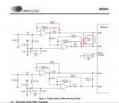
I've been spending a LOT of time at home the past few months, to while away the hours I decided to work on another update to PhiDAC. This new design in its first prototype form was named 'PhiDAC Quad' but is now 'PhiDAC Hex' and will hopefully be available in kit form during May. Its a two PCB design with a DAC-I/V board as the base and a passive filter board as a 'hat'. The key enhancements are that the passive filter is more complex to give better rejection of DAC imaging components and the analog stage has been upgraded by using opamps with external classA output stages. The filter 'hat' board will initially be supplied fully built and tested as the inductors and capacitors need to be close tolerance, checked with an LCR meter. Sound quality is I feel a significant step up over PhiDAC SE, in particular the higher frequencies are sweeter and there's more ambience/bloom.

The schematic can be found here : lingDAC - cost effective RBCD multibit DAC design

Update, October 2019

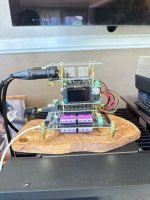
This thread was originally created to talk about lingDAC which is a stack of four 5*5cm PCBs comprising a multibit DAC based on two TDA1387s which is able to drive some moderate impedance headphones directly with up to 2VRMS output. The fourth (power supply) board isn't shown an an early picture nor in the earliest BOM, it was added during the course of the thread.

Prior to the establishment of the thread, a few 1st generation lingDACs (v1, the first generation having just 3 PCBs in the stack) were sent out to interested parties for listening reports.

LingDAC has at least one feature which make it a bit hard to DIY, especially for those with little experience. That being the filter requires fairly accurate inductors which necessitates an inductance meter being used to select 'good' ones from a batch. Or the filter's capacitors can be tweaked in value to match a slightly off-value inductor, this calls for simulation skills in Spice and a capacitance meter, again not really amenable to beginners. Because of this major drawback I decided to create a design more suitable as a starter DAC, this being called 'PhiDAC'. PhiDAC is introduced in post #126, December 2018 : lingDAC - cost effective RBCD multibit DAC design

PhiDAC has a much simpler single stage filter based on a large number of MLC inductors and only occupies a single PCB, 8*5cm. Instead of discrete transistors it uses AD8017 CFB opamps for its active circuitry. It calls for a single rail PSU of 9V-12V. This is a DAC rather than a DAC-AMP, its not designed to drive cans. PhiDAC was designed with components cheaply available on Taobao and hit a BOM cost just below $3 - some packs of ten kits were sold to interested builders.

The last design, PhiDAC SE rectifies this last weakness - its essentially the same circuitry as PhiDAC but using AD815s in place of AD8017s. The greater thermal capacity of AD815s means a much bigger physical package so the PCB size grew to 6*10cm and needs a single supply of 12-15V. The board doesn't contain the necessary electrolytic decouplers, they are mounted beneath on smaller auxiliary PCBs called 'pants' (opposite of 'hats'). PhiDAC SE hasn't had a complete release of all manufacturing information nor have I costed it but I'd guess it would come in around $5 with Taobao-sourced components. Here's a link to where I formally introduce it : lingDAC - cost effective RBCD multibit DAC design


Towards the end of the thread I'm doing experiments on using multiple paralleled DACs (given they're so cheap it seems an obvious route to explore) and eventually settle on a way to exploit them successfully - but the gory details of that journey will go into another thread. I'll include the link here when that thread's opened : Grossly parallel multibit DAC adventures


Original post, July 2018

I've been working on DAC designs using TDA1387 for several years now, both in helping modify existing designs and coming up with my own solutions.

'lingDAC' has satisfied me in listening to such an extent that I feel its worth sharing the whole design here as I feel I'm close to reaching the end of the road with what's possible when beginning with the TDA1387 (famous last words!).

A few bullet points to introduce this DAC :
  1. designed for Red Book CD source material hence 16bits and 44k1
  2. no-oversampling design means no digital filter is used
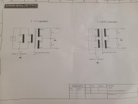
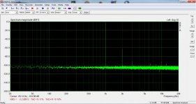
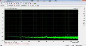
  3. a steep analog filter is used instead of the digital filter to kill images
  4. the design is aimed at reaching the best SQ, not best measurements
  5. lowest possible BOM cost commensurate with still sounding good
  6. designed as a board stack for maximum DIY flexibility, boards are 5*5cm

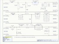
I need to tidy up the schematics before posting them, I'll add them to this post as they're rendered presentable.


Returning later I see I'm told I'm unable to add attachments to this post so guess new info will go into subsequent posts.

@kokoriantz has collected together pdfs of schematics - for lingDAC here (3 boards) : lingDAC - cost effective RBCD multibit DAC design and for PhiDAC (single board), here : lingDAC - cost effective RBCD multibit DAC design

USB to I2S : For Small Space .

Anyone here from Savitech Taiwan or Cmedia .
I am getting mad for months now . Most flagship smartphone started removing 3.5MM headphone jack . Most USB Type C adapter's are **** or good ones doesn't push enough power even into 32Ohms cans .
Savi Audio has lots of solutions but they removed their usb audio page .
Datasheet are scare . Even if I had to sign a NDA I don't mind

I looking forward to help . Anyone here knows any small MIPS processor with built in ROM

Threshold S/550e to SA/4e conversion?

I'd like to try converting the S/550e class A/AB to an SA/4e class A.
My understanding is that it's easy to do. These amps are the same -- just different power supply voltages and bias settings.

I have an operating manual for the S/SA series. I know the values for the inital bias settings for the SA/4e and that's easy to do. I don't know the required secondary output voltage for the transformer or the power supply.

Could someone share:

1) Which secondary taps to use & the desired PS output voltage?
2) Confirm that the bias settings & PS voltages the only differences?

I'm using this as a subwoofer amp and don't think I need all the power I've got. Not sure what the ohm value is for the subs but I'd guess I'd still be ok power wise.

Thanks Barry

Run 6X5GT or 6BY5GA Rectifier

My preamp uses a 6X5GT rectifier and wanted to know if I could wire the preamp to also run a 6BY5GA? Reading the data sheets it looks like I need to tie pins 3 and 4 together to have a connection to plate #2 (pin 3 on the 6X5GT and pin 4 on the 6BY5GA), and pins 1 and 8 so cathode #2 on the 6BY5GA is connected. Based on this it looks like I could switch tubes with no problem.

For Sale Denon POA 800 stereo mono power Amplifiers " two units"

1720111133981.jpg


Loking here for a new owner, asking price is 390€ for both units.
I have here for sale this amplifier in perfect working condition and in great visual aspect.
Everything is working just fine.
Any question feel free to get in touch.

Specs:
Power output: 50 watts per channel into 8Ω (stereo), 120 watts into 8Ω (mono)

Frequency response: 1Hz to 100kHz

Total harmonic distortion: 0.008%

Input sensitivity: 1V

Signal to noise ratio: 120dB

Speaker load impedance: 4Ω (minimum)

Dimensions: 434 x 120 x 300mm

Weight: 6.8kg

Attachments

  • 1720111035553.jpg
    1720111035553.jpg
    319.3 KB · Views: 83
  • 1720111081730.jpg
    1720111081730.jpg
    303 KB · Views: 67
  • 1720111081743.jpg
    1720111081743.jpg
    299.2 KB · Views: 68
  • 1720111174150.jpg
    1720111174150.jpg
    298.6 KB · Views: 106
  • 1720111247222.jpg
    1720111247222.jpg
    380.8 KB · Views: 91

WM8741 BASED DAC

Hi,

I'm looking for a dac based on the wm8741 chip and I saw that Weiliang developed several circuits, but I can't find any for sale.

Does anyone have an old PCB or can you tell me where to buy one of these dac boards with the original WM8741 chip? I intend to build this dac with tubes output stage instead of opamps, based on Lampizator circuits.

Thank you guys for all help

@weiliang

Thank you very much!
Nilton

ROTEL RQ-970BX Phono Preamp AD743KN 8DIP Upgrade Opamps

New (NOS) Analog Devices AD743KN FET Opamp from a bonafide USA distributor. 8DIP package. 2001 datecode. Still an excellent performing opamp for MM phono preamps like the Rotel RQ-970BX. Selling off old shop inventory. $9.75 each plus shipping. The USPS is not allowing on-line international postage purchase for small parcels like a padded envelope so it will be necessary for me to go in person.

looking for the song "Flower of Scotland"

Maybe anyone know where to find this song, it was on youtube on a NBR high res compilation. Female singer. It may have been on a compilation from another youtube chanel...i believe it was this url: [HQ Music] - The Absolute Sound - Best audiophile music collection 2018 - TD Media - YouTube sorry for not having more info. All i rember it was quite "ethereal", not the usual interpretation.

Midrange to range 200-2000 Hz?

Hi to everyone.
Need midrange in this range.
High SPL, nice sound and low distortion.
I have got pair JBL 660 GTI. Very low THD in 200-2000 Hz I see in review.
But I also saw a couple of other candidates
AE TD6M
Purifi PTT6.5M04-NFA-01

Purely theoretically, based on their high price, I will introduce a couple more candidates.
BLIESMA M142T-6
Accuton C168-6-990

Eico ST40

http://w3.uniroma1.it/chemo/image/hifi/st40-sche12-a3.png

I am only getting 12.5 watts out of each channel (10Vrms into 8 ohm resistive load), I tried replacing the cathode bypass caps for the 7591's and that didn't help. I got 405 on the plates and 360 on the screens, bias 14v at cathode and current draw all look fine.

This thing has old 7591 tubes, probably original. I tested them on my Hickok 539b and they test a little below min mutual transconductance. BUT I read here: 7591A tube comparisons That I shouldn't trust the Hickok for gm testing 7591's.

I don't want to fork over the dough for new tubes if I don't have to. I am thinking the low gm is causing the lack of power because the voltage is there and everything else looks fine, but that article has me reluctant to just buy new tubes. I am thinking somebody out there could think of other things to test. One thing is that all the capacitors are original on this unit. The orange wire from the output transformers are going to the 8 ohm tap.

Any thoughts are welcome please.

-bird

Aliexpress Dual AKM DAC Project - Problems Already!

Hi Everyone,
Just joined the forum. I'm building a dual AKM DAC using parts from Aliexpress and have already hit problems! It was this forum that gave me the inspiration to have a go, so hoping to find some help here. I'll post in the digital forums with pictures of the project and issues that i'm facing.

Nice to meet you all.
Cheers,
Andy

Transformer for F5 - 1 or 2 secondaries?

I need to order transformers for my F5. I planned to install two torodial transformers 320VA with one secondar 18V per trafo. Now I see that others are buying two transformers with two secondaries per trafo for dual mono and I don't understand why? What is the benefit of four secondaries instead of two?

Will 300VA 10A per channel be enough? I'm doing a custom order so suggestions are welcome

Greetings. Came across some Scan Speak Drivers, not sure what to do with them?

Kind of a long story. A golfing buddy of mine passed away - far too early. He was something of an audiophile and a packrat. His widow asked me to help clear out all his stuff. I ventured down to their basement and was amazed when I started looking in all the closets and boxes and bins of stuff. Hafner amps, Audeze headphones, etc. A lot of gear. I have spent a lot of time hooking gear up and making sure it works before trying to find a good home for all of it. Sold a bunch of stuff on ebay and raised a few thousand dollars for their Grandkid's college fund. His widow and I agreed that we did not want this stuff ending up in a landfill. My latest find is eight 5" Scan Speak 13M/8636-00 and four 8" Scan Speak 21W/8554-00's. They were packed carefully but not in their original boxes. They look brand new. I can hook them up and make sure they work, but would be surprised if they don't. So the questions is, short of embarking on a speaker build project (which I am considering), what do I do with them? What are they worth? If I were to sell, I would want them to go to someone who would build some speakers and enjoy them. I am going to do some research, but this site seemed like a good space to get some input. Thank you.

Elementary Noob Question of the Day: How tightly should you pack wool in an enclosure?

How tightly should I be packing wool into my enclosure?
I have this R15 cut in half (approx 2") and stapled to all the sides of the enclosure. I am leaving area behind the woofer to the port open with no packing material between those two.

I started packing in wool everywhere else inside the enclosure and quickly realized that I can lightly stuff it in there or I can jam it in there and fit 10x times as much inside.

I assume there is a happy medium here....? Should it just not be compressed further than how it comes out of the package? Should it be fluffed beyond how compressed it comes (I feel like it comes pretty tightly packed as it)

Attachments

  • PXL_20240711_133145418.jpg
    PXL_20240711_133145418.jpg
    385.4 KB · Views: 77
  • PXL_20240711_133146860.jpg
    PXL_20240711_133146860.jpg
    322.8 KB · Views: 76
  • PXL_20240711_133152800.jpg
    PXL_20240711_133152800.jpg
    426.4 KB · Views: 77
  • PXL_20240711_133154503.jpg
    PXL_20240711_133154503.jpg
    324.7 KB · Views: 78

I couldn't find the Target Function for this design

I'm experimenting simulating the conversion of 3 ways to 3.5 ways speakers. The objective of this experiment is to arrange the FR in a concept of integrated subwoofer speakers. I started by having a 3 ways speakers with typical 3 drivers; one tweeter, one midrange, and one woofer. Then, I'm going to add a second woofer to the system where the second woofer has its own cabinet.

The problem is I don't know the Target Function of the 3.5 ways speakers since I've never seen it before. I don't know what the ideal FR of the goal should be. So, I'd like to ask experts here for the criteria that would be recommended.

However, I have randomly tweaked the circuit myself. For the 3.5 ways conversion, I doubled the value of the inductor and halved the capacitor of the first stage crossover, and, doubled the second stage inductor again referred to the first stage.

Here is the original 3 ways system:
original 3 ways.png


Here is the modified 3.5 ways:
modified to 3.5 ways.png


Here is the simulated impedance plots of the two cases for comparison; blue dotted line = 3 ways, black solid line = 3.5 ways:
Impedance.png


I'm quite uncertain if it would work. Therefore, please advice me whether I did it correct or not.

PS. I know it should be done using actual measurements, but this is for research purposes.

Audiostatic ESH100 bias measurement

A few years back I bought a pair of Adiostatic ESH100 speakers. A hybrid set of a conventional woofer for the low end and an electrostatic panel for the mid a high spectrum. I did a restoration job, you know reglueing and refoiling the electrostatic panels and fresh paint. When I powered them up I was really satisfied with the result achieved.
But in longer listening sessions I found out that one of the stats was somewhat lower in volume than the other one. Forum member mattstat provided me kindly with several very useful hints. One of them was his advice to check the bias supply. Because life stood in the way it took me a year to pay attention to the audiostatics again.

I diy'ed this simple bias measurement tool (picture). A 1 Gohm hv resistor in series with a 1 Mohm one and double isolation. I don't expect exact measurements but for comparing and adjusting bias voltages it should be okay.

I couldn't find schematics of the ESH100 instead I found one of the ESH50 (picture). I also supplied several pictures of the inside and the electronics of the ESH100.

The transformer in picture 2 is the only one in this speaker.
Brown and blue wire at the left in picture 3 is 220V power.
Black wire with red tape in pic 3 is hv to foil.
Blue and red wire in this picture (top right) are connected to woofer filter.
The two black wires at the bottom of the pcb are connected to the stators. In the last picture it is easier to see that there are two black wires.

My question: to prevent doing something stupid I would like to know how and where to measure bias. For instance where to attach the ground clip of my hv probe ? Should I measure with or without connected esl panel ?

Attachments

  • es50_schem.pdf
    es50_schem.pdf
    39 KB · Views: 188
  • LD_IMG_2229.JPG
    LD_IMG_2229.JPG
    195.5 KB · Views: 304
  • LIMG_2386.jpg
    LIMG_2386.jpg
    122.5 KB · Views: 306
  • LIMG_2387.jpg
    LIMG_2387.jpg
    110.6 KB · Views: 306
  • LIMG_2394.jpg
    LIMG_2394.jpg
    89.3 KB · Views: 310
  • LIMG_2391.jpg
    LIMG_2391.jpg
    124.7 KB · Views: 299
  • LIMG_2388.jpg
    LIMG_2388.jpg
    110 KB · Views: 202

Fisher 400 and 500B Amps

The Fisher 400 and 500B (not 500C) are the most interesting amp I heard. They sorely need upgrade to Russian K40Y-9 caps including the tone controls and the one per channel damn ceramic cap in the audio chain. These amps (receivers) are far from the most clear sounding even after the upgrade, but the most pleasing amp on Rock & Roll. Live recordings are not placing you in the first 6 rows of seats, but at the 20th seat or so from the stage. The reverberation is just outstanding. You cannot hear this well on a stock Fisher 400 or 500 receiver. For some reason I am just mesmerized by the sound of these amps on rock and roll. They sound good with cheap Chinese 12AX7WA too.. I owned about 30 rebuilt vintage amps, none play as pleasing as these Fishers. Not for classical music, but best on hard Rock & Roll. Scott makes cleaner sounding amps, but not a Fisher My 2 cents.

Do I miss something in my crossover here?

Hi guys. I am new to speaker building. After doing some reading here and there, I decided it’s time to start making my first speakers.

My plan is to make a 2 way speaker, 1 tweeter and one midrange. I picked the drivers and designed my crossover with the knowledge I have. The SPL is traced from seller spec sheet. I am not ready for measuring equipment yet. I think it looks alright. Anyway, I am not sure if I miss something important.

Can someone share me some thought here? I understand I will need to tune it down the way. I’m just afraid I make some mistake that ruin everything from the start.

Thank you.

IMG_2226.jpeg

Building a center channel to match SRX812Ps

Hello -- I am Seth -- I posted this already in the new members area, but I don't think that's the right area for this -- I have an unconventional home setup (using JBL Pro speakers).

My man lair serves a triple purpose -- gym area, desk area, "theater" area. In the cinema portion, I have two PRX712s (which will eventually be SRX812P) and two SRX828Sps underneath for thumping (and boy, do the thumpers in Dune sound thumperin').

Basically, I'd like opinions on a center channel -- I'm still learning how all of this works -- but, I was hoping to be able to replicate the SRX812Ps. Basically, take the 2432H compression driver and sandwich it between two 2272F 12" drivers. A bigger box to compensate the additional woofer, and bam, massive center channel for my massive LRs. Basically a PRX825 but with 12" drivers on either side. (Don't ask me about side and back surrounds yet -- I have no idea what to try there)

But, yeah, I'll post in the appropriate forum for advice -- but feel free to comment here if you'd like.

(I've also considered going the way of a VTX V style design -- I'm still looking for ideas.)

What I'm hoping my equipment list will be in the end:
-SRX812Ps for LR (currently PRX712s)
-SRX828SPs for front subwoofers (there's not room for them anywhere else to even check if they sound better -- but that's alright -- they sound pretty great so far)
-Denon x3800H (coming tomorrow)
-Some bluray player -- most likely the mid-level Panasonic ($400 pricepoint, whichever that is)
-Sony X90L 65" (will be getting soon)
-Custom center channel to match LR
-Side and back surrounds (eventually)
-Possibly a 24" HS24 subwoofer for below 35hz -- we'll see . . .

Image: And yes, I know r/tvtoohigh or whatever -- the tv mount was here when we bought the house -- haven't moved it, don't know if I'll have space to move it, we'll see.

manlair.jpg
Projects by fanatics, for fanatics
Get answers and advice for everyone wanting to learn the art of audio.
Join the Community
507,616
Members
7,879,733
Messages

Filter

Forum Statistics

Threads
405,849
Messages
7,879,733
Members
507,616
Latest member
TheSwiftGuy