Thoughts on this? With an Active filter on my low woofers at 200Hz (2nd order buttworth) the roll off is smooth. When I use a low dcr coil (and capacitor) to mimic the 2nd order slope I get a boost in the 60-120Hz region that isn't there naturally. Using a higher DCR coil mitigates this but I'm wondering if someone can shed some insight on why this is happening. It seems to have something to do with the Q or "knee" of the filter. The speakers are GR Research M165 (16 ohm) run in parallel to give a nominal 8 ohm load. I have seen this happen with other speakers though. I have attached the measurements.

Do you have the schematic and component values of the filter? Is the woofer driver impedance interacting with the filter?
That's the next step to look at. The filter is a 5.6mh inductor and 100uf capacitor to make a 2nd order low pass filter. Pretty standard stuff. The rise in frequency is above the resonant frequency and below the filter frequency. It levels back out if I put a resistor in line with it. But who puts a resistor on the low woofer circuit in a crossover??????
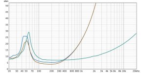
Here are 3 impedance measurements. Green is the woofers in the cabinet without any circuit. Brown is the 2nd order high pass filter. Blue is the 2nd order high pass filter with resistor. It makes sense why the circuit without the resistor would Boost the 60-120Hz range since it goes down to 4ohms in that area which will increase the energy there.
Attachments
What I can't do is get the impedance measurement of the filter when I'm using a minidsp since it's active.
I’m not able to take a close look at this at the moment, but I’m not sure about this statement.It makes sense why the circuit without the resistor would Boost the 60-120Hz range since it goes down to 4ohms in that area which will increase the energy there.
For one it’s likely the response is flat in general and the lower impedance is just an are outside the resonance. Putting that another way, the lower impedance isn’t supposed to suggest increased output.
The resistance on the other hand might get mixed up in attenuating the response according to the impedance variations.
The lower impedance isn't supposed to suggest higher output in general, but when the impedance is lower in relation to the rest of the impedance, it does mean higher output (more sensitive speaker). And that is what I'm seeing. You take a baseline impedance and frequency response that goes with it. When the filter is in place the impedance of the region 60-120Hz dips from 7 ohms to 4 ohms then you're going to get a rise in magnitude over that region. It doesn't happen with a higher DCR coil or when I put a resistor (of the same value as the higher DCR coil) in line. And this is correlated in the impedance measurements. The problem with the rise of the 60-120Hz region is that it really becomes a much less flat frequency response speaker and doesn't sound good at all. It masks everything lower and higher than that and the bass sounds floppy.I’m not able to take a close look at this at the moment, but I’m not sure about this statement.
For one it’s likely the response is flat in general and the lower impedance is just an are outside the resonance. Putting that another way, the lower impedance isn’t supposed to suggest increased output.
The resistance on the other hand might get mixed up in attenuating the response according to the impedance variations.
This is one argument in favour of an active cross-over - that the passive crossover has to cope with the impedance variations of real drivers to perform well.
This advantage is item 20 in the list of advantages of active crossovers in Douglas Self's "The Design of Active Crossovers" (!). He lists 22 advantages, 9 disadvantages and 6 illusory advantages - pretty thorough. Some sort of LCR resonant circuit in the passive cross over could compensate for the driver's resonance and cancel the peak properly - just lowering the Q is likely simpler and better in practice.
This advantage is item 20 in the list of advantages of active crossovers in Douglas Self's "The Design of Active Crossovers" (!). He lists 22 advantages, 9 disadvantages and 6 illusory advantages - pretty thorough. Some sort of LCR resonant circuit in the passive cross over could compensate for the driver's resonance and cancel the peak properly - just lowering the Q is likely simpler and better in practice.
I'm going to disagree based on the fact that it depends on both the mechanical and electrical properties. Mechanically, the speaker is moving into it's fundamental resonance there, and the impedance peak is a representation of that. The higher impedance is related to the reduced current needed for the same output.when the impedance is lower in relation to the rest of the impedance, it does mean higher output (more sensitive speaker).
Yeah, fair enough. But I enjoy designing passive crossovers more than active. I always start with active filters and move to passive, but this is all just for fun. If I really wanted to get the most possible out of designs then I think they would pretty much all be active with FIR filters.This is one argument in favour of an active cross-over - that the passive crossover has to cope with the impedance variations of real drivers to perform well.
This advantage is item 20 in the list of advantages of active crossovers in Douglas Self's "The Design of Active Crossovers" (!). He lists 22 advantages, 9 disadvantages and 6 illusory advantages - pretty thorough. Some sort of LCR resonant circuit in the passive cross over could compensate for the driver's resonance and cancel the peak properly - just lowering the Q is likely simpler and better in practice.
I think I simulated an LCR resonant circuit and the capacitor needed was something like 1,400uf so I just laughed and moved on. The problem with lowering the Q is that the slope of the low pass filter is correct. If I lower the Q then I get a much less steep slope (more like a 1st order) and that isn't going to work with the design. Ultimately, I'm using two 20 watt resistors and it evened it all out. Yeah, that's a strange move for the crossover, but I'm not actually losing any sensitivity and the frequency response is really flat so I'm totally fine with it. I matched the frequency response of the active filter this way so I'm happy with it. I can also remove the resistors and use a higher DCR coil there but I would rather just use what I have in stock since the results are the same.
Let me rephrase my statement on impedance. When the impedance is lowered in a certain frequency spectrum due to the filters added, it is making the speaker more sensitive in that region and therefore allowing for higher output in that region. That correlates to my frequency and impedance measurements. So, it's al about the impedance changing from its baseline in relation to the rest of the frequency spectrum. The 2nd order low pass filter using a low DCR (toiroidal) Inductor lowers the impedance of the 60-120Hz region down to about 4 ohms. That region stays around 7 ohms with a higher DCR coil (of the same value) and I assume it's around 7 ohms with the active filter since that's the baseline impedance in that region and the active filter shouldn't change that. The frequency response follows suit and the magnitude rises about 3db in that region with the low DCR coil. It seems that this is due to the Q of the capacitor in shunt (80uf), but the slope of the low pass matches the active filter perfectly so if I try to change that filter (and believe me I tried many different combinations of capacitors and inductors) I am unable to replicate the 2nd order slope of the filter properly without a higher DCR coil or resistors in line or a rise in that frequency spectrum. And the rise in magnitude from the baseline measurement is what caught me to begin with. I'm getting 3db more output in that region with the passive filter than I would get without any filter so I just thought that was strange to put a filter on and INCREASE the output, but clearly I had something to learn here.
Sometimes...When the impedance is lowered in a certain frequency spectrum due to the filters added, it is making the speaker more sensitive in that region and therefore allowing for higher output in that region.
Would you consider posting your response, impedance and target files so others might attempt it?
I think to do low XO points with passive XO, you need to do the main resonance impedance correction on the woofer.
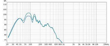
Definitely in this case. But again, it's clearly the Q of the filter causing it. I lost some of my measurements, which happens when I take as many as I have in the last few days so I couldn't export them again. But I have some export pictures of them here. You can clearly see the rise in magnitude of the one frequency response over the other, which is the passive filter gaining almost 3db in the 60-150Hz range in these 2 measurements. In the impedance graph, you can see 3 measurements. The green is a raw unfiltered woofer impedance. The brown is with a 5.6mh inductor in series and 80uf capacitor in shunt (for a 2nd order low pass filter). This is the same filter as the frequency response graph that gains the 3db in 60-150Hz. The third impedance measurement is the blue where I put a resistor in series before the inductor and the frequency response then matched the passive filter so it reduced the 60-150Hz region back to where it belongs.Sometimes...
Would you consider posting your response, impedance and target files so others might attempt it?
Attachments

- Home
- Design & Build
- Electronic Design
- Help-Boost in Low End from passive crossover? Why?