Considering amp design using 3D21WB

I'd like to generate a pp tube amp design in the 30w to 60w range using materials on hand if possible.
Have some 5k ct output transformers coming this week. Have an assortment of amplifier tubes, but I wonder if it makes sense to use these new 3D21WB tubes I have, most of the other tubes on hand are used. Does anybody have any insight how to set up bias on this tube? I'm a newbie, and the tube is a 40 watt dissipation tube, I see load line charts with variations of G1 and G2 connections. Seems like I can get decent power, but also appears the voltage has to be pretty high, also the plate current, so I imagine the idle power would be atrocious. Thoughts from the experts?

Building a speaker around a 6cu ft enclosure

TL;DR:
I have some big empty 6cu ft. enclosures.
I want to bring them to life in some capacity. Ideally to experience the "aliveness" of efficient drivers in big reflex enclosures.
I'm not after perfection. Here to have fun and learn something through experimentation and this community.
I'd like to keep it under $1k USD.

Long version:
I fell into some speaker cabinets that likely started their life as DIY Altec A7 enclosures and more recently were refurbished as a 515B / 802D combo by the person that gave them to me.
Here's a photo of the before and after. Note that I only have the cabinets. No drivers, horns, xo's etc.

hYvbKZc.jpg
2g62a04.jpg


I took some measurements and made a drawing to calculate net volume:

Screenshot 2024-06-06 at 12.45.11 AM.png

External dims are 36x24x15"
Gross internal volume 6.21 ft³ / net (without driver displacement) ~6 ft³

So now the question is, what can I do with these?

My only real requirements:
$1k USD budget
Limit woodworking to small mods – baffle changes, bracing, etc.
I want to build something high efficiency to pair with my Amp Camp Amp or Fisher 400, but I also have some 100W Class D amps available if I go the DSP route.
I'm fine with soldering but have no experience designing crossovers.

The more subjective stuff:
I'm "horn curious" – I love the way they look and I'm wondering if there's econowave projects that might be a good reference here (though I haven't seen any 6 ft³ builds yet..).
One thought is that enclosing the horn in the cabinet will eat up some volume and get me closer to some of the 5 ft³ e-wave projects (or the 4pi, etc.)
I'm open to DSP – and I'm thinking that could be a good way to learn about crossover design and room dynamics.
I'm assuming I will need to cut a new baffle – both for speakers size and for port tuning.
From a budget standpoint, these Lii Audio 15" coaxials are attractive – even includes a crossover.. but the T/S params are confusingly lost in translation.

What would you suggest?
  • Like
Reactions: grindstone

Onkyo DX-7333 schematic/service manual

Hello,

I have an old Onkyo DX-7333 which I just bought 2 weeks ago. At first it did not recognize discs at all, or was very picky when it did so I decided to change the whole laser assembly which resolved the issue, it plays fine everything.

Before that happened and I could listen to CDs and even after the laser assembly was changed every CD I listen to has a mild distortion in the analogue signal path - headphones and RCA out (SPDIF is perfectly fine).

I'm wondering if anyone has a schematic for this particular CD player, or service manual.

I'm a newbie but I would like to fix this issue. However I wouldn't want to start swapping out components one-by-one without understanding the insides at first. I couldn't find it on the Internet.

Any help is appreciated.

Best Regards,
Márton

Sony STR-DH770 doesn't power on

Hello!

I have a Sony STR-DH770 amplifier, which sadly doesn't want to turn on anymore.

The way it happened was very dumb, as I was reorganizing cables and so on, when I was plugging it back, seems like some dust/particles got into the socket and when plugging it back in, it made false contact a couple of times, cause I heard the relay click a couple of times, and afterwards it did not want to turn on anymore.

Checked the fuse and changed it, but it made no difference.

Whenever I plug it in, I hear the click of the relay, so I have the feeling that the issue is the main transformer and the stand by transformer is still working, which is a is a similar issue as was posted here: https://www.diyaudio.com/community/threads/sony-receiver-wont-turn-on-need-help.167239/

I was hoping someone can enlighten me on how to properly test the transformer to know if this is the root cause of the issue, and changing the thermal fuse (if necessary)?

Greetings!

Attachments

  • IMG-20240718-WA0075.jpg
    IMG-20240718-WA0075.jpg
    268.5 KB · Views: 144

Techniques for creating non flat surfaces for enclosure internal walls fusion 360

Hey everyone,
I've worked on a few speaker enclosure designs and use 3d printing to create them. (Ignoring the issues with 3d printing a resonance for now, I've got a few ideas how to get around this).
But what I would like to do is create non flat internal faces as the printer should be able to make this easily. However, I do not know how to create these in fusion 360 or any other cad for that matter. Has anyone got any tips they could share?
Pics attached to try and get across what I mean. Doesn't have to be these patterns.

Thanks

Attachments

  • images (1).jpeg
    images (1).jpeg
    7.1 KB · Views: 71
  • images (2).jpeg
    images (2).jpeg
    5.6 KB · Views: 77

Denon DRA-F107DAB Reset every time power disconnected

Hi

New member so apologies if this the wrong forum.

I have a problem with my Denon DRA-F107DAB Amplifier - Tuner

Every time I disconnect the unit from the power supply the next use requires a reset before being used. When I disconnect the power, after turning the power off on the unit, there is a "click" from inside the unit.

I have tried different power cables and also tried it with the speakers disconnected.

Does anyone have any ideas what might be causing the problem or which component might be faulty.

Thanks for any help.

Canton CA20 Active speaker repair

Hi Experts 🙂
Hope this is the right section.
I have a couple of Canton speakers that has been with me for over 20 years now. The model is CA-20 witch is a fully active four way construction with one amp board for each driver including a cross over section custom for the that driver.

20221216_172432.jpg


In the past years I havnt been able to use them since there have been problems with clicking protection relays etc. All issues have be resolved now and all amp boards are amplifying signal within the frequencies they should on my work bench.

With their age and all (manufactured 1988) I have replaced all etyl caps in the PSU section and would also like to do so on each amp board.

There is a schematic but no other documentation. No text on PCBs at all. There are six pots on each amp. Could someone perhaps tell me from the schematic what these pot are adjusting? How do I set idle bias? Between were do i measure to get current bias mV? Most of them are in the cross over section so i'm guessing they adjust cut off frequencies etc?

This schematic, as an example, is the HT board, driving the Tweeter. (HP Filter) IC1 & IC4 are TL074CN
HT CA20.png
If I know how to set bias I can measure before and after cap replacement and then adjust if needed so I don't alter anything.

Any info here would be greatly appreciated as there is no info to be found anyware. Canton hasn't replied to my request for more service documentation and to be fair they are from the eighties so..

The sound awesome though!

I could not add the full schematic to this post but it can be downloaded here if anyone is interested:
https://elektrotanya.com/canton_ca-20_active_speakers_schematic.pdf/download.html


Thanks
Daniel E

Attachments

  • 20221216_172432.jpg
    20221216_172432.jpg
    356.2 KB · Views: 468
  • HT CA20.png
    HT CA20.png
    116.9 KB · Views: 659
  • Design.png
    Design.png
    38.1 KB · Views: 285

Volumio Rivo recommended!

I know it isn't DIY, but after a few iterations of diy digital servers with RaspberryPis, I got fed up with the continual maintenance. My diy interests were decidedly elsewhere, so I took a punt and bought a Volumio Rivo purely as a destination for Tidal connect. I have been using it to feed an ifi microDSD for about 6 months now and LOVE the "just works" nature of it. Setup sounds great to me too. If anybody out there is looking for plug and play level Tidal connect streaming, I wholeheartedly recommend the Rivo. The guys that sell it out of Italy were responsive and generally great to deal with as well.

Tantalum capacitor recognition

Hi all, I am in the process of rebuilding and finalising the choice of replacement capacitors in my naim 32.5 pre amps and wondered if anyone knows what these little dark Orange Tants might be ? They measure lower ESR than Kemet 356 and the old used Panasonic blues, and they sound the best doing A-B, I even checked by swapping them from one board to another (Thankfully naim don't bend the legs to make removal more difficult !)

All 10uf 25V, Any ideas ? the Panasonic Blues measure 10-11uf and ESR of 600-700, the new Kemet's 9.5-10uf and ESR of 600-650 and the Orange 10-10.5uf and 500-550 ESR, but they sound better than the others doing A-B tests

IMG_1213.jpeg

IMG_1214.jpeg

IMG_1215.jpeg

Cumbbs Koans

A tiny power follower?

My curiosity was awakened by some posts in the JLH 10Watt class A amplifier thread. Member cumbb had posted a few photos of modest point to point creations declared to allow for a pleasant listening experience.
Other members appeared to be curious as well, but despite requests, a detailed circuit does not yet appear to have been revealed.

For the educated it is likely no challenge to figure out the circuit. But for myself without anything other than very basic knowledge in electronics, it will serve as a healthy brain exercise to figure out the circuit based on info from photos and enigmatic posts.

I started this thread to avoid filling the JLH-thread with off topic material while trying to figure out a working circuit.

=> Mr cumbb, if you in any way dislike or oppose to this thread or posting the circuits, please let me know and I will ask the Moderators to remove this thread immediately!

Post #4069 in the JLH-thread Mr cumbb post one of the first photos:
1672560858332.png

From this photo and from other photos in posts #4120 #4388 #4421 #4560, I am trying to dumb-luck myself to figure out a working schematic. The iterations evolve throughout the JLH-thread and post #4560 shows a called balanced version which would be the final objective to figure out.

Starting with the initial creations from the first photos, I have so far tried with the circuit below. Even being significantly uncertain of component values it is actually producing music on a test speaker. Was not able to bias up to suggested 1A with 12V so will try to experiment further prior to testing on a better speaker.
1672563444950.png


Appreciate anybody's constructive suggestions and I really hope the creator himself, Mr cumbb will assist in resolving this matter.

Let's see how it might develop.🙂


❤️Disclaimer: This thread is started is started in a positive spirit only. If the content would awaken any primitive impulses or negative emotions within you: Please swiftly press the "go back" button in your device and you will moved away from whatever that aggravates your lesser evolutionary functions.❤️

Attachments

  • 1672562557331.png
    1672562557331.png
    12 KB · Views: 344
  • Thank You
  • Like
Reactions: cumbb and huggygood

HD-15 Kick Bin Horn Design

HD-15 Kick Bin Horn Design

I am in possession of an unknown, unloaded speaker cabinet and an Eminence Delta-15LFC driver.
https://www.adamhall.com/shop/bm-en/archiv/2510/delta-15-lfc

The internal measurements of the said enclosure box are very similar in dimension to the outside measurements of a HD-15

Outside dimensions of a HD-15 - 578 x 578 x 472

Inside dimensions of 16mm MDF donor cab - 580 x 510 x 480

Most measurements are close enough but I want to make the horn longer and with a different radius.
I sketched out a quick box and horn with a radius of 500mm...... Attached below

Will this suffice....? Am I on the right track here.....?

HD-15 Horn.jpg


20240730_125255(0).jpg


I also read that I can reduce the volume of the driver chamber to make things a little more efficient.
Something like this
------>

HD-15 Driver Chamber Volume.jpg

Repair tips JL Audio JX500/1

I have a JL Audio JX500/1 that had the power supply mosfets and a couple of BJT transistors damaged, I replaced all of the for brand new components, same batch, the transistors replaced were:


8 RFP70N06 (not sure if those are the original ones, it looks like those were replaced at least once before)

4 TTC5200, original ones were from toshiba, but I bought brand EVVO, I got them from digikey

4 TTA1943, original ones were from toshiba, but I bought brand EVVO, I got them from digikey


I checked the fets driver TL494CN with a scope, it is working fine, after that, I turn the amp on and it changed from protect to power mode, I connected a subwoofer and it looks like it is working fine, but after around 10-15 mins working, the output stage section is heating up very fast, power supply stage is very stable and is not hot, I decided to turn the amp off before it gets damaged again.


The output driver transistors used in this amp are the TP41 and TP42, I don't know if those are the originals or were replaced before, in some threads I read that these transistors are not good as drivers, do you know if these transistors are the original ones used by this amp?


what can be causing that the amp is heating up very fast only in the output power transistors (C5200 & A1943)


I really appreciate your help.


thank you

Retrofier Labs

My latest project is out on Reverb.com and it's been a very fun and inspiring one indeed.

A few years back I was doing quite a bit of repair work and learned that the region of Washington state were I lived at the time lacked anyone with my audio electronics skills or at least ones willing to do repairs. This led to becoming the local music store repair guy and what an adventure that turned out to be. At some point a discussion with my wife led to the interesting idea of taking my favorite repairs, the vintage stereos, and turning them into a different sort of side job. For some reason Pioneer turned out to be my favorite and we found several specimens on ebay that were seriously ready for some love.

Then an interesting guitar effects pedal related collaboration came along and that put off the stereo project for few years but now I'm getting around to restoring those Pioneers with great care.

This SX-550 opened my ears well beyond what I thought it would. In fact, it's now become quite the friend in the office portion of my lab where my burn-in process for this unit ended up being far more extensive than I thought it would be. I'm not easy to please regarding audio and I can tell you that I love to power this one up every morning. I also discovered that an FM station in my area plays 70s music all day Saturday and that proved to be interesting. For the first time in a very long time I'm listening to FM again. Weird. I'm even listening to the few vinyl records that I still have.

The SX-550 is now on Reverb.com!
https://reverb.com/item/82314088-pioneer-sx-550-1976-brushed-aluminum-oak-veneer
02.jpg

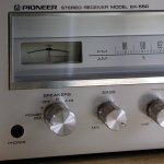
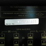
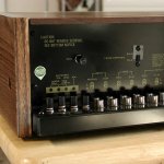
Pioneer SX-550 – Manufactured September 1976
Restoration by Retrofier Labs

The Restoration Details:

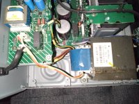
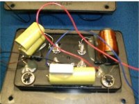
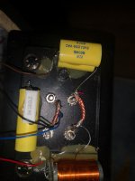
Complete Electrolytic Capacitor Replacement or “Recap” - This includes the substitution of several small value electrolytic capacitors with equivalent film capacitors for low distortion and reliability.

All Controls Cleaned and Lubricated - All of the potentiometers and switches were thoroughly cleaned and lubricated using air and Deoxit.

Solder Connections - The entire system was visually inspected and any suspect solder connections/joints were reworked.

Dial Cord Replaced - The dial cord in stereos of this vintage are often intact but slipping and making creaking sounds as they have lost their flexibility with age. The cord in this unit was replaced with a proper equivalent of the original and the pointer track was also lubricated for smooth and quiet tuning.

Tuning Control Shaft Assembly Rebuilt - The big knob with the heavy flywheel that gives the tuner it's 1970s feel is mounted on a brass shaft/sleeve assembly that often looses it's lubrication over time and sometimes completely seizes. It must be disassembled, cleaned, lubricated, reassembled, and carefully adjusted for the appropriate shaft end-play. This has all been done for this unit and it feels very much as it would have in 1976.

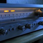
Dial Lamps Replaced - Quite often you will see old stereos with the lamps replaced with LED equivalents and that works, but I prefer incandescent lamps that give the vintage glow and maintain the original look as much as possible. The lamps I use run cooler and last longer than the originals and don't flicker or generate radio interference. Many of the original Pioneer lamps are are still working after nearly 50 years and the replacements in this unit can in theory run much longer.

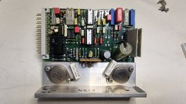
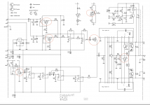
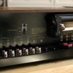
Power Amplifier restoration and upgrades:
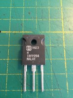
  • Transistors - The output and driver transistors were replaced/upgraded using much higher performance modern versions that significantly lower the distortion relative to the original specifications.
  • Stability Margin Corrected - The new transistors having more bandwidth and less capacitance than the originals means that the amplifier's stability margin must be corrected and the appropriate changes were made. The amplifiers are free of any high frequency stability problems.
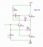
  • Bias Controls Modified/Corrected - For unknown reasons the original SX-550 amplifier bias trimmer rotation is reversed and they allow a far too high Vq voltage that results in a quiescent current that can lead to power amplifier failure. This maximum happens at the full counter clockwise and thus counter intuitive position. The necessary modifications were made to reverse and limit the trimmers to prevent future problems. This also protects the amplifiers from overheating should the trimmer potentiometer’s wiper become an open circuit from shock, oxidation, or contamination.
  • Amplifier Bias Set and Distortion Characterized - The power amplifier bias was set using a distortion analyzer measuring a worst case THD+N of 0.008% @ 1kHz with the output just below clipping and loaded with a non-inductive 8 Ohm resistor.
Note: The SX-550 is rated for 8 Ohm loads only and this is easy to violate with the A and B speakers on at the same time. Be sure that the total load is always 8 Ohms or more. It should also be noted that short circuits while signal is applied can destroy these power amps immediately.
The original SX-550 is rated at 0.3% THD @ 20 Watts and 0.07% @ 10 Watts. This rather high and inconsistent distortion was mostly due to the poor quality (by today’s standards) output transistors causing significant large signal distortion that has been removed from this unit using much higher quality modern devices and proper bias adjustment using a distortion analyzer. The sound is now very pristine.

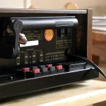
Power Switch Rebuild - The Pioneer SX-450 and the SX-550 had a rotary power switch that often developed arcing problems after many years of use and this caused behavior that can be very misleading as the symptoms suggest other problems.
The good news is that these were very well made switches that can be disassembled, cleaned, lubricated, and reassembled to end up with essentially a new switch. The contacts have generous material to be resurfaced and should last another 48 years. This unit's switch was not an exception and after the rebuilding, it works like new.

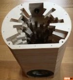
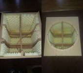
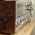
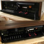
Real Oak Veneer! - The Pioneer SX-450 and SX-550 and likely others have metal top covers that are almost always like new. For some reason the material used to simulate wood for the top piece seems to last forever.
The particle board end caps are another matter. These are always in poor to very bad condition. My solution for this problem is to strip away all of the plastic material and refinish them with real wood veneer. This gives the end caps a truly "high end" and better than new appearance. I stain them to reasonably agree with the color of the top and and finish them off with water based polyurethane. This particular unit has Oak veneer and looks really cool.

Tuner Alignment Tested - The AM and FM tuners in the SX-550 use ceramic filters and what alignment is adjustable is rarely off. Nonetheless, it's good to test for any significant error and I do. This unit's tuner could not be improved by any adjustment and it sounds very good. All is well.

Headphone Output Recalibrated - The headphone output of the SX-550 as with most others of the era were designed for 8 Ohm headphones which today is not so common. Older stereos like this used a simple technique of dropping the power amplifier output with a resistor to get the headphone output to a reasonable level. The problem is that most headphones have much higher impedance these days and to complicate things further, there is no standard for headphone impedance(that I know of) and the range is pretty crazy at about 8 to 300 or more Ohms.

What I decided to do for this SX-550 is change the resistor to be ideal at the 64 Ohms of my Sennheiser HD 280 headpones which are very popular and sound very good. This is not to say that others will not work, it’s a matter of the volume level and with the range of the SX-550’s volume control there shouldn’t be problem for most headphones.

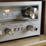
Cleaning and General Condition - The exterior of this unit was throughly cleaned but not altered in any way. All of the paint and brushed aluminum surfaces are original. All of the nicks, scratches etc. are very small and not generally noticable. Overall it's almost like new. The glass is in pristine condition and the black printed lettering on the front panel is incredibly free of defects. A very well preserved stereo that's nearly 48 years old.

Output Power - The SX-550 is rated at 20 Watts per channel @ 8 Ohms and it isn’t rated for lower impedances.

But how loud is that and what do you really need?

Where this Pioneer model is concerned I can share my experience because I use one every day. My SX-550 is connected to some nice but very inefficient bookshelf speakers situated a few feet away and I have carefully measured the output power under various listening conditions. What I discovered was that I use even less power than thought.
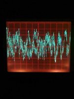
First I should point out that the only case where I might consume the entire 20 Watts of the SX-550 is when I hear a good song on FM or maybe want to play along with a song and crank it up a bit. The peaks in this case can get close to 20 Watts while the nominal or average is about 300 mW or 0.3 Watts. My perception of the loudness at this level is that I would not go this loud if I lived in an apartment and I’m talking about 5 inch woofers. It fills the room surprisingly well.
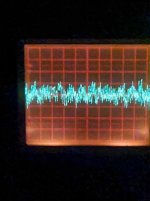
My general conclusion from these tests is that 20 Watts is plenty for my use and most of the time I only need 5 Watts for peaks, not 20.
This is simply an example based on my personal opinion to give some idea of what 20 Watts means in a practical situation at home with modest speakers. It’s really a very useful level of power and does not leave me wanting. With larger and more efficient speakers which also have more bandwidth, 20 Watts is more than enough from my experience.

Vinyl Record Playback? - The moving magnet preamp/EQ had it’s electrolytic capacitors replaced with film types and is now within specifications for the SX-550. By listening, it sure seems to work well. I played several records ranging from horrible scratchy things to wonderful clean specimens and they all seem to sound as they should.

What Did It Cost New? - In 1976 the SX-550 sold for $250.000 USD which in 2023 USD would be $1278.44.

Attachments

  • 01.jpg
    01.jpg
    536.4 KB · Views: 110
  • 03.jpg
    03.jpg
    221 KB · Views: 86
  • 04.jpg
    04.jpg
    546 KB · Views: 102
  • 05.jpg
    05.jpg
    575.6 KB · Views: 112
  • 06.jpg
    06.jpg
    460.6 KB · Views: 103
  • 07.jpg
    07.jpg
    457.6 KB · Views: 93
  • 08.jpg
    08.jpg
    578.1 KB · Views: 101
  • 09.jpg
    09.jpg
    537.9 KB · Views: 106
  • 10.jpg
    10.jpg
    781.5 KB · Views: 93
  • 11.jpg
    11.jpg
    634.9 KB · Views: 83

Listening to Classical Music with High End Hearing Loss

I can’t hear much above 4 KHz anymore. But I’m still enjoying classical music as much as can I remember in the past.

Except for the piccolo that can go up to 5 KHz, I can hear the full range of fundamental notes from all the other instruments pretty well. I’m probably missing some of the lower order harmonics from things like violins and the piano, although that doesn’t seem to be really very noticeable to me.

And since a lot of the music still resides below 2 KHz I don’t think I’m missing very much at all.

So, it leads to the question of whether single driver full range speakers would be even better than the current 2-way Piccolos that I have. That would get rid of the crossovers completely, although I not sure of just how much benefit it would bring.

I know there a lot of full range fans here, so I’m looking for anyone with similar experience that may have traded a quality sounding 2-way for a full range to play classical music and heard any appreciable difference or improvement.
  • Like
Reactions: oscroft and Drbulj

Best (or less worse) way to use two dissimilar pairs of drivers

I have four 4 ohm, 40 mm drivers I wish to use to make two vented enclosures for 200 Hz up (flat above 200, hopefully). Each enclosure would have 2 drivers plus a tweeter.

However, these four drivers are two separate pairs, and they're slightly distinct, one pair having higher Fs and lower Vas than the other, but the rest of the parameters (like Xmax, DC resistance etc) being much more similar.

I already have an amplifier to use with them, but it can only use loads down to 4 ohm (at least in principle). So I should wire them in series.

And, if I want the left and right side enclosures to sound the same, I should, in principle, use one of each pair in each side, so each side would have 2 dissimilar drivers.

But coming to think about it, I think this would probably not be a good idea either.

To begin with, even if I made a separate cavity with its own vent for each driver, the fact they're in series is still a complication. They have different impedance curves, and I can't simulate each driver as if it were in series with a simple resistance, it's in series with another driver, that's not mechanically coupled to it anyhow.

And WinISD at least can't simulate that.

I thought for one second about measuring the TS parameters of them in series like they were a single driver, until I realized this would only make sense if their cones were also mechanically tied together, always moving as a single thing.

Maybe, then I should make each side using one pair, and just try and tune them to be the most similar as possible? Their phase response isn't going to be the same though.

Plus, a small question: Do you know if, when using more than 1 driver in a WinSD project, it considers they're in series or parallel? There isn't an option for that, that "voice coil connection" option is for drivers with a segmented voice coil, not for the connection between the drivers. I'd assume it considers they're in parallel.

If it considers they're in parallel, it's a further complication, as, in the case of using one pair in each side, I'd still like to wire them in series.

What would be the best way to go about this?

Thanks!

Alternative approach to RIAA Phono

I've been taking a look at an alternative approach to RIAA equalisation that has been patented in the last few years (https://patents.google.com/patent/US20170126186A1/en) by Graham Slee. This basically equalises the pickup's constant velocity frequency response by putting an integrator as the first stage providing the 3180us pole (50Hz). This effectively provides a constant loop gain for that stage. The remaining 318us (500Hz) and 75us (2122Hz) time constants can easily be dealt with by a simple passive filter. My take of an MM phono using this approach is attached. I've include a secondary LP filter to address the non-inverting amp's roll-off at unity gain, a 20 Hz rumble filter and a simple flat gain stage with potential gain adjustments to allow for differing cartridge output levels. Overload margin is in excess of 30dB for a 5mV MM cartridge.

I've modelled the input stage with an OPA1656, a very low current noise/low distortion FET op-amp. Other suitable choices would be OPA1641 / OPA1642 or similar. As an aside, the use of a FET device as the input stage will also provide good RFI proofing.

This has been built and is my current phono amp in use on a regular basis. On a subjective basis, its clean, precise and provides an open sound stage. As far as measurements go, I've run a quick and dirty frequency response check using an HP3312A function generator, inverse-RIAA network and an analogue 'scope. This confirms the flat response across the 20Hz to 20KHz range. I also confirmed the overload margin.

Attachments

Service light blinking inside amp

My mtx7801 amp was running and voltage dropped below 10v
Amp stopped working. No power lights, no protection circut light, took amp apart and hooked up power and led 401 service light is blinking, no obvious part failure on board, where do i start testing.
I believe amp was repaired in past, cannot upload puc files are too big. Guessing its a fet attached to heatsink. Will link thread with pic that matches mine, explenation of whats going on?

Replacement thyristor

Hello guys I repairing my HP3632a power supply and need to find a replacement thyristor for CR28 on the schematic, it's a MCR264-4 , closest I can find on Digikey is a S4040RQ3TP .. I am quite new to the electronics hobby and have done quite well finding replacement transistors but some are a little more challenging and I could really use some help with this .. The problem I'm finding is knowing how far I can deviate from spec on a transistor ..

For Sale Onkyo FM stereo/AM tuner used in great condition

I am selling an Onkyo model T-4310R FM stereo/AM tuner used but in great condition, as you can see in the pictures below. Fully functional, no scratches or dents. I have both user and service manuals in digital format.
Asking US$80 paid via Zelle. I am willing to ship if buyer pays for the cost of both packaging and carrier. Alternatively buyer can pick it up in Huntington Beach, CA and pay cash.

Onkyo_T4310R_front.jpg
Onkyo_T4310R_back.jpg
Onkyo_T4310R_top.jpg

spray paint and wood grain?

Has anyone used spray paint on wood with the intention of keeping the grain visible?
What problems did you run into?

I am making bases for gem stone cutting machines so this is not furniture. When I got the contract was a simple stain and poly job.
Now the color scheme of the machine is being updated from
New-Facetron-Faceting-Machine-2024.png
to black on black. Black stain looks washed out and is hard for me to keep from being blotchy across the several applications to get a deep color. I can add pigment to the stain but in my mind I am just adding solids to the oil based stain, you know, i'm making paint that is a hassle to apply.

Why not just skip the hassle and use spray enamel?

I'm looking for critique . Why might this be a bad idea?

Jeremy

Is that really 8 Ohms?

My speakers are three-way system and the stickers at speaker terminals are labeled 8 Ohms nominal. However, I have measured the drivers’ resistances (Re) by a RLC meter and they’re shown as follows:

Tweeter = 3.2 Ohms
Midrange = 3.4 Ohms
Woofer = 3.6 Ohms.

IMO, these all should be 4-Ohm drivers.

So, why the manufacturer claimed they’re 8 Ohms nominal?

I know the speakers have an impedance curve which could be fluctuated depends on frequency. But the 8 Ohms nominal is the result of averaging with the peaks on the impedance curve, isn’t it?

Has Anyone Have Experience With This DX-45M SanKen 1494/3858 Amplifier Module?

Does anyone have experience with this Sanken Power Amplifier Module?

The only "name" I can find for it is "DX-45M" on the outside of the box.

I don't seem to find anything with a search for "diyaudio DX-45M" so hopefully it is ok to start a new thread.


I would like to try an amplifier with Sanken outputs to see how it compares to the K1047 based amplifiers I have tried. (MX50X2 & L20.5) After the comparison I might order some of the still available MT100 smaller Sanken devices from Digikey to try in my other projects.

It is described as "SanKen 1494/3858 High Power HIFI Audio Amplifier Board Dual Channel 450W+450W Stereo Amp Mono 800W Amplifier Board For Sound DIY"


It is attractive for me for a quicker project since the heatsink, power filters and speaker protection are all integrated.

If you have this amplifier please let me know what you think of it and if you would recommend I try it. Also if you have it do you have a schematic? Any idea of the internal amplifier structure/type? Such as Blameless or something else?


Also, has anyone more extensively tested and evaluated clone SanKen 1494/3858 devices? I ask since I would not be surprised if this came with clone devices. It is also why I would like to find someone who owns this amplifier and can offer their first hand experience.

Attachments

  • Sanken Stereo Power Amplifier on Heatsink.png
    Sanken Stereo Power Amplifier on Heatsink.png
    212.3 KB · Views: 386
  • Box With DX-45M Printed On Top.png
    Box With DX-45M Printed On Top.png
    119.5 KB · Views: 322
  • Amplifier Section.png
    Amplifier Section.png
    352.7 KB · Views: 312

Aggravated SONY TA-F444ESII ATTENUATOR/Volume control

I have an almost new SONY TA-F444ESII with ATTENUATOR issues.
In the times of old we would just rotate a few times to wipe it clean, however this sorta helps.
Even after the wiping one channel or both are either static or not there, a few more wiggles and things settle down.
Most times it will play all day with no issues.
Does anyone have a fix for this? I bought this guy in 1985 and have enjoyed it a lot.
Looking online has produced no parts or links this site was great to read for some other issues and how to check/correct.
I live in Southern Georgia and know of NO shop to contact. All help is appreciated
(And almost new is relative)
Thank You
wmildman

Slew rate of TDA2040

Does anyone know what the specified slew rate of the TDA2040 is supposed to be? I haven't found it in any datasheet, or anywhere else at the internet yet. The reason I wonder is because I just measured the slew rate of my old TDA2040 amp, and was just around 4 V/µs (!). No wonder it sounds worse compared to my other amps.

Could this really be right? 4 V/µs is a really low for a 25 W amp. I built the amp as suggested by the datasheet with a dual supply of +/-16V. One of my first projects as a teenager and thought it sounded ok then...

Crown 460CSL Fault - Full Short

Trying to repair a Crown Grounded Bridge 460CSL. This is a cut down/ cheaper variant of the Micro-Tech and Macro-tech. The Dim bulb is full brightness. Traced to one channel on high side.

Removed drivers and output devices on high side, switch on and short clears. All devices measure fine/no shorts. Installed with known good devices, Crown graded outputs and Sanken drivers from my spares, switch on and dim bulb full brightness. Removed drivers and dim bulb is dim!

Removed ribbon cable to high side and short clears!

Tried with a known good main module and the exact symptoms appear.

Removed op-amp from board and no short!

I'm at a total lost to why this happens.

Schematic is the Geodyne version (similar)

Attachments

Adding power off to existing amps

I picked up a Pass Labs X1 pre-amplifier and it has a 12 VDC "Amp Turn On" output signal. The manual specifies it handles 50mA max. Has anyone found a way to use this signal to turn on/off the external amplifiers that don't have this feature? I was thinking to insert a relay to close the power switch in the amps when activated. Alternatively, I could avoid modifying the amps and build switched outlets. I have two questions to ask:
  1. Is doing this a bad idea?
  2. What relays and/or circuit should I use?
    The relays I found either don't provide any current specifications on the DC input at all or their rating is too high (~48mA per relay).
Thanks.

For Sale Scanspeak 18W/8545K00 Carbon 7 Driver in Excellent Condition (Fritz Speakers)

IMG_20240805_125437_704.jpeg
IMG_20240805_125448_781.jpeg
IMG_20240805_125605_360.jpeg
IMG_8460.jpeg
Excellent condition, bought it old new stock from Fritz of Fritz Speakers. He used them in Carbon 7s speakers. One spare driver is left and is for sale. I know that 18W/8545 retail for $240 each or more if you order then in Europe with shipping they are $300 each.

See the pictures it is in excellent condition, it was stored properly (cone down). You can see resistance measurements on my multimeter.

$75 shipped in cont. USA

Alpine SWR-1542D - What is it good at

For few years I have Alpine SWR-1542D. On paper it looks nice but so far I am not impressed.
I have it in my car and have it paired with Hertz ML Power 1 amp. 1542D has RMS 750W and I was pushing 1000W with the amp, no problems.

As it's a 15" sub, it's a bit on the bigger side but I wanted a sealed enclosure anyway as it's simple to make and I wanted to focus more on SQ. I made a sealed enclosure recommended by the Alpines manual. Which was ~46L net volume. Big mistake as it is underwhelming.

This is what I built:
JwRmt9N.jpg

2e65AxA.jpg


Odd shape shouldn't be a problem?
Anyway with Qtc at 0.806 it should have fsc at 43 Hz. And this is what the transfer function magnitude looks like with 18 Hz 24 dB/Oct highpass filter and 120hz 24 dB/Oct lowpass:
1542D - Sealed 46L.png


Blue is Alpine recommended 46L sealed enclosure and red is WinISD recommended enclosure around 73L, fsc 37 Hz, Qtc 0.707. F3 at 40 Hz.
If highpass and lowpass filters are working as they should then this should give pretty good idea how it's going to perform?

Now I want to make a bigger enclosure and I feel like I want to try 6th order bandpass enclosure with a "neat" trick of making front and back chambers separateble so I can remove front chamber by unbolting it and using back chamber as smaller vented enclosure if needed. Might be dumb idea?

I am also wondering if perhaps my amp is limiting performance of my sub with the highpass filter always on? Especially for the sealed enclosure? With it on, according to WinISD my cone excursion can barely do over half, around 12-14mm of its Xmax which is 20.5mm.

Whether going with vented enclosure or 6th order bandpass, I have roughly available gross volume 208 - 228L, around half of my trunk space. Should be big enough.

I have calculated using WinISD that 108L vented box tuned to 28Hz would give me transfer function magnitude ( Green ):
1542D - Vented 106L v1.png

This is probably too peaky. Should I try to flatten it out?

108L tuned to 24Hz ( Orange ):
1542D - Vented 108L v2.png


Here are my SWR-1542D T/S parameters:
1542D TS parameters.png


I need to fiddle around more in WinISD and see if I can set up 6th order bandpass so it gives a decent flat response with good enough low end. But that's for another day. Meanwhile I don't mind to get some tips and tricks to help me figure out a suitable setup.

Regards,
Karl
  • Like
Reactions: Crashpc

Need a modern ADC to AESBU board (or SPDIF)

I've been looking around for an board, something like the CDB4272 or a circuit board that I can have made at JLCPCB or others, that would have two channels of balanced analog input with AESBU output, ideally, or I2S/SPDIF.

I have a lot of old recording equipment like DAT and ADAT that I like to use, but their ADCs are 30yrs old. I have a couple outboard ADCs but they are over 10yrs old too. I had thought about using the CDB4272 but that eval board is like $450 and I could probably draw the schematic and have my own made. I'm very good with micros of all types, have tons (literally) of test equipment so making a debugging isn't a big deal, just wondering if anyone already went this route and has a board posted someplace? Output needs to have 16bit at 48khz minimum and then selectable higher bit and sample rates. I also need the word clock output.

Thanks

Jerry

HOLMImpulse: Measuring Frequency & Impulse Response

Hi,

I have developed a freeware program called HOLMImpulse for speaker gain and phase response measurement.

HOLMImpulse is Non-Commercial freeware with full functionality (No limitations or trial periods) running on Windows XP/Vista

Download HOLMImpulse here

The purpose of the application is to:
- Work with any soundcard
- Easy and fast to use
- Measure Frequency-response (gain and Phase)
- Measure Impulse-response
- Dynamically/Automaticly adjust the time window (Gating)
- Use cross-correlation techniques with logsweep, chirp or MLS
- Very good signal/noise ratio (Due to cross-correlation)
- Make bandwitdh limited measurements with no phase-errors
- Measure Harmonic distortion (THD)
- Compare measurements (50 slots, and 3 shown at a time)
- Easy open/save import/export measurements in any format
- Be freeware with full functionality (Up to 192KHz, 24 bit)
- Manipulate measurements (Lowpass, highpass, etc...)

I would like your response
I know that there is no manual, but we are all geeks who rather want features than manuals - right?
- Simply define select your soundcard and click measure
- I would like you to reply in this post and tell me if you have had any success with the program
- And of course post your measurements ;-)
- If you have any difficulties getting this to work, then I'll assist you in this thread

NB I am working for
HOLM Acoustics (A new small Danish Company),
but I have no commercial interest in HOLMImpulse, which is mostly developed in my spare time. The core libraries used in HOLMImpulse are the same as in
HOLMFIR, which is a program used to configure the commercial product DSPre

An externally hosted image should be here but it was not working when we last tested it.
  • Like
Reactions: carpin

Hooking up sub to two different amps

I have a powered sub to go with my HT 5.1 system. I also have a small 6LU8 tube amp for my turntable and streaming. I also have two sets of speakers, both are 89db sensitivity, so the 3 watt or so amp needs a little low frequency help.

Anyway, the HT amp is hooked up to the sub with the amps sub out. Since the tube amp does not have a sub out, I would need to use the speaker level inputs on the sub. My question is this, will connecting both of these inputs work? I typically use only one amp at a time.

Roger

Technics SLP-310

Hi Everyone
I've had a Technics SLP-310 CD player for many, many years which my wife bought me when CD's were a novelty. The unit works perfectly once I have left the power on for a few hours before use! When switching on, the laser seems to scan the disc but doesn't indicate how many tracks and the disc duration after the initial boot up. When I leave the unit with the power switched on for a few hours and then return to put the disc in the drive it reads and plays perfectly.
Can anyone explain what may cause this and also if there is a solution to rectify the problem. I've cleaned the laser lens and had capacitors replaced by an audio engineer but he is at a loss regarding the cause.
Obviously, the laser head works otherwise there would be no sound after the extended warm up scenario.
The sound quality is superb through my Quad 33/303 and Spendor BC1 system and the unit has a sentimental value as well so I am loathe to purchase another CD player.
Any help and advice anyone can offer would be most welcome.
Thanks in anticipation.
Chris

For Sale Troels Gravesen Ekta II speakers. Bespoke build

Never thought I’d even think of selling these end game speakers but here we are .

Built by Jason of Arke Audio with no expense spared and then the crossovers had an over £500 worth of component upgrades.
There is plenty of information about these these actual speakers over the internet.

These do like a powerful amp to get their best , I was driving them with my Threshold Stasis II which I may also list once these are sold .

I’m unable to offer shipping on these for obvious reasons.
They are in Buckinghamshire UK
£3500 no offers please.

IMG_6010.jpeg
IMG_7204.jpeg
IMG_7203.jpeg
IMG_7202.jpeg
IMG_7199.jpeg
IMG_7197.jpeg
IMG_7200.jpeg

MX50SE problem please help

Hello all i received the new kit for the mx50 finished building it it ran for about 30 sec and the the gray 10ohm resistor burned. Any ideas why this would happen it looks like it’s on the out going to ground with a film capacitor I believe the value of the cap is 100nf . I’m really bummed I just turned them on and both same thing happened music was playing and then boom smoke from the gray cap everything else on the board looks fine !
IMG_9594.jpeg
IMG_9593.jpeg

Myryad MXI 2080

Hi, I’m owner of Myryad MXI 2080 Integrated Amplifier. On Sunday 24.07.2022 we had a rainy night with lighting strikes, in that moment the amplifier was turned on and something happened, the circuit breaker of the socket where the amplifier was connected went off. I turned it back on, all equipment that was connected to this socket turnes on, the amplifier was in standby mode, when i tried to turn it on, the circuit breaker goes off again. I disconnected everything, but the problem still persists. I started the troubleshooting:
  1. I have checked all the fuses — all OK , no black spots on PCB’s or black components.
  2. disconnected the power connectors on amplifier channels PCB, the same result.
  3. disconnected the supply of toroidal transformer and the amplifier starts in normal mode.
  4. checked the resistance of the primary (input 230V) it shows 3K, checked the resistance of the 2 x output 1.5 Ohm.
    Something happened with the power toroidal transformer.
The model of this transformer is:
TI-043316 AU Iss 2
Part No: OT2300021 230/120V
Thermal Switch 120 Deg SL0547

I wrote an email to Myryad but still any answer. That's why I need your help, does anyone have a service manual? maybe you can recommend me an equivalent transformer, or a datasheet of the main this transformer?
Please help me to solve this problem.
Thank you!

Dual IRS2092 single subwoofer homemade amp

Hello, i have 2 “500w” more like 250w irs2092s boards, connected to a dual +-75v supply
At the moment, one board connected to a single coil subwoofer runs just fine.
I was wandering if its possible to have 2 irs2092s board connected to a dual coil subwoofer (1 amp to each coil)
Would anyone knowledgeable about the irs2092 know if i could daisychain the two boards (wire in parallel) to one dual voltage supply and have the output of either board go to either coil, without damaging the boards
Welcome to provide any info.
IMG_0148.jpeg

Edit: the max 1.5v audio inputs of the boards would also be daisy chained together, because of course giving each amp different signals would either break the amps or the dual coil sub

  • Locked
For Sale NOS FETs HARRIS IRFP254 + Others

For sale: NOS original Harris 9623 datecode IRFP254

These have good SOA and nice linear transfer characteristics.

Transistor, N CH Mosfet. Max voltage: 250V. Max current: 15Amp. Dissipation: 190 Watt. Package: TO-247AC. P/N: IRFP254. Note: RDS on: 0.14 Ohm

Approx 30 available.

Asking €3 each.

Shipping Worldwide at cost.

Attachments

  • IRFP254.jpg
    IRFP254.jpg
    143.3 KB · Views: 175

Advice on Cap upgrade for Gustard A26 Analog section

Hi! I am Currently using Gustard A26 DAC. Recently I bought Gustard N18 network switch. After a month of using decided to upgrade the caps. Power Supply caps were Nichicon FW 3300uf 25V and some 220V 25V caps again FW. Decided to try out upgrading the caps. I bought some Nichicon KW and FG from Mouser of the same value replaced those. I immediately noticed difference in sound compared to Nichicon FW. This got me thinking to looking in Gustard A26 Analog section which again used all Nichicon KW caps.
Will Upgrading to Nichicon FG make difference to the sound? And what can be expected when compared KW with FG / Silmic II / Audio Note Kaisei.

Thank you.

Looking for writer and webmaster for Boston Audio Society

The Boston Audio Society (BAS) is looking for someone whould would be willing - against payment - to write up recorded meetings for the BASSpeaker joutrnal.
Also for someone willing to help maontaining and updaing their HTML website.
Let me know if you are in principle interested and I will send you a journal sample and hook you up.

https://www.bostonaudiosociety.org/

Jan
  • Like
Reactions: MiguelPT

  • Locked
RCA interconnects brands

I have used the same RCA cables forever and never cared much about cables before until now.
I needed to rearrange the system and I was in need of new interconnects and so I bought some Mogami cable (maybe the gold version?) and some nice Neutrik plugs and made a few cables. The difference is very obvious, the HF/MF detail is much better. I wonder what people are using around here as interconnects. Particularly in the home made range. Has anyone compared the Mogami cable with other brands?
thanks!

For Sale Marsh HPA kits

PCB Kits for the Richard Marsh Headphone amplifier, these are the improved boards of RM Marsh original schematic, designed by Prasi.
They can use multiple types of output transistors. Kits have matched Toshiba 2SA1930 & 2SC5171 and sound superb.

Kits include two Marsh HPA boards, one Golden Reference PSU and matched set of Toshiba BJTs. - £20 plus shipping

IMG_0821.JPG

Also selling HiFiSonix (Bonsai) SMD HPA with golden reference PCB plus two Extruded heatsinks, I will include a set of matched Toshiba transistors. - £15

IMG_0574.JPG

Marantz 240 premature clipping

A friend had a Marantz 240 where the speaker protection relay would never engage. Discovered it had some bad transistors on the right channel. Replaced them and the idle output voltage differential went to ~0 Vdc. Relay functions as expected now. Thought I was done.

However, the left channel exhibits clipping at around 4.5 Vdc. None of the transistors seems bad or even particularly weak. There were a few transistors that tested strong and worked after reflowing the solder, and others with no obvious issue.

Someone was in this thing long before me, and there are a few non-standard parts on the relay board.

The signal looks clean until it gets to the point where the signal and feedback mix after the diff amp, and I'm not sure how to suss out what is clipping distortion in the feedback and what is distortion in the desired signal.

Waveforms taken at speaker output across 8 ohm resistive load.

Any ideas?
20240706_140405.jpg


20240706_140351.jpg
20240706_140330.jpg

power management improvement

Hi everyone, perhaps this idea has already been discussed. Here it is : As most of the energy of musical programs lies in the lower frequencies and is from almost to completely mono (as you can experiment if your speakers are reverse connected), a great improvement in power amplifiers PSU needs would be to invert the phase of one of the stereo channels (and reverse one of the speakers connection to restore the acoustic phase of course). As you can see on the shots (music program, phase / anti phase, same scale), the instant need for current is dramatically lowered in the "inverted" configuration. Channel blend, PSU regulation needs and instant symmetry of the current pulses in the transformer are improved as well. For stereo class A amplification, mono signals result in zero AC current. Plus for single ended amps : distorsion of mono signals is improved as the acoustic sum of the signals means anti-phase amplification as it is done in push-pull amps, where the sum of the signals is magnetically done in the output trans). Inverting the phase of one channel may be very easy (for instance for phono preamps, just invert the connection of one of the coils of the cartridge). Digital sources can be modified in the digital domain, analog sources will need an inverter. Not an issue anyway : transformers, tubes, transistors or opamps can do the job.
Could deserve a try as it is an easy mod.

M.

Attachments

  • phase.jpg
    phase.jpg
    17.2 KB · Views: 44
  • opposition phase.jpg
    opposition phase.jpg
    16.8 KB · Views: 43

XP-27 Review in September 2024 Stereophile magazine

Pass Labs XP-2, by Wayne Colburn.jpg


Stereophile magazine has gone through some changes. Art Dudley passed. John Atkinson stepped out of the role of editor as Jim Austin stepped in. So when the newest issue (September 2024) arrived today, I wondered what they would say about the Pass Laboratories XP-27 phono preamplifier.
John Atkinson did the tech review and he is a long-time appreciator of the work of Wayne and Nelson. The usual mix of tech & modesty is present in the review.
--------------------
“The rectifiers are upgraded, Colburn said, “and have suppression to stop ringing and to lower EMI.” Nelson was slight more specific, noting the addition of “separate snubbed rectifier bridges for each polarity.” Nelson also mentioned CRC filters: “All this to lower noise,” both over-the-air RF and on the AC line.

(Editor Jim Austin) noticed that, despite all these changes, the noise specification is unchanged — the same as for the XP-25. (He) asked Colburn about this. “The noise differences don’t show up in the specs because they are out of the Audio Precision analyzer’s measurement range,” he responded. “I measure on a stand-alone spectrum analyzer. Having had my hearing tested, it also falls out of my ear’s range. Why it seems quieter, I don’t know.”>
...
In the conclusion, Austin said, “With the XP-27 in the system, specific musicians were easy to identify, and the character of each of the three phono cartridges I used was instantly recognizable.” Of course they love the XP-27. Congrats to all.

Aleph Bet, a single stage, single ended ultra low distortion buffer

Aleph Bet is a single stage, single ended, unity gain, line level buffer that can drive a 2kOhm load with vanishingly low distortion.

It uses a composite transistor known as the Baxandall Super Pair (see the attached 1966 article) in the follower role with an Aleph current source (as described in the attached patent by @Nelson Pass) as its load, hence the name. A few twists have been added to that general theme and can be glanced from the simplified schematic:
Simplified schematic.png


The distortion performance is quite good (note that this buffer has distortion well below that of the ADC, so the fundamental is suppressed after the buffer and before the ADC in order for the ADC not to add its own distortion; the actual signal level buffer is working with is 6Vpp):
J113 1kHz 2kOhm 6Vpp.png
J113 19+20kHz 2kOhm 6Vpp.png
These measurements were taken with +/-15V power supply, 2kOhm load, 6Vpp (=0dB) test signal, which was suppressed before the distortion products were measured.

Aleph Bet is a development of the original idea proposed by @Lenin from the RCL-electro.ru forum.

Details will follow shortly.

Attachments

  • Thank You
Reactions: ginetto61

upgrade: from Tham 15 to roar, SS15, paraflex?

for the needs of a small setup I use 2 tham 15 and 2 rcf tt22a driven by 2 channels of a lab c48.4
the 750w satellites have 131 db declared, while the bass ones are the tham 15 with faital 15hp1060 driven with 1000w they should have 130db
To avoid bringing 4 subs, I would like to achieve better bass performance using the speakers I have, I don't know if it's a feeling due to the fact that more bass extension would be needed or I need more db in the same range.
However, I would like to do a new project also because I have the doubt that at high volumes the wood used, 20 mm conifer phenolic plywood, perhaps has losses, given that everyone finds the output of these subs monstrous.

what do you think of the various paraflex C, O that would be suitable for my woofers?
or the ss15?
the roar 15 is an old piano, it seems like a cross between paraflex and TH.

or should I change the type of upload, such as bandpass etc?

I have other unused woofers available: 15hp1030 which are the ferrite version of the 1060, 15nbx100 from b&c, and I also have 2 18 faital 18hp1010 - 4 ohm, they don't have an exaggerated bl, but I could see using them in a tham 18, the final would give 1200w/4ohm.. what do you think?

I could, in this case, make better use of the power by putting the power amplifier on 2 bridged channels and limiting the output 🙂 it would become 2400x2 /8ohm
thank you 😉

Heybrook HB1 problem with tweeter

Hello. I have a problem with the heybrook HB1 speakers. After connecting them to the amplifier, the tweeter does not sound, but hums. I pulled out the crossovers and checked under 1.5v and reacted. Then I replaced the capacitor with another one and only at 470uf it started to play nicely. On the other hand, when playing one of the PR speakers, touching the screws that fasten the speakers means making some crackling noises. Ground loop?
16 wrze?nia 2020 - YouTube

Attachments

  • Screenshot_20200917_071836.jpg
    Screenshot_20200917_071836.jpg
    112 KB · Views: 398
  • IMG_20200916_210420.jpg
    IMG_20200916_210420.jpg
    522.9 KB · Views: 710

Facebook marketplace

If you buy from facebook marketplace make sure you can go along see the item and pay for iythere.

Just got scammed.
I bought an item and paid via paypal straight away with given email address.
After a few days seller asked if I still wanted it.
I said yes its paid for.
Seller came back and said I had paid wrong email account.

So onto paypal to make a claim.
Person with wrong email address said he had a receipt for the item with my name and address on it.

It looks 2 or 1 people in cahoots pulling a scam.
Will just have to see what paypal do.
  • Like
Reactions: indianajo

First post here

Hi there,
New member from Pennsylvania. Been an audio DIYer for over 50 years. Not sure why I never joined this community before. One of my memorable audio experiences was listening to a pair of Hill Plasmatronic speakers which used helium fueled tweeters. My girlfriend at the time went with me to a listening event. As of now we have been married almost 45 years.

For Sale For sale my last bunch of vfFETs (2SK82, 2SJ28 and 2SK79)

Hi all. Here my last group of vfets. These were selected for my personal use, but I need sell them for getting cash.
Here I offer: four 2sj28, two 2sk82 and 8 2sk79.
The 2sk82 were measured a long time ago with my own version of circuit of MR and curves were very good. Attached are curves for 2sk82.
These matches very good with marked as 11 and 22 of 2sj28. I have not curves for these, but I used the test circuit, searching Vgs for 1A with 19V (22 Vgs=6.98V and 11 Vgs=6.63V)
These are very good for CSX1 circuit. I built this wonderful amp. Wow....
The Vgs for the other 2sj28 are... 19 Vgs=6.28V and 28 Vgs=6.00V. These can be used for other SE amp.
On the other hand, there are 8 2sk79. These were purchased long time ago, and were really expensive (all were desolder of some amp, I think). I have not measure them, but I have check that there is diode volt between pins and all are OK. These are very good for single preamp..... The dream of diyers..... all vfets.
Price:
2sk82 and 2sj28 60 eur each (all were tested) + shipping + paypal fees
2sk79 60 eur each (they cost more to me) + shipping + paypal fees

20240204_111946.png


20240204_121028.png


20240204_121039.png


20240204_112019.png

Impedance Measurement

Did a search but did not find the answer.

So, I have built the RSense rig for REW to measure my driver impedance. For modelling crossovers in VituixCad (no TS parameters needed) do I measure the raw driver (on the desk) or in the box (sealed enclosure in my case) ? My instinct say in box but would like to confirm.

Thanks in advance for responses.

Howdy from Texas

Hello, I have already been told that I have constructed too many speakers and am not allowed to build any more…..so I thought I’d join the community.

My first build was in 1985 when I built a box that filled the entire hatch of my Mazda 323 for after market 6x9s from Radio Shack. If I was careful, I could just barely fold a sleeping bag to fit in the back.

My most recent build….still tend to build them big.


IMG_7951.jpeg
IMG_7952.jpeg
IMG_8007.jpeg

Hello from Greece, so glad to be here!

I am Nick, I am opening a coffee and bar business soon, I wanted to create the sound systems myself since I have specific needs that no one can fulfill in my area. I started reading and watching videos about sound systems and they are really fascinating. I was looking for some time for a place to ask some opinions about the system I want to create and I so relieved that I found this place!
Projects by fanatics, for fanatics
Get answers and advice for everyone wanting to learn the art of audio.
Join the Community
507,591
Members
7,878,581
Messages

Filter

Forum Statistics

Threads
405,797
Messages
7,878,581
Members
507,591
Latest member
MikeAudio123