Arcam Alpha 9 revival - power supply issues?

After 10ish or so years, I decided I wanted to recreate/revive my first ever hifi set:
  • Rotel RA-980BX
  • Sonus Faber Concertino Home
  • Arcam Alpha 9

Years ago I had upgraded to Cremonas, but when I ran into some Concertinos with original stand, I couldn't resist.

The amp and cd-player had spent their time in a cupboard. The amp worked just fine but sadly the cd-player hadn't survived. When I powered the set, I heard a hissing from the cd-player. When I opened the volume on the amp I was treated with a loud humm. So I'm expecting issues with the power supply.

After opening the case, I noticed some pools of black gooey 'stuff'. Any clue what that could be? Furthermore I saw some swolen elcos. So I guess I need to change a few of those.

As a machincal engineer I can wield a hammer and can (de)solder components, but I'm not really familair with the components. So before I randomly start replacing elcos, any suggestion how to tackle this in a structured way?
IMG_8489.jpg
IMG_8490.jpg
IMG_8491.jpg

For Sale D1 I/V PCBs

With a heavy heart, I have decided to sell my D1 stage PCBs…

I simply do not have the time anymore to finish all my DIY projects.

I had bought them from Ilias and they came complete with matched IRF610s.

I had finished 4 PSU boards and almost finished 4 of the D1 boards.

The only tasks left is installing one C3 cap and the bigger C5 caps on the D1 I/V boards.

I have used excellent parts (Wima caps, Panasonic FC caps, and Welwyn audiophile 220R resistors on the relevant R8 position.

Please send me a PM if you are really interested.

Attachments

  • IMG_20240902_133312.jpg
    IMG_20240902_133312.jpg
    473.5 KB · Views: 122
  • IMG_20240902_133319.jpg
    IMG_20240902_133319.jpg
    568 KB · Views: 122
  • IMG_20240902_133341.jpg
    IMG_20240902_133341.jpg
    538.4 KB · Views: 93
  • IMG_20240902_132753.jpg
    IMG_20240902_132753.jpg
    507.7 KB · Views: 93
  • 1725283034104.jpg
    1725283034104.jpg
    362.7 KB · Views: 96
  • IMG_20240902_133401.jpg
    IMG_20240902_133401.jpg
    401.7 KB · Views: 131

Best Audio Quality PA Subwoofer - Efficiency Aside? Best Approach and Specific Design Recommendations

Hello,

I'm not new to large sound systems, but would appreciate the wisdom here.

I want a subwoofer for small events, not home HiFi.
This will be left at a single location, so I don't need to worry too much about weight and efficiency.
But would need to be moved around on site, say between storage and outdoors.

I want something that sounds super musical.
Low harmonic and phase distortion etc.
I don't care about having to EQ the subwoofer.
Not sure how important group delay is either, I could delay the tops with processing.
Doesn't have to go that high, I could put a kick on top.

My understanding is that a sealed enclosure is the best quality, but the efficiency seems a bit too low for me.
If its true that they are at least 4x more volumetrically inefficient.

So question is what is next best simple standard subwoofer topologies?
Are these horn based? Especially front-loaded horns?

And beyond the topology, the devil is in the detail.
Can anybody recommend free high-quality tested designs? Not just hornresp.
Especially interested in simple DIY builds.

I've seen these here, but I'm sure there's loads of community designs I'm not aware of.
https://www.eighteensound.it/en/resources/suggested-designs/

Thanks!

TGM8 - my best amplifier, incredible bass, clear highs, no fatigue (inspired by Rod Elliot P3a)

(edit)
Note - what started out as an attempt to evolve the p3a has ended up as a complete redesign of every stage. This amplifier is my best. Anybody wanting to build this amp for DIY purposes (only) should find all they need in this thread.

Some useful posts:

#232 - discovery that dual colour LED has insufficient headroom for the ‘green’ side to work (my fix is on #314)
#238 & #242 - discovery of, and changes to deal with cross-conduction at v. high frequencies
#314 - fix to pcb for very first incarnation (corrected on subsequent pcb layouts)
#407 - pcb files and (a now old) bill of materials
#597 - a bill of materials for Mouser
#604 - my as-built schematic (with C3 shown wrong way around, should be installed + terminal to ground)
#632 - a comment on bias for the output (60mA) note original pcb has a silkscreen error with the bias and dc offset adjust labels swapped around
#645 - a note on correct orientation of C3 (shown wrong way on pcb silk screen)
#768 - some photos and comments on how the power devices mount under the board and the use of some TO-126 transistors with legs removed are used as 'spacers'
#772 - some photos and comments on incorporating an output inductor into the wiring
#950 - updated bill of materials (BOM) based on Digikey.ca
#994 - spice file for the amplifier
#1131 - KiCad files from 'longface54'
#1215 - updated KiCad files from ‘jpk73’


Builders: Go slow, solder all the small parts first and clean off the flux before moving on. Read the thread, I know it's long but there's advice in there for you.


Builders Comments:

'Ranchu32': "this is a fabulous amp; one of the best. I love the sense of energy and the dynamic performance, which I feel is somewhat lacking in the basic P3A. But it loses none of the P3A's best qualities: that beautifully smooth and detailed midrange, and crystal clear highs." "the more time I spend with TGM8 the more impressed I am. Having now heard the VSSA, I am equally impressed and it is deserving of the high praise it is getting around here. But your design is in the same league: similar in many respects and subtly different in others. I suspect TGM8 will better suit my tastes"

'Lordearl': "As to the sound - phenomenal, incredibly relaxed, yet still highly detailed! Tempted to use the good channel on my better speakers just to enjoy it for a while! A very inviting sound for sure." "My initial impression (mono only) is the same, the low frequencies are crisp and punchy - never heard anything quite like it. The treble easily rivals my 6L6 ultra linear push pull amp with Tango output transformers, plenty of air, no fatigue (also no apparent dumbing down of the sound!). Makes you realise why you loved audio in the first place!"

'still4given': "You done good Gareth! I can see why you were so satisfied. I've got some Gerry Mulligan playing through it right now and it is beautiful. Thanks for sharing this with me." "It really is very nice sounding. Seems as good as the VSSA and that is one fine sounding amp."

'pronk': "I originally planned to build just two boards but liked the TGM8 so much that I built six (four to power my LXmini and two for my home office). Note these boards are densely populated and have about 30 SMD components. This is probably not something you can throw together in an evening. The end result is definitely worth the effort. This is one of my favourite amplifiers. Sound quality, particularly bass, is excellent. I appreciate the built-in speaker protection which makes this amplifier more of a complete product safe to use with expensive speakers."

'RCruz': "Finally had the opp to listen to it and i am really pleased with the sound...the best bass grip I heard in years"

'auriga2001in': "Thanks for the wonderful amp. I have two amps (BJT, Latfet outputs) running wonderfully for a year now."

'pinnocchio' "This amp has some really good grip on the bass driver, very fast and precise. I haven't done all the tests yet but looking very good so far."

‘Do’: “Amps are working perfectly. I truly love the bass from this amplifier, very hard to believe until you hear it! Solid, in control of the speaker, I mean just perfect!”

'audiorasp': "I really like these amps! They have been powering my LX521's for about month now and I find their presentation to be detailed and powerful, but in a relaxed way, if that makes sense."

'longface54': I decided to go for it. I had some PCBs made, using the published gerbers, and built two amps. Powered each one up on the lab PSU and, bingo! They both worked first time and the DC offset and bias was very stable... Right away the sound had such authority and pace but in a relaxed and musical way with a softness in the upper registers. ... I’m listening as I write so I’m off to turn the volume up... just a little.

’jpk73’: I connected my speakers and played some music: excellent!!! I am very happy 👍🙂.

'chat72': Ok finally they sing!!! Sound good especially high.


Also - I can not edit attachments to the first post, the schematic you see in this first post shows my initial scrawl - not to be confused with the schematic of the as-built amplifier.

Attachments

  • tgm8-prelim.jpg
    tgm8-prelim.jpg
    193.8 KB · Views: 17,919

Luxman l550, l570, l570xs class A worth the hassle?

Hi

My question is is it worth buying Old class A luxman like l570, l570xs?
My fear about these luxman amps is that Output transistors are discontinued and impossible to get.

Also is it True that these class A amps require overhaul (replacing of all caps) every 3-4 years?

So is it worth buying? I read some opinions that some people didnt like luxman l570 sound, described it as glossy/smooth but with poor reproduction of detail


What is Your experience

Thanks in advance. Cheers

Help, I need to step up 3.2 VDC to 12 VDC (fixed, not variable)

Hey everyone 🙂

I want to power my equipment.
It requires 12vdc.
I want to power it with my LiFePO4 100ah 3.2vdc battery.

Please share with me if you have a circuit for me to build a dc to dc converter in 3.2vdc and out 12vdc.

I need it fixed at 12vdc, not a variable within particular range.
Also, I need it at least 2 ampere, the larger the better.

DD M3B Driver board unknown ICs

I am working with a monoblock amp DD M3b. with no output issue. After troubleshooting I found out that their were no gate drive signal on the output Mosfets.
both sides .( 6 FETS on both sides) Power supply section is good, , auxiliary voltage +- 15V dc and 12Vdc on the output section are all present, going to the board. At this point I am suspecting the Drive chip and other IC's on the drive board are deffective as well. But the problem is the IC's are refaced and the part numbers are no way to be read. Can anybody share me the component part numbers of IC's? Attached is the picture of the drive board.

Attachments

  • DD M3B Driver board.jpg
    DD M3B Driver board.jpg
    248.6 KB · Views: 189
  • DD M3b.jpg
    DD M3b.jpg
    299.3 KB · Views: 159

Did anyone try this Class-A 5534 current dumping trick

Hi, while searching for information on current loading op-amp outputs I stumbled upon this info on the Keith Snook.
https://keith-snook.info/op-amp-class-a-current-dumping.html

Basically, putting an extra resistor between the output (pin-8) and driver output (comp, Pin-5).
Resistor values between 68 and 150 ohm seem OK if one is to believe the web-page.

Did anyone try this trick? Do anyone have some measurements or feedback on sonic results?

Fender Keyboard 60

Hello guys, a friend of mine asked me to fix this amp, so the problem is basically when you turn it on it will immediately sound/produce/hum that sounds exactly when you have a output transformer bad, so the reason to this been someone changed the 750ohm resistors with 150ohm. I checked the schematic and the amp and i don't see to many other suspects, but since its a model im not familiar with, i wanted to see what you guys think? Thanks a lot

Amp stability - is this stable?

So, I'm trying my hand at designing with feedback (just a simple CFB amp).

This is the amp (not a power amp, just an amp):

1725644720708.png


(Supply is 18V, as shown, through the wiper's action, it provides between 13dB and 36dB of gain).

This is the AC plot.

1725644777905.png


Taken from the output.

Now, apart from the fact that I don't really understand how the feedback actually works here (the output is in phase with the input, and I'm taking the signal from the output and I'm injecting it into Q1's emitter - shouldn't it actually be phase reversed? But if I try that everything falls apart).

I can see that (according to the simulation at least) there are no nasty peaks and, although not Butterworth smooth, at the lowest gain (and maximum feedback) there are no peaks in the response. That said, there is more than unity gain at well beyond phase reversal. I suspect that if I want to work out the phase margin, I should measure something else (and I know it's just a simulation, but I certainly haven't got a 100MHz oscilloscope anyway...), but the response seems not to have any oscillations going on. If I try and add a 30p cap between, say, base and emitter of Q2...

1725645234001.png


I expanded the range because there is that "interesting" gain increase at very high frequencies (I don't know if it's truthful at all, anyway it's still below unity gain).
Is this better? Is this CFB design inherently stable even without a cap? Am I even going in the right direction?

Knowledge Inquiry

It there such a thing of old times and otherwise?
What's make it different?
What's the pros and cons of both world?

In view of nowadays builds are smaller in size.
Does the situation in IT sector also applies to amps? Means, that today smaller size computer can beat once a football size computer.
Is it really today smaller amps can beat previous amps which are bigger.

Is it possible for me to have a smaller speaker and amps that can beat my grandad's big one?

Amplifier Design and Tube Rolling

First off, I hope everyone is having a great day.

I designed and posted this amplifier schematic over at AudioKarma and the first reply was it is a total waste of time and money, just set it up for the tubes you want and be done with it. Also, the real knowledgeable people did not get involved. Below is what I wrote over there after I was told this. I am posting it here hoping for a more scientific review

Thank you for the replies. A little background, and my case in theory.

This amp was designed using all Toroidal Transformers, thus the lower cost.

This all started as a training exercise for me and a challenge to myself to design an input stage that could actually roll the input tubes. As I have no one to sit down with and teach me and a friend who is willing to look things over by eyeballing it.

I was already looking at using new issue Tung-Sol 7581 output tubes and read a few places that they are real nice to 85% and 30 watts plate dissipation. I went with 84%. That puts the KT-88/6550 right at 70% plate dissipation using a 6.6K output transformer.

Then I thought, I could do the phase inverter stage like the input stage and ran scenarios for that. The results were just as good as the input stage. Russian tubes were used as an example for using shields and represent a higher amperage draw, 6.3V, 12AX7 input and 6CG7 phase inverter tubes. The 6N6P also has a higher 6.3V amperage draw and is supposed to be a superior sounding tube and, what if it's not or I want to compare tube sound, I can swap it out to a 6SN7. 6CG7 or 12AU7 with the same amplitude with minor adjustments. The same with the input stage and the 6N2P-EV could probably be changed to a 5751 tube with just a voltage change and maybe it would need a couple minor adjustments or any of the other tubes listed on the schematic for that matter.

It was never about the output circuit, that was just a quaint circumstance. It is about the rest of the amp and how one could find a great sounding, low distortion amplifier by rolling tubes. As for sockets wearing out, use socket savers. As for the output stage, set it up how you want.

All this stuff is a waste of money unless you are loaded so you must look at this as an investment in the future in some way. Adding some switches, trimpots and tube sockets to get something more superior is a minor expense in my opinion. Making it with long lasting parts and love is priceless.

I have changed the schematic to 5751 input tubes and 6550A output tubes with 5k 100 watt 40% UL tapped transformers to start with. I left room on in the chassis so Dynaco A431s transformers can be added at a latter date.

If anyone has the time to look this over, thank you. I will be looking forward to replies.

Regards, Tom

Attachments

Can't chase 60 Hz hum out of sound card measurement setup

I'm putting together a measurement setup for some tube amps I'm building and having a weird hum issue. I'm using a Focusrite Scarlet 2i2 and REW. Initial setup and calibration went fine using loopback cables. Hooking up to a headphone amp gave a large 60Hz hum (-60dB), though. Some of the things I've tried:
  1. I thought maybe magnetic from PS choke to output transformer, so I moved the power supply farther away (3 feet). Zero improvement.
  2. I thought perhaps ripple, though the amp is fully cascode CCS loaded. Even so I added additional RC filtering. Zero improvement.
  3. I figured ground loops. So I got an ADUM3166 usb isolator setup, and run the focusrite on battery power. Zero improvement.
  4. I thought maybe still some weird ground interaction/pickup from the PS. So I got a switcher HV power supply. Zero improvement.
  5. I thought perhaps the HV supply's rectifier was still causing issues. It has a large output capacitor, so I can literally shutoff and yank the power cord on the supply, leaving the entire amp floating and no operating PS nearby. You can still clearly see the 60Hz hum on the spectrum for 3-4 seconds before the supply drops out. (The filaments are also on battery.)
I'll have to admit, that last one really threw me. Just running off a completely floating capacitor-only and battery setup and I still get -60dB, about 700uV RMS of hum. It's small enough it's really hard to track down using a scope or DMM, but large enough it completely screws up any attempt at IMD or noise floor measurements.

Any thoughts on what I could/should try next?

LFD LE IV Signature volume pot replacement

Hi,
I need to have the volume pot replaced. I talked to LFD and asked if I could have something better quality as I think LFD has this volume pot issue apparently. I was told that LFD only recommends this pot. The designer insists that this one is used. I will probably go with the OEM but would still like to know if anyone knows the specs for this pot. All it says A20K on it and looks like it is Bourns brand (at least that's what Google Image search tells me). Thanks.

Attachments

  • IMG_0841.jpeg
    IMG_0841.jpeg
    137.5 KB · Views: 102
  • IMG_0843 2.jpg
    IMG_0843 2.jpg
    63.8 KB · Views: 63

USB to AES converter

I want to convert a usb output from a MacMini to an aes/ebu connection on an active speaker. I’ve seen some devices that do this but they are very pricey. Like this
https://www.matrix-digi.com/product/82/X-SPDIF3 This device costs $500. While I’m sure this would do the job it’s alot more than I need or am willing to pay There must be a simpler more affordable solution. Suggestions or links please. I don’t want anything that will degrade the data.
Thanks,
Jcris

Thonet & Vander - Kürbis, TDA7265

Hi guys.
A friend gave me a
Thonet & Vander - Kürbis monitor for repair that turned on but would not sound. After checking the main amp board, I found an exploted ceramic cap between two 4700uf 25v filter caps, a burned 470R resistor, an a black mess that couldn't possibly come from just this exploted cap.
It has a TDA7265 inside. I managed to rebuild the pcb (kind of.... ). The TDA7265 does produce some sound but it's way to low for 25w.
Voltage at the filter caps is +/- 20 VDC.
Maybe I missed something.
Or the Tda7265 is defective.
Any ideas?

DIY I2S to simultaneous converter PCB

Thanks to John Brown from ECdesigns for sharing his work.

This PCB is based on schematics posted here.

PCB Order Form

V1:

BOM
Schematics

Comparison mp3s - I recorded the same song twice, once using my old setup, and then with the new PCB installed. Headphones will make it easier to hear the difference.
Using Iancanada I2S to PCM PCB
DIY I2S to SIM PCB

The V2 PCB is now avaliable.

This version has inverted data outputs to enable balanced operation - can run up to 4 x D3 PCBs in dual balanced operation, and 2 x D3 PCBs in dual mono/parallel operation.

V2:

Schematics
BOM
V2 Photo

Attachments

  • I2S TO SIM PCB complete.jpg
    I2S TO SIM PCB complete.jpg
    351.1 KB · Views: 4,277

Greetings from Greece!

Hello!

I am happy for the acception!

I hope I will find a lot of helpful ideas and suggestions.

My Hifi Collection

Main Set:
Technics SL-D2 turntable
Technics SU-Z2 integrated amplifier
Technics ST-15 receiver (rare)
Technics SB CS6 speakers
SANYO RD 5006 deck

2nd Set:
Sansui P-900 turntable
Technics SU-Z2 integrated amplifier (another)
Chinese Bluetooth Audio Adapter with FM Radio
Syncom by Bose speakers

3rd nostalgic Set:
Dual 1224 turntable
Dual P60 amplifier

4th Set for the country house
AKAI AM-U11 Stereo Integrated Amplifier
JVC T-K100L Tuner
Pioneer CS-555 speakers

unconnected:
AIWA M200 deck
Marantz SR 7300 surround receiver
Technics STG470L PXS - Quartz Synthesizer Stereo Tuner
JVC SP-E35BE... speakers (temporary connected with the 4th set)

Temporary Set:
Technics SA-5070 Stereo Integrated Amplifier
temporary connected to:
Technics SB CS6 speakers

low sound on a Peavy amp with a Hammond 1650T

A friend asked me to help him with his Peavey amp that wasn't working and he went to a few shops over the years and he didn't have any luck. When you tried to play sound through it the B+ dropped way down and drew excessive current. I found the output transformer was shorting under a load. I hooked up a Jolida transformer from an old amp I had laying around and everything worked as it should. But it's only a 50 watt transformer and this amp is 100 watts. He ordered this Hammond 1650t and I hooked it up for 8 ohms. You tie the green wire with the green/yellow and the black with the black/yellow take the positive off the yellow and hooked speaker ground to the black and it has low sound coming out. I did hook the Jolida up a second time to make sure I'm not crazy and it works great with plenty of volume.

This transformer is a bit different than the ones I've used in the past as the extra winding is added to allow it to be used with more power I believe? Am I missing something and just not hooking this thing up properly? I'm inputting a 1 khz test, I even tried just hooking it up as a 4 ohm and taking the positive off the green/yellow and it seems only slightly more sound. Thanks for any help or guidance you can provide. I did check the preamp section and the signal passes through clean and all the voltages and bias are good and stable.

Attachments

WTB A pair of those Sony Tamradio output transformers, Or Magnaquest RH 5k

Hey guys, so over the years I’ve had multiple pairs of those Sony transformers, and sold all of them on the forum here. Now I need a favor, need one pair for a project I’m working on. Can anybody help me out?

I would also be interested in a pair of those magna quest Robinhood transformers? The small ones, 5k to 8 ohms….

Or even take a pair of those akai 5k reel to reel transformers. I could pay a fair price, or we could do a trade, I have hundreds of new old stock tubes, other transformers, etc..

Thank you in advance!

-mac

Intro, Hello form PHX

ET2 IFF tech USN 87-93, currently working in avionic IFF (TCAS Transponder) systems. Car audio has been my motivation in learning electronics. I am learning to repair old car amps, Alpine Rockford Orion. I learned 6 step of troubleshooting from the USN, digital processors are my strength, good at RF and switching power supplies. I have built and sold clone guitar distortion pedals.

Questions of faith - reflections on your own taste, thoughts about right or wrong!

offspring

Before the Eisenport thread gets completely lost, I would like to open a new platform for all opinions at this point
regarding the disharmonies.

On the one hand, there are advocates of the symmetrical arrangement of components between the rails (in the complement) and on the other, advocates of the minimalist JLH proposal.


Have fun,
HBt.

Attachments

  • blackbox_1.png
    blackbox_1.png
    280.3 KB · Views: 254
  • blackbox_2.png
    blackbox_2.png
    274.3 KB · Views: 251
  • blackbox_3.png
    blackbox_3.png
    143.7 KB · Views: 254
  • Like
Reactions: cumbb

NAD 3020i, 600 mV DC & no sound on left channel

Dear all

I would really appreciate your help.

I just purchased a cheap 3020i.

I started by measuring and trying to adjust bias and DC offset. I de-soldered the short across R455 and R456 before adjusting bias to 30 mV.

All 4 trim-pots measure ok and are adjustable. Right channel OK (adjustable to 0 mV DC and plays).
Left channel no sound and DC >600 mV.

The preamp is fine and plays in both channels.

Could you help me fault find? Where do I start? I have a mulimeter and an ESR meter. And I can kinda follow the schematic with some help 🙂

Thank you - Morten / Denmark

Attachments

15V Regulators PSRR Shoot-out in SPICE. Super Regulator is a winner

PSRR, power supply rejection ratio, is a pretty important parameter for a regulator.

This test was done with 21V input and 15V output in SPICE. The load was 100mA.
At the input was a signal 1kHz 300mVp-p.
The level of this signal was recorded at the output. The difference is expressed in dB.

The Super Regulator is outstanding according to my test.
LT1085 and LM7815 had somewhat poor PSRR at 1kHz.
LT1085 has a little better result at 100Hz

Result PSRR at 1kHz
142dB - Super Regulator, see image 1
125dB - My TL431 Regulator, see image 2
80dB - LM317
66dB - LM7815
62dB - LT1085

Attachments

  • Super Regulator image 1.jpg
    Super Regulator image 1.jpg
    163.9 KB · Views: 486
  • My TL431 Regulator image 2.jpg
    My TL431 Regulator image 2.jpg
    104.8 KB · Views: 481

For Sale Pair of USSA 5 25W populated boards + 2 x XRK RTR SSR Speaker Protection + 2 x Micro audio SMPS500-CLA

Due to health issues, I can't complete this project so it's here for sale.

I originally bought these from someone on here, the initial thread with details is https://www.diyaudio.com/community/threads/pair-of-fully-populated-ussa-5-25w-class-a-board.377760/. Pictures are on the thread, I've attached some pictures of the speaker protection boards which are from XRK, the version before this: https://www.etsy.com/uk/listing/932...41&click_sum=2d3298d9&ref=shop_home_active_12

2 x USSA 5 pre populated boards assembled by the designer Fab (see link above for details).
2 x New and unused Micro audio SMSPS500 - CLA, Aux voltage +-12 VDC, Output voltage +-25 VDC, with Mundorf upgrade
2 x XRK speaker protection modules

Looking for £500.

Based in Bristol, UK.

Collection preferred but can ship within the UK.
20230806_152207.jpg

Altec 420A BiFlex - D’Appolito?

Good morning everyone,

I am an Italian enthusiast and this is the first time I have written, sorry for any English mistakes.

I've been having fun with diy speakers for fifty years.

I am now in possession of two pairs of Altec 420a biflex.

I have seen the features and different achievements on the web.

But I have a particular idea:

In your opinion, is it possible to make a speaker with a D'Appolito type configuration with a possible tweeter in the center?

I also have two AMT1a and JBL 075 tweeters.

Programmable electronic crossover , biamp.

I'd like it in open baffle, maybe paired with the subwoofer I have: SVS PB16 ultra.

Or in a closed box even of large cubic capacity, I have no problems with space.

Thank you for your opinions.

Corner, sealed, speaker revisiting

During the mid 70's I was involved with a small amateur theatre built in part of a Victorian house. As part of that install there were a couple of loudspeaker baffles installed on the wall, left and right sides of front-of-house, for interval music and some ambient sounds. The corner of the two walls became the speaker walls, with only the triangular tops and bottoms of the cabinets made to complete the sealed enclosure. The sound of that installation was excellent, with a nice warmth to the bass, helped by the wood, stone and velvet of the theatre auditorium. Although we ran them with just a 30w/channel amplifier there was more than enough sound for a good thunderstorm or party music.
That all said, I started again looking into corner speaker designs wondering why more use isn't made of using a solid brick wall for two of the speaker sides in a triangular shape. All design notes I have looked at suggest the 12dB boundary effect bass lift (or18dB if in the corner of three boundaries) is mostly undesirable, and I would agree, so why did ours sound so good... even without reducing low frequencies on the amp?
I've attached the only [very rough] picture I could find showing one speaker in situ from those days.

auditorium_extract.jpg


The speakers were actually the units from the KefKit 1 (B200 and T27+ crossover), and the baffle size was approximately 14in x 36in (35cm x 90cm), which would give an internal volume of around 1800 cu.in (~30Litres). From the Kef specs the recommended volume for the speakers was 21litres.

Would anybody with more knowledge of speaker acoustics be able to advise why they sounded so good yet this design is not made more of these days?
  • Like
Reactions: Freedom666

For Sale Complete TagMcLaren Documentation

I have four complete Service Documentation binders on their Power, Pre, Tuner, Integrated and CD products.

See front of inserts to verify which products are included.

These are quite heavy, maybe 1-2kg. I guess the shipping will be noticeable.

€100/each + shipping at cost.

EU only please.

R

Attachments

  • IMG_1385.jpeg
    IMG_1385.jpeg
    1 MB · Views: 47
  • IMG_1384.jpeg
    IMG_1384.jpeg
    241.9 KB · Views: 52
  • IMG_1387.jpeg
    IMG_1387.jpeg
    1 MB · Views: 44
  • IMG_1386.jpeg
    IMG_1386.jpeg
    213.1 KB · Views: 54
  • IMG_1388.jpeg
    IMG_1388.jpeg
    306.6 KB · Views: 49
  • IMG_1389.jpeg
    IMG_1389.jpeg
    480.5 KB · Views: 52
  • IMG_1390.jpeg
    IMG_1390.jpeg
    1.1 MB · Views: 53
  • IMG_1391.jpeg
    IMG_1391.jpeg
    217.5 KB · Views: 49

SPL trace not showing up in VituixCAD

Greetings. I generated my first FRD file using ARTA. When I open the file in Notebook, I see three columns, though they do not have headers! They look like frequency, dB and phase. I imported said FRD file into Vituix CAD. The phase data is there, but the SPL data is not.
1725817145002.png

When I right-click of the upper left graph (where I believe SPL should be displayed) and choose "traces" the dialog box does not have a box next to "driver #1 magnitude".
1725817595122.png


I'm stumped. I can't find anything in the manual which covers this.

For Sale AC Mains Filter PCBs

For sale are AC mains filter PCBs. Relative low parts count results in a very good filtering. I used many in the DIY projects I built for myself and several friends. Can be built for up to 6A Chokes by Schaffner but I usually used it in low amps circuits like my Soekris DAC or Shigaclone.

Currently around 10-12 PCBs at hand, asking 6€ per PCB + shipping + PP

IMG_6976.jpeg
Example build:

IMG_6975.jpeg

Need advice on subwoofer selection

Hello,
Thankful for all your posts in the forum, I've been reading it for some time and have learned a ton.
Hopefully I'll be able to contribute something to the community as well one day.
We have a 400 seat indoor venue ata Youth Camp that hosts our live band. We're running (2) QSC KW153's (15" 3-way speakers) for mains (flown above each half of the audience). We were running (2) cheap Harbinger 18 boxes that are being moved to another venue to replace (2) 12" subs that got blown..
:-[

So, now we need to build new subs for the main venue.. we can place them UNDER the stage if the cabinet is < 16" tall otherwise we have to find alternative locations or fly them.
The music played is contemporary Christian songs with some TOP 40 style beats (music only)

We have (1) QSC PLX1602 amp to power the sub(s). It's capable of 300w @ 8ohms, 500w @ 4ohms and 800w @ 2ohms or 1600w bridged at 4ohms.

We can run one or two subs, we just want something that will keep up with the mains and provide that 'chest thumping' bass and low end to cover the entire instrument range (bass, keys, drums).

I have extensive Home Audio and Car Audio experience so I understand box modeling, T/S params, speaker/enclosure/room interactions but am a total noob when it comes to Pro Audio.. which is why I've got my hat in my hands asking for advice from you, that have more experience!

The two designs we have been looking at: (though we're open to other suggestions):
Cubo 18 Extended with a PD.1850 or B&C 18NW100
- OR-
The Keystone TH running B&C 18SW115 - possibly just ONE, with the amp bridged to it ?? I know this seems counterintuitive, but with the excursion capability of this driver and double the power, one 18SW115 should be close to (2) PD.1850s or 18NW100's... or very close to it. Then we can build another when we have more in the budget.. and another amp.

Love to hear your thoughts on these, or recommendations for other enclosures we can DIY for this system.
@weltersys

32W/4878T11 or 8878T11: 400Hz LR2 possible? Any experiences?

I have experience with 32W/4878T00 in closed box and this woofer definitely did not sound good and clean in lower midrange with ~300Hz LR2.

For new project I would like to have better sensitivity and old school look cabinets with 12"+4-5"+1" drivers.

T11 main differences compared to T00/T01 are foam surround single layer paper cone (T00/T01 have 2layers with foam filling). Of course TS parameters differ as well. All this promises cleaner lower midrange performance.

I am also considering SB34NRXL and 12RS430.

Thanks for any thoughts
  • Like
Reactions: usa_satriani

BK20 modification to mass loaded?

I have a set of BK 20s folded BLH from madisound I built some time ago gathering dust. The bass response is not horrible but not good.

I have been toying with the idea of closing off the horn mouth with a piece of plywood and leaving a slot port to make a mass loaded transmission line of sorts out of them.

Is this feasible or just crazy? I know absolutely nothing about speaker design nor do I have the knowledge or means to model or test such.

If it all feasible, any suggestion to port size and placement appreciated. Even just a rough starting point

Seems like an easy experiment and a bit of fun—curious what others think.
  • Like
Reactions: wchang

Motorola transistor part number

Hi all,
I am fixing an audio research D-100B power amp. I think the output power transistors are dead. I don't know the part number printed on the transistor cover. What printed on the cover are motorola 300027 7926 and motorola 300026 7852. Apparently, they are complementary pair. I think the number is only for audio research interior reference.🙁
Anybody knows what they are??
Thanks alot!
Lhchen

Near field (DSP) ribbon and 3 x 4" drivers a good idea?

Hi,

I have a pair of Fountek NeoX 3.0 Ribbon Tweeters I salvaged.

Would an "on desk" enclosure with three PEERLESS TYMPHANY 4" mid-woofers and the ribbon be a good idea, crossover with one of the woofers doing mids and bass and the other two just bass?

Not sure on sealed or ported.

If it's a good idea, anyone seen anything like this 4" cheaper in Australia, the Peerless is $60 and I'd like something around $40 that can get up to the ribbon KHz.

Thanks.
RIchard

Rebuilt of Linsley Hood MosFET amplifier from Wireless World 1982

I found in my stock a pair of the original Hitachi Mosfets 2SJ50 and 2SK135 from the '80s and during the lock-down I decided to rebuild the Linsley Hood 80-100 Watt Mosfet amplifier published in the Wireless World magazine in 1982 that I had also built in the '80s.

I designed a new PCB since my original PCBs, as published in the article, were not in good condition.
I also reduced the supply voltage to +/- 35 Vdc because I didn't need more power than 40 Watts / 8 Ω and I used modern components.
To my opinion this amplifier is still very, very good and I was very pleased with the final results.

It was so good that I ordered a pair of Exicon Mosfets, that according to their manufacturer are direct replacement for the Hitachi Mosfets, to built one more amplifier.
In comparison with the Hitachi Mosfets, I think that Exicon mosfets have a little better transparency.

If you are looking for an amplifier to build, I fully recommend it.

Here are some photos of the assembled PCBs.

Attachments

  • The PCB with the original Hitachi Mosfets.jpg
    The PCB with the original Hitachi Mosfets.jpg
    215.9 KB · Views: 2,656
  • The PCB with the Exicon Mosfets.jpg
    The PCB with the Exicon Mosfets.jpg
    921.4 KB · Views: 2,709
  • Like
Reactions: Globulator

Hello from Stockholm

Hi everyone,

I’m Magnus, a photographer and filmmaker based in Stockholm. I'm looking into getting a good sound system, and the challenge and reward of a DIY project really appeal to me. I’ve looked at so many designs, and I’m currently leaning towards the Mechano23. It seems to be fairly straight forward build, good value for money and a great sounding speaker.

BUT, the problem is... that once you start researching, you end up wanting the best of the best. That’s how I got intrigued by Scott Hinson’s Multiple Entry Horn. Unfortunately, the components are a bit out of my budget right now, but maybe I'd be able to do a mono speaker at some point.

For now, I’ll likely stick with a simpler build, like the Mechano23. If you have any other speaker designs you’d recommend, I’d love to hear your suggestions!

Cheers,
Magnus

For Sale VRDN PSU (Fully assembled and ready)

I have for sale 2 boards, of this excellent PSU, suitable for preamplifier, headphone amplifier.

Heatsinks height: 25 mm
Output voltage: Set to 15V

Price: 30 eur/board
Shipping: Worldwide
Payment: PayPal

Attachments

  • IMG_20240803_112819.jpg
    IMG_20240803_112819.jpg
    336.7 KB · Views: 206
  • IMG_20240803_112827.jpg
    IMG_20240803_112827.jpg
    306.5 KB · Views: 210
  • IMG_20240803_112838.jpg
    IMG_20240803_112838.jpg
    276 KB · Views: 215

I thought that "Analog Line Level" was a standard ...

... until I tried to replace an audio source (from a HDMI Audio Extractor device, unbranded), with the analog audio output of a SKY HD receiver (available in the SCART socket).

The result was very disappointing, the audio level was about half of that delivered by the extractor.

I can compensate by increasing the volume on the amplifier driving the ceiling speakers (sports bar venue), but that don't seem to be the right thing to do, as the punters like it load during important footy matches.

If I've got to use pre-amplifiers, I'm not going to achieve anything by trying to remove what I thought was superfluous kit....

The audio out from the SKY box was not variable with the "Volume Controls" on the SKY remote. is there a way to boost it ?

TIA

A small, low-voltage, battery operated amplifier

Hi,

Here is a small, low-voltage (3V or less) amplifier.

I wanted a signal-tracer amplifier, very small, and battery operated to be used in completely floating situations: like typically to measure the noise across a component.

This amplifier fits the bill. It is rather crude, but has some interesting features: it uses same-sex output transistors, operates efficiently at ridiculously low voltage levels, and yet offers a decent quality: here, it is shown at max output power, and the THD is well under 2%, with a nice harmonic profile.
At lower power, the distortion is even lower.
Also note that the gain is very high, because of the intended application.
More reasonable values would further decrease the THD, and increase the input impedance.
The peak to peak output voltage before clipping reaches 2.5V with a 3V supply, which is quite impressive

No temperature compensation is shown; for optimum stability, R4 should be an NTC (or an NTC should be part of R4).
But even without compensation, the stability is acceptable thanks to the low supply voltage: the total quiescent current establishes itself at ~10mA.

The polarity of all transistors could be reversed, allowing the use of germanium transistors: the only adaptation required is R4, that should be changed to 39 or 47 ohm.

R9 is optional, it slightly improves the THD and the stability.

Have fun!

Attachments

  • MiniAmp.png
    MiniAmp.png
    157.4 KB · Views: 1,604

For Sale Audiolab 6000A

I sale amplifier AUDIOLAB 6000A in silver finish. The amplifier is fully functional and is in new condition i.e. without any signs of use. Complete accessories and original packaging available. The amp is free of any scratches, dents.

I am the first owner, the amp is 2 years old.

https://www.whathifi.com/reviews/audiolab-6000a

I only send within the EU. (paypal, wire transfer)

Price 500€ (incl. shipping)

Attachments

  • 167699383.jpg
    167699383.jpg
    158.9 KB · Views: 79

Artisan passive crossover prototyping boards

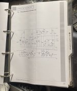
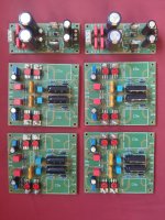
I thought I would share my solution for easily prototyping passive crossover filters.

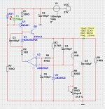
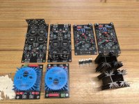
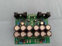
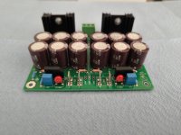
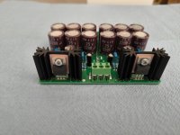
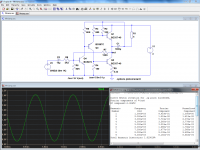
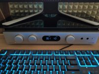
I designed and made a few modular boards that can easily be connected to each other. They make it easy to try out different topologies and to compare different component values. Here is an example of a basic 2nd order 3khz crossover with a 6db lpad on the tweeter.

board-14.jpg


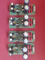
Since my speakers (live edge open baffles) emphasize the beauty of natural wood, I decided to make these from solid walnut with a natural hemp oil finish. Completely unnecessary, I know, but hey, it makes me happy ;-) These boards weren’t the cheapeast or easiest to make, but I had fun making them.
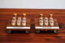
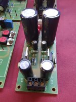
Busbar

board-2.jpg
board-5.jpg

board-4.jpg

The busbar units feature two (2) push terminals and six (6) mini banana plug terminals, all wired to each other.

Typically I use one busbar module connected to the amp’s positive (+) terminal and one connected to the amp’s negative (-) terminal. If building a parallel crossover, I can branch out to each driver’s individual circuit.

Busbar JR

board-6.jpg
board-7.jpg

The busbar JR features one (1) push terminal and four (4) mini banana plug terminals, all wired to eachother.

These are useful in series crossovers and the occasional busy junction.

SP

board-8.jpg
board-9.jpg


The “SP” unit stands for “series parallel”. This module puts one component in series with the output and one component in parallel with the output. It can be used for many things, such as creating an LPAD, an RL high-pass filter or a 2nd order filter.

The inputs and outputs include two (2) positive input terminals (+), one positive output terminal (OUT +) and two (2) negative terminals. By doubling up the positive and negative terminals, these modules can easily be daisy-chained.

The series component is connected with two push terminals. This makes it very easy to swap components to try different component values. The series connection can be shorted with a short length of speaker wire to use the SP module as a single parallel component.

The parallel component is also connected with two push terminals. The parallel component can be omitted to use the SP module as single series component.

There is additionally a “bypass” DPDT switch that shorts the series component and opens the parallel path. With the bypass engaged, it is as if the components have been removed from the circuit.

SPSP

board-11.jpg
board-10.jpg


The “SPSP” unit stands for “series parallel series parallel”. This module acts like two SP units sequenced together, “A” and “B”. It can be used for many things, such as:
  • A fourth-order high-pass or low-pass filter.
  • A second-order high-pass AND a second-order low-pass filter.
  • A second-order filter AND an LPAD.
  • My personal favorite: an RL high-pass filter AND an LPAD.

The inputs and outputs include three (3) positive input terminals (+), two positive output terminal (OUT +) and two (2) negative terminals.

There are two DPDT switches. The first bypasses the first SP components (“A”), and the second bypasses the second SP components (“B”).

The switches open up lots of possibilities, such as:
  • Compare different LPADs on “A” and “B”.
  • Compare different second-order filters on “A” and “B”

Connections

I use small lengths of speakers wire with solder-on banana plugs to easily wire these modules together and to the speaker drivers.

Thanks for letting me share!

Attachments

  • board-1.jpg
    board-1.jpg
    417.7 KB · Views: 71
  • Like
Reactions: wchang

Contemplating Quitting DIY

In an effort of simplifying my life I’m considering quitting the DIY route. It takes me a long time to get stuff built (two years in on EL34 Baby Huey’s and don’t even have all the parts yet) and I’m thinking it might just be easier to buy good quality gear and be done with it. I’ve built tube amps, guitar amps, speakers, etc. what’s happening also is I’m ending up with stuff I have no room for too. I enjoy the process, but I’m in my mid 50’s and would rather spend the time listening instead of building, tweaking, etc.

Anyone else been in this predicament?

Help with Capacitor Value for XO

Hi everyone,

I have been having issues with an Infinity Intermezzo 3.5c Centre Speaker. The mid is very very low, almost no sound.
I have traced it back to one of the capacitors.

The service manual shows C6 as 2.5uF 100V, however on the board itself it says 25uF 100V.
Since it's by a factor of 10, I'm hoping someone can look at the XO and can confirm if it should be 2.5uF or 25uF.

The original cap is blown and the jacket on the outside is damaged so I can't read what the actual value is on the old cap.

Any help would be appreciated.

TIA

Attachments

Projects by fanatics, for fanatics
Get answers and advice for everyone wanting to learn the art of audio.
Join the Community
507,534
Members
7,875,945
Messages

Filter

Forum Statistics

Threads
405,672
Messages
7,875,945
Members
507,534
Latest member
Fireball2020