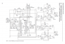
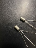
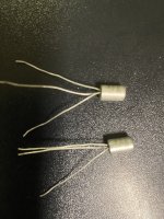
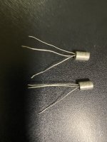
I am in the process of restoring my Sansui 9090 driver board (F-2436 late production). This may be a dumb question but here it is. TR07 and TR08 are I believe bias transistors. They are both 2SC984 s but one has a ‘B’ inside a circle and the other has a ‘C’. I have the ones with ‘C’. My question is do I need a ‘B’ for TR08? I seem to remember reading that the C means the collector is attached to the can and I suppose B would be attached on the ‘B’ can and if they aren’t correct can wreak havoc on the circuit. Is this true? TIA
Do you think TDA1540 is old ? Do you think PCM53 is very old?Today I am making an older version of MP1936, enough to make MP1936 reappear in the world.which works in pure NOS mode. Reproduce a warmer sound than the TDA1540.The production is divided into four parts. The first audio source part uses Bluetooth, USB, CS8412-coaxial input, the second format conversion, uses pure NOS working mode, does not use any filter chips, and the third uses oversized DAC audio MP1936. The fourth part is the power supply part.
Thought I'd share this project I've been working on.
Background: As part of my PA system, I've been running some 15" ported subwoofers for a while. Beyma 15P1200Nd, compact boxes tuned to 40Hz. They've generally been good to me, but there are some problems in the construction (drivers hitting the grilles, stuff like that - mostly my own fault) that meant I was never 100% happy with them.
Drivers have moved on since those Beymas - more Xmax, more power handling. As an example, I happened to have accumulated 3x Faital 18XL1800 drivers, which feature an Xmax of about 20mm, and long-term thermal power handling of 1600W. Short-term, they'll take in excess of 3KW.
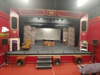
I have a good relationship with a local theatre director, and he'd hired me for a show called Into The Woods, which features (among other things) a giant. When I suggested that I build some subwoofers capable of strong very-low-frequency output for the giant's footsteps to be felt as well as heard, he was enthusiastic about the idea.
After some messing around with Hornresp, playing with cabinets of varying sizes and complexity, I decided on sealed boxes for these drivers. The reasoning is this: at 40Hz, they'll keep up with the previous ported subwoofers, which were usually loud enough. If I need these new subwoofers to go louder, I can raise the low-frequency cutoff, gain efficiency, and put out more SPL. Similarly, if there's plenty of Rig For The Gig, I can throw more power at them and get more LF extension. The cabinets would also be very compact, which is a Good Thing in the live sound world.
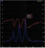
The venue in question is small (100 seats), so I decided to push for maximum LF extension:
I set off with a 12dB/octave lowpass filter at 18Hz (the red curve), which gave me a response that's pretty flat across the subwoofer range. Then, I decided to increase the fun-factor, and made it 18dB/octave (green). Afterwards, I increased the subwoofer level accordingly, so that the crossover to the main speakers (approx 70Hz) lined up well.
Power and processing was done by the rack of Powersoft T-series amps: Login to view embedded media
With the T602 bridged into two of the subwoofers, and the first two channels of the T604 bridged into the third subwoofer. Result: around 3KW per driver - enough to make use of the driver's generous Xmax for short-term peaks.
The giant's footsteps were played by timpani, as part of the show's pre-recorded music. Running that section through an RTA, the timpani had strong content down to 30Hz. While that's pretty useful (and would've been fine, I'm sure), these subwoofers can go lower, and I wanted to make use of that. Within the mixing desk, I took a digital split of the music input, applied a low-pass filter at about 80Hz, put it through an octave down, and mixed that into the subwoofer feed. The results were a lot of fun - even the lighting engineer was impressed.
This venue hadn't ever been subjected to a PA system like this, so all sorts of interesting rattles were apparent. By far the most distracting was a light fixture, so that one was removed entirely. With that gone, the quieter and more distant rattles contributed to the "there's something big coming this way" effect, so we decided to stop chasing perfection and have some food instead.
I found time to play a few bits of music (without the octave down), and the high output combined with serious LF extension was an excellent experience. Violence by Andy Stott was a good demo.
I think that about covers the story for the subwoofers.
A few other notes, if anyone's still interested:
The main PA speakers use a Faital 10HX230 per side. Ported boxes, tuned to 70Hz. I rather like those.
The subwoofers have a port at the back, where a tunnel can be placed to vent the rear of the driver's motor. I plan on doing some thermal testing to see if that's necessary, but for now the vent is blocked and heat remains in the cabinet. Not a problem for this show - the duty cycle was very low.
While the mixing desk and amp rack was placed side-of-stage, I mixed the show on a set of iPads from the control room. That kept the cable runs relatively short, and allowed me a good mixing position. During the more dramatic moments, the cupboards at the back of the control room were rattling.
In all, I've had a lot of fun here. It's good to be back.
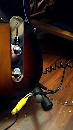
Not having parts (nor money) for a box, jacks and a rotary switch I took a cheap guitar cable and junk alligator clip to test the tonal effects of added capacitance to a pickup.
Hearing what 270pf and 560pf do with the bridge pickup on my Glarry Tele, I think I could have avoided b
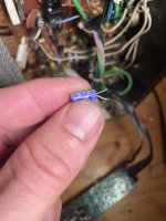
fixed left channel distortion by actually soldering wire to volume pot
adjusted DC and bias
recap (except 4 filter caps, need to source)
remaining problems:
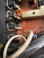
there is one capacitor that is not in the SM (see pictures - it is not in the parts list and not on the diagram). Is is named C690 and the original one is a 3.3 µF, 25V. It is just next to the "normal in" socket. What is this? and do I just replace 1:1 and forget about it?
there is a low hum in the speakers. Is does not increase with volume. It dissapears when pressing the "low level" button. It is from the pre-amp somewhere (is not there when using an external preamp). The pre-main plugs are sensitive to picking up more hum when touched. Not sure if this i normal. Internet (chatGPT) says that pre-amp hum can be due to degraded main power filter caps. Could this be it? They are old and bulging. Also when only present in pre-amp section?
the VU meters seem to react relatively little. Is this normal? I can balance them with the trim pots and they respond "normally" to music, but I need to crank volume quite a bit to get them past the first 1-2 leds
What main filter caps should I use? they are 4700 µF, 50 V. I am in Europe. I have a hard time separating one from the other.
This is my initial project. It is still working today. Accompany me every day during the pandemic. It is a work from 7 years ago. The TDA1540 with 16BIT is unbelievable to everyone now. Because his voice can rival the most popular 24 bit chips currently available. I used OPA128 operational amplifier. Make its output effect as clear as water.Now share with everyone.You will get his PCB at a very low price. But he is in China.If you are a friend of the European Union. Please provide the IOSS number, which consists of IM and 10 digits. The mailing time is about 10 days. All PCBs consist of four parts: audio input board, format conversion board, DAC decoding board, and power board. You can play app content through a Bluetooth chip (purchased in China, manufactured in Shenzhen), or use CS8412 coaxial to play CD content. COMBO384 can also be used to connect to a computer for playback, and there is also an external input IIS interface for connecting to Philips turntable playback. I will provide Taobao product connections. You can use Taobao's overseas warehouse to purchase. If you need assembly instructions and BOM list, please send an email: 410746700@qq.com,My store address: hikvocal.taobao.com
In the attached schematic: what is the purpose of the resistors and capacitors? I understand the transistor, but the other components are not referenced.
I think no one is unaware of the value of these two chips, and no one is unaware of their importance to audio. I made two versions today. Operational amplifier output and tube output. I think TUBE output is what most HIFI people want. Because the sound is very warm.Now share with everyone.You will get his PCB at a very low price. But he is in China.If you are a friend of the European Union. Please provide the IOSS number, which consists of IM and 10 digits. The mailing time is about 10 days. All PCBs consist of four parts: audio input board, format conversion board, DAC decoding board, and power board. You can play app content through a Bluetooth chip (purchased in China, manufactured in Shenzhen), or use CS8412 coaxial to play CD content. COMBO384 can also be used to connect to a computer for playback, and there is also an external input IIS interface for connecting to Philips turntable playback. I will provide Taobao product connections. You can use Taobao's overseas warehouse to purchase. If you need assembly instructions and BOM list, please send an email: 410746700@qq.com,My store address: hikvocal.taobao.com
I have almost made all the parallel port module DACs, and they are really good for application in the audio field. The warm and retro sound makes you unforgettable for a long time. They are too difficult to obtain. This is a 3-year project. I have been looking for an SP9380-18 that can work properly since three years ago. Because in the 18 bit module, only AD1139 can be compared to it. AD1139 has an unattainable price. And SP9380 is indeed very rare. But recently I found him. And make it. Now share with everyone.You will get his PCB at a very low price. But he is in China.If you are a friend of the European Union. Please provide the IOSS number, which consists of IM and 10 digits. The mailing time is about 10 days. All PCBs consist of four parts: audio input board, format conversion board, DAC decoding board, and power board. You can play app content through a Bluetooth chip (purchased in China, manufactured in Shenzhen), or use CS8412 coaxial to play CD content. COMBO384 can also be used to connect to a computer for playback, and there is also an external input IIS interface for connecting to Philips turntable playback. I will provide Taobao product connections. You can use Taobao's overseas warehouse to purchase. If you need assembly instructions and BOM list, please send an email: 410746700@qq.com,My store address: hikvocal.taobao.com
I have recently purchased a used PS Audio ultralink Dac. The unit has distortion on both channels in the high frequency. The distortion sounds as if the tweeters are torn. When I play the speakers with my regular Dac, they play just fine. Also there is a loud pop when the unit locks from the coaxial to the Optical mode which is bizarre. Please let me know which part of the Dac needs to be checked and how.
Also is it possible that there is DC at the output of the Dac which is causing the above ?
My room is odd shaped and constructed from concrete block. 1 door no window. dimensions are as follows.
6m long
3.5m wide one end
5.5m wide other end
side walls are not parallel
3.3 and 5.5 wall are parallel the door is in the 5.5 wall off centre
no wall is the same length and the ceiling height is different 2.5m
concrete floor the building was built like this to avoid a drain and get max footprint
I have heavily studded the walls and bored both sides 12mm ply inside 25mm MR mdf on the surface and ceiling used rw45 insulation through out and decoupled the studs from the ceiling and i have used about 200 tubes of acoustic sealant. this room will almost airtight
my question is do i sit on the door wall approx 1 meter off the wall or do i sit at the shorter end 2 meters off the wall.
not fully finished yet so no testing done, i just want your opinions on odd rooms
I have 4 big subs in this set up and clean low end is the goal
This is a breath of fresh air compared to the high order qw noise I’ve been messing with more recently. Nice low frequency without the extra ringing and funk up top .
traded all That for some port wind noises though….
good ole Mr McBean (horn resp)is always spot on when I ask him to simulate things 💚🙏🏻
I have a couple of old PA amps that I would like to repurpose as 50W monoblocks.
The power supply uses a 370V secondary with two AX50s as a voltage doubler, so the unloaded EL34s have 830Vdc on the plate, falling to just under 800V when at maximum power, 70W for the PP pair. The voltage doubler also provides around 420V for the screen supply, from the non-doubled rectified output.
Does anyone here think it is ok to use modern tubes this way? I am thinking to replace the doubler with a straightforward FW rectified solution, so B+ would be around 420Vdc.
Annoyingly the EL34s are fitted with just 6mm between them so alternate tube options are severely limited. I had been thinking this was a job for an EL38.
I purchase a Diamond Audio D7401 that had been "repaired" by someone before I got it, he bench tested it and it was fine before it shipped. It's taken me ages to get this thing installed so I'm not looking to lean on the PO for help..
The amp does power up and "work" but if you put any real gain to the input it starts what seems like clipping and it always sounds distorted.
So I found the attached schematic on the internet which does appear to match my amplifier. First thing I did was check rail voltages, 15V supply and "Aux supply". I have about 64VDC at the rails and the 15v supply looks ok too. The mystery to me is this Aux power situation, which is where I think the problem may be, because I have +64v roughly and -72v so there's a large imbalance. Looking at the regulator in the diagrams if my understanding is correct this should be +/- 5V??? They're calling out 7805t and 7905t regulators.
Am I correct? I may be completely misunderstanding things.
I'm a newbie who lives in California. I joined this forum last year to make ACA and it runs beautifully.
I would like to learn more from experts in this forum.
I’m a new member of DIY Audio and recently started learning a little about electronics. I have no training in this field but would love to learn, unfortunately I feel that I am too old to go to school now. I joined DIY to ask questions but probably won’t be able to answer any. I have gotten a lot of information from this site and am looking forward to learning more about electronics.
Hi everyone
I urgently need your help on a Meridian 556
It plays normal without any anomaly except that if ever I switch off the pre amplifier before switching the Meridian 556, then I get a loud buzzing (vibration) coming from the relays. Whenever I switch back the preamp, the buzzing stops and the Meridian plays ok .
What could be the cause of this problem
ThAnks
Regards
Been working through a couple of these units, and can’t seem to get it stable at high volumes.
All voltages seem good despite it being converted to solidstate rectifier (pi filter added to get voltages back to 20v high of published).
The tertiary feedback tap measures, and seems to be doing its do.
It oscillates with unit volume max, and preamp feeding it (10k outZ) through both a 15095 bridging octal module, or 15335 bridging 1:1.
I have it biased at around 60% diss.
Seems to get to a point where it just lights up.
The snubber across the power tube plates is new.
Thinking about adding a snubber across the phase inverter feeds, but dont want to shave highs. Any insight most welcome.
One Tektronix P6114B 400mHz probe, 14.1pF, 10meg probe with a new retractable tip, mini-grabber ground, and 2m cable. Listed for a TDS 380 scope, but worked great on my 2236A and 2465B.
Excellent condition, one of many probes I bought from a metrology/testing/repair lab.
I've been working through this one for a while now and I have nailed down enough of the design details to do a board layout.
Firstly a bit of background as this is not my first rodeo with the Aikido.
My first was a Tubes4hifi.com SP14 kit which I have absolutely loved the sound of since it first fired up something like a decade ago. http://www.tubes4hifi.com/SP14.htm
I've also built one using Broskie's 12vac Aikido pcb. New Aikido 12Vac PCB and part kits
I built the 18vac version using 12AU7 tubes. This is testing in my system. It's an amazingly elegant solution with a great sound but it was made for another project.
This brings us back to the SP14.
I chose to use a custom chassis instead of the stock one and this has created quite a headache. I simply cannot make the 254mm x 150mm pcb fit properly into my chassis without fouling on some other component.
It has been upgraded and rebuilt several times over the years but I've never been satisfied with the chassis layout.
Last time the SP14 ended up on my healing bench I decided I was sick of battling the blasted thing. It was time for a new solution. Time to salvage the components and find some new boards that fit.
But after much mocking up I discovered that it is just a weeny bit too large to work in my chassis. I also don't like where his ins and outs are located.
Thus I came to the point where I have to make my own boards.
Now, the design outline:
1) Mono board for maximum flexibility in chassis layout.
2) Within 100x100mm to take advantage of the JLCpcb special.
3) Separate PSU for maximum flexibility in chassis layout, also the JLCpcb thing.
4) A textbook 6SN7 aikido like the old SP14
5) At least 50mm spacing for coupling caps for flexibility. I've always wanted to try some NOS Soviet caps but they never fit.
6) 12v heater supply to take advantage of Eba with a series/parallel selector switch so that I might try 12SN7s
7) Signal I/O and PSU I/O on opposite sides of the board for chassis layout purposes.
8) Fastons for PSU connections, Screw terminals for signal connections.
So here is what I have come up with so far.
I've separated the signal ground from the onboard decoupling.
I managed to get 58mm between the widest pads on the decoupling caps.
May I please ask for some feedback?
Does it pass muster?
Does anybody see any flaws?
Any suggestions for where things could be done better?
Insults are fine as long as they are witty.
This time I will be documenting my build of the Aleph P v1.7 from Jim’s Audio in HK. Now before you start giving me grief for this (as some no doubt may be so inclined), let me lay down some groundwork.
I first learned about the Aleph P during a preamp discussion in which I was curious about a variety of technologies. Specifically, I was intrigued by the multiple “flavor” options of the Schiit Freya+. Mr. Pass suggested I look at the Aleph L which has both a passive and active component depending upon the position of the volume control knob. While researching that product, I ran across another conversation that discussed the Aleph P. Similarly intrigued, I kept reading about that one and Mr. Pass made comments that he preferred the sound of the P over the L (paraphrased). Given that I have built an Aleph J amp -- and it is a balanced device -- it seemed natural that the balanced nature of the Aleph P would be a good companion to it. So off I went on a mission to learn as much about the Aleph P as possible.
Search revealed several folks who had built and provided board sets for this design once upon a time, but at the current time there aren’t any folks in this community who do so. A web search revealed Jim’s Audio had a design as well as matched semis for it, so I placed an order.
Disclaimer: New to DIY, I was unaware of the conflict that brewed within the community for those who develop products based on Pass designs who are not members of DIYA or aim to make a profit off of his work. That's not lost on me. So call me ignorant for not making the connection. I’ve already had the IP discussion with others in the community, so no need to bring it up again. I did attempt to contact Mr. Pass through a couple of channels to discuss the status of this design, but it’s possible my message didn’t reach him. I realize he’s a busy man with hundreds of emails to go through daily, so no hurt feelings on my part. There are no other options for purchasing boards for this design, this version of the product is available, I bought it, and it’s my goal to complete it. This is the tale of that project and is meant as an educational experience. I don’t expect assistance from community members who are opposed to this particular version of the Aleph P preamp, only humbly ask that they allow others to follow along with the build. If I fail (or it fails), then that’s on me and I take responsibility for my actions.
I have searched on the model number and found one post, about a transistor type in the receiver. In my case, the receiver simply quit in the middle of a song. The remote works, the relays click, but that's about it. I'd like to attempt a repair, but I'm lost w/o some information. Does anyone have a suggestion about where to get a schematic? Or in lieu of that, an approach that that might get me started? I have moderate electronics skills.
1 pair SB Audience 15SW800, excellent condition. 565$ shipped con USA.
1 pair TAD 1601A, excellent condition. Original cones and voice coils, new surrounds and spiders 1/24. $1865. shipped con USA.
1 pair GPA 416-8B, excellent condition. $1865 shipped con USA.
I have an old home theater system, a LG HX506DI, which is breaking down for the second time. I'm thinking of giving up on it. I would just like to recover its two speakers and subwoofer to repurpose them in a DIY amplifier system.
I would like to build an amplifier with outputs for two left and right speakers and a subwoofer, and with an optical input, so that I can connect it to my TV. Is this possible?
Discovered this forum about 4 years ago. While spent great time reading through the forum, I’ve been able to find dyiaudiostore with all the great stuff. Until now, I’ve managed to build without too much issues 2xAlephJ, F5, F5T v2, Ba2018 linestage, Nutube N1, and LX mini speakers to my greatest listening pleasure. Still tinkering with components and looking for ways how to further modify the setup. Not a big knowledge of electronics, but good at problem solving and learning fast (as this forum is a great source of knowledge and people sharing it). Looking forward to push my knowledge further.
Hi there, I am a newly retired surgeon but my avocation for 50 years has been electronics. I am not an engineer. I am a former amateur radio homebrewer and licensee who now builds and maintains solid state and (preferably) tube audio equipment. I have been building kits since the 70s starting with Heathkits and now building from schematics in old books and from web sites. I built a Nutube B1 preamp and am having an interesting issue with it but I guess I am supposed to post something here first.
I've got a broken Thule IA150B that I wanted to repair. I want some help on where to start, maybe it's a broken DC-bridge? ,
Anyway, the amplifier turns on just fine and the screen lights up, relay clicks and input selector works. However, the signal is not sent to the speakers. Instead I hear a rather loud humming noise around 200-300Hz which is not affected by volume control. All fuses seem to be ok, capacitors looks good on a first look. Only visual error is that the transformer is not attached . Any ideas?
Hi everyone, does anybody have the schematics of the MF A5 integrated amplifier?
Another question - is anyone familiar, or have made, the Russ Andrews suggested upgrade for this component?
Been secretly loving your forum for the last 4 years or so, electronics engineer that works in sw, with a passion for electrons and magic smoke ( :~) ), I made some projects from the forum (openAlpha headphones, and some more little ones) and I am looking forward to handing around with you some more! 🙂
I picked up some speakers recently, an MTM layout which sound quite good, but I’m curious about the crossover design.
The tweeter is a Vifa D20TD-05-06 and there are 2x Vifa C13WG-08-08 wired in parallel for the mid woofer.
The application notes on the tweeter suggest 2nd order with cutoff at 5kHz, but the actual for these ones is first order LC at ~8kHz (0.47 Ohm 5W and 4.7uF Poly in series to the -ve terminal)
I’m wondering if maybe there should be an inductor on the mid/woofer, but the drop off is quite steep after 10kHz so maybe not?
Hello Gents,...been a while as I was moving to a new home. Recently my DAC, a SMSL sanskrit 10-th edition MK-III, has broke down. Everything works but no output at the RCA's. Installed my old MK-II and it works for now. I'm looking for a new DAC in the range of € 200,-, maybe a bit more when it's worth it.
I know it slightly off topic but is there a DAC which works particularly well with the Wolverine or does it not really matter? I;m looking at the smsl DL100 as a replacement.
Any comments tips welcome...
Anybody tried this? The attraction would be to take advantage of the Room Perfect and sub-woofer integration capabilities of the 1120. The 1120 has line level outputs as well as speaker level ones. The line level outputs max out at 4Vrms, so not enough to drive an F4 to maximum output, but maybe enough for fairly sensitive speakers. The full amp does 60 wpc into 8 ohms ie more than 20v so more than enough for full output from the F4.
As part of my PA system, I've used some sealed 18" subs for a while. I quite like them for certain things, but they take a lot of power and they don't go as loud as a cone that big would suggest.
More recently, I've been playing around in Hornresp, and realised this:
While having the option for the 18"s to hit 20Hz can be fun, it's rarely useful in a PA system.
12" PA sub drivers are sometimes made with the same motor as a 15" or 18" driver, which means they have a lot of motor force for the size of the cone, and could therefore produce decent LF output in a small box
The problem with small boxes is that it's difficult to fit a bass-reflex port in there, especially if we're chasing output density.
Passive radiators can help in low/medium-power applications, but when a subwoofer is expected to receive ~kilowatt power levels for hours at a time, heatsinking becomes an issue.
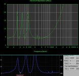
For a start, I modelled a Faital Pro 12RS1066 in a 28L PR enclosure using Hornresp. It looks like it's possible to use 2x PRs tuned to 40Hz (300g added per PR) and a 4th order HPF at 35Hz just about keeps PR and main driver excursion in check. Result: >120dB output at/above 40Hz while (just about) keeping within rated Xmax.
I chose the 12RS1066 because I have a couple of them sitting around here not-doing-anything, and thought it might be fun to put them to work. Link: https://faitalpro.com/en/products/LF_Loudspeakers/product_details/index.php?id=201050125
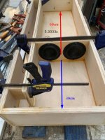
I plan on using a small front baffle to hold the Faital driver, and then mount the PRs on opposite sides of the enclosure for force cancellation. Obviously the PRs and driver will take up some cabinet volume, but I'm still expecting an incredibly compact subwoofer.
I'm attaching the Hornresp file, for if anyone wants to play around.
Before I drop the cash on a pair of PRs to test, can anyone see any problems with this?
You have to excuse me if this has been discussed before.
I bought a Protodac diy kit and just want to build a super simple dac. I was thinking of connecting it to a Amanero usb module.
But since I am a high power electric engineer and most used to speaker building and ready simple diy kits there is a few things I don't quite have the hang on.
First thing I am wondering about is how to power the usb module. There seems to be a +3,3v supply pin, but when I read the leaflet I get confused when it says it is powered by 5V USB bus.
So is the usb module powered by the source through the usb cable?
I have been a diy speaker builder for the last 10 years and have built a number of successful projects over the journey.
Recently I started to get into horns. I built my dad a ecconowave type speaker a few years back and more and more as time has gone on I seem to love how they sound. I have a very large shed/man cave and so horns make a lot of sense for my next speakers.
This project started as I had a bunch of material left over from various woodworking and renovation works.
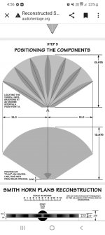
Basically a year or so ago I built some smith horns with left over 26mm laminated beech that I had from making bathroom vanities. Taken from plans on another forum and Adjusted to 5 cell and 90* horizontal pattern. I'm aware that diffraction horns have a mixed reception but they look cool af so that's where I started.
I have recently picked up some new in box faital pro 3fe22 8ohm drivers of Facebook marketplace for a very good price decided to give it a go in the smiths as I have some time at the moment to play with things- self employed, wife and 2 young kids......
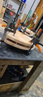
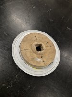
Started with a very rudimentary 2 litre airtight bucket filled with polystuff as the back chamber (obviously this is too big but just playing as a test of concept). Made a 15mm ply and 3mm mdf ring with a 25mm square hole for the entry to the horn- see attached (this is before file work to make it all neat and even so it looks pretty basic in the pic).
After a previous modification, this very stable ultrasonic rotary vinyl record cleaning machine is now completed.
I used a geared motor as its rotational power.
Ultrasonic cleaning can deep clean the record very clean, but it will not damage the vinyl record.
The machine can be set to a timer and can clean a set of records in about 20 minutes.
Looking to make a center speaker to try out with movies. I have a few drivers available, some I'd rather use more than others. I'd love to utilize the tectonic tebm46 that I've had for years. I feel it's wide dispersion will be of value here.
I would like to use a wmtw configuration and was wondering what sensitivity would be ok for the woofers to work with the tebm46. My math is probably off but if I recall you gain about 3db from adding a second woofer? The tebm46 is 86db. Assuming baffle step loss of 6db, I should be safe with woofers around 88db and under. Please correct me if I'm wrong.
Hi, the other day sorting stuff on my old bookshelf I found my old Tietze&Schenk book, and it suddenly came to me that I want to rekindle my DIY life from like 40 years before...
I wanted to start small, so I started to look at headphone amplifiers, and after a couple days of research I was hooked... I found myself fascinated by the most simple circuits with one or two active components, in their wide varieties, and I want to build them all, and hear, compare their sounds with my own ears...
I have a gazillion questions, and I registered here to have an option to ask experts if (when) I cannot find answers through my own research.
Thank you!
I've been wanting a pair for a long time and have been looking at review's, one review, said, as they are not ported, where has the bass gone, etc. Has any body ported a pair of these as they are not cheap if any thing went wrong, if a hole was cut out with a hole saw, It could be glued back if it didn't work, but has anybody tried this. Paul
I think some friends have seen the previous post because he was very confused. I think I will reorganize and send it to him. This is a very old DAC, with a price of $200 per unit back then. Because it is the first generation chip for recording magnetic tapes. So he is very valuable. He works great and can recall warm vintage sounds. You can purchase PCB boards and ship them from China. If you are a friend of the European Union. Please provide the IOSS number, which consists of IM and 10 digits. The mailing time is about 10 days. All PCBs consist of four parts: audio input board, format conversion board, DAC decoding board, and power board. You can play app content through a Bluetooth chip (purchased in China, manufactured in Shenzhen), or use CS8412 coaxial to play CD content. COMBO384 can also be used to connect to a computer for playback, and there is also an external input IIS interface for connecting to Philips turntable playback. I will provide Taobao product connections. You can use Taobao's overseas warehouse to purchase. If you need assembly instructions and BOM list, please send an email application: 410746700@qq.com
I am a retired old man,was worked in electronic and ic assembly company.
Audio amplifier diy is my hobby,l often assembly audio kits for tasting different characteristics.
Amp is a complicated unit with no standard rules fit all problems,especially when assembling and wiring.l always search website for problem solving when encounted.
I join diyaudio is expect to get people's guidance and exerience to possibly improve problem and enjoy music.
I am very honored to have purchased 2 DAC726 chips, which are identical to DAC1136 and DAC73. These are chips from a long time ago. A chip used to record cassette tapes for opening machines. Today I designed a DAC audio decoder that works with this chip. He works great and can recall warm vintage sounds. You can purchase PCB boards and ship them from China. If you are a friend of the European Union. Please provide the IOSS number, which consists of IM and 10 digits. The mailing time is about 10 days. All PCBs consist of four parts: audio input board, format conversion board, DAC decoding board, and power board. You can play app content through a Bluetooth chip (purchased in China, manufactured in Shenzhen), or use CS8412 coaxial to play CD content. COMBO384 can also be used to connect to a computer for playback, and there is also an external input IIS interface for connecting to Philips turntable playback. I will provide Taobao product connections. You can use Taobao's overseas warehouse to purchase. If you need assembly instructions and BOM list, please send an email application: 410746700@qq.com
Hello, greetings to all DIYAUDIO members. I am here asking for some help regarding my amplifier.
I will tell a brief story about what happened.
That day I was busking using the FISHMAN LOUDBOX ARTIST and I noticed that my amp was not working as usual. then I tried to open the body amp and I didn't see anything happening.
so I went to send technician "A" to repair the amp. the technician said "the preamp IC was found to be defective" so I bought it and the model was TAS5603B and the technician installed it. And after a few days, the technician changed the item but my amplifier is still not working. I took it back and changed to another technician.
then I sent it to the other technician "B" and when he opened the preamp IC and found that the board was burnt.
The technician asked me to look for the fishman loudspeaker schematic but couldn't find it. until I found this forum to ask for help from all my friends to get the schematic.
does anyone also had this problem.
I am trying to get the UCA202 to show up as input but it will only show my laptops mic and headphone input, no matter what i try.
It is driving me nuts.
I have two H/K home theater amplifiers. I bought the AVR 151 as faulty, the owner said it wouldn't turn on and the power LED was blinking. When it arrived with shipping though, it was already working perfectly fine. Probably this good operation is only temporary, it will not last long, because when switched on there is a not very loud but audible hissing sound from the switching power supply section for a few seconds, which then stops, and currently all functions of the amplifier work fine.
Is there anyone here who is familiar with SMPSs and could tell me what this buzzing sound could be? Because it doesn't seem normal and could indicate some kind of fault that will come out sooner or later in the unit.
And a friend of mine gave me an AVR 171 which behaves the very same way, the buzzing sound comes for a few seconds, goes away, but all the functions of the amp are currently working fine.
So it occurred to me that it's not a fault, but it could be that the power supplies in both amps are dying.
The SMPSs of the AVR 151 and AVR 171 is the same, except that some electrolytic capacitors in the 171 are bigger.
I have two H/K home theater amplifiers. I bought the AVR 151 as faulty, the owner said it wouldn't turn on and the power LED was blinking. When it arrived with shipping though, it was already working perfectly fine. Probably this good operation is only temporary, it will not last long, because when switched on there is a not very loud but audible buzzing sound from the switching power supply section for a few seconds, which then stops, and currently all functions of the amplifier work fine.
Is there anyone here who is familiar with SMPSs and could tell me what this buzzing sound could be? Because it doesn't seem normal and could indicate some kind of fault that will come out sooner or later in the unit.
And a friend of mine gave me an AVR 171 which behaves the very same way, the buzzing sound comes for a few seconds, goes away, but all the functions of the amp are currently working fine.
So it occurred to me that it's not a fault, but it could be that the power supplies in both amps are dying.
the one I have access to is off by .7ohm I need to replace a 3ohm one but I cannot find anything close. if I parallel resistors to get the right wattage, the closest I can get is 3.7ohm (measured using meter)
Winter's coming, and so are the Class A amp builds.
This time I'm looking for someone from the EU who's got a surplus pair of F4 PCBs from the diyAudio store. I know that I could order from the store, but I'll ask here first.
I could also trade for a pair of Peter Daniel's F4 PCBs that I have. It's just that the diyAudio store PCBs would be a better fit for my heatsinks.
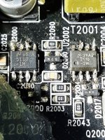
I have an amp already repaired, but there are two difference reference (U2000 = LM5110-1M and U2002 = LM5110-2M).
What is the correct reference ?
Thanks
Hello.
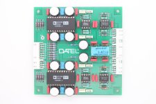
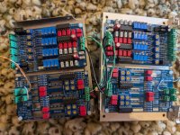
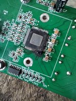
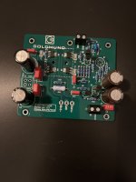
I have bought this boards supposed to be from true Goldmund amp Telos 600 but I’m pretty sure they are not Goldmund boards because they doesn’t match to telos 600 schematics.
Maybe this is a protect already discussed in this forum. I need the schematics to install the fets and some transistors that are not populated. My big concern is the N jfet that it is not 2N5565 but U402 and I don’t know if this is just something to install it or the input board is designed for U402 Jfet.
Im using my Parasound Zamp v.3 for my computer audio system. The chain goes to the computer, USB isolator, USB DAC, ZAMP, and Monitor Audio Silver 2 bookshelf speakers. The amp has always had a hum/hiss with no inputs, but it went away with the DAC so I never though much about it. I recently upgraded my DAC, and the new DAC goes idle after a few seconds, essentially shutting off the output, resulting in the ZAMP humming/hissing. I swapped amps with a Yamaha M-45 and the old Yamaha is silent with in the exact same setup. You can even unplug the RCAs from the back and the Yamaha stays silent.
I'm thought it might be floating inputs that the Zamp doesn't like. I checked the resistance between ground and signal, found it to be 19.5kohm (the Yamaha measured 20.4kohm) so that doesn't seem to be an issue. The ground checks out (and the Yamaha doesn't have issues), so I don't believe it is a ground loop issue (I even ran a separate ground to the chassis of the amp and tried a cheater plug). The Zamp also has the option to lift the ground, and that has no effect. I opened it up Zamp and didn't see any obvious issues with the caps.
The Yamaha is a tank, and I don't have room at my desk for it. How do I get the Zamp to be quiet? I tried an app called Sound Keeper, which keeps the DAC from sleeping, it works but that seems like a Band-Aid solution and doesn't fix the real issue. Is this just normal for a Zamp? Does it need a recap job (or just bad design)? Is it time to upgrade to one of the new TPA3255 chip amps?
I recently heard the Linkwitz LX521 and was quite impressed to say the least. As a DIY project this would be a bit too much, though, and a bit too pricey - but which got me thinking.
Linkwitz also designed the Orion, and I was wondering, if someone has done a project/plan/kit to build just the midrange/tweeter part of the Orion leaving out the woofer part, and just filling in the lower end with e.g. a Rythmik sub?
I've been an LS3/5a user since my first job, which was at BBC Research Dept in Kingswood Warren, although I was in the service planning dept. But I was able to use my staff discount to be buy my first pair.
Used them ever since, although I added the AB-1 when it came out, then later the AB-2 from Stirling, along with upgrading to Stirling thin-wall cabinets and Cicable external crossovers and then Stirling V2s with Xtracable external crossovers. Always with Quad power amps (306->707->909 monos->QMPs), and lately Music First Audio pre-amps.
So earlier in the year I visited Stirling Broadcast to get some help replacing a blown T27, but saw that Doug was suffering health issues and also saw that he had accumulated a lot of stock that he had built up in the covid era. His friend and neighbour, who was helping look after him, pointed this out and also questioned what could be done with it. As I like a challenge I said I would help and try to get it all sold. That was back in May 2024 and I am still working on it!
So the reason for joining was that I have always wanted a better quality crossover in the AB-2s, feeling uneasy that the crossover in the V3 LS3/5as is of a very hgh quallity (nearly as good as my external crossovers) but when using the AB-2 as it was designed, this crossover is being fed a band-passed signal from the mediocre crossover in the AB-2. When using my external crossovers the situation isn't quite as bad as the HF of the LS3/5a comes straight from the external crossover and doesn't touch the AB-2.
Now I am a software engineer that is trying to retire early so loudspeaker design is not my forte. When I worked at the BBC I did start to get into it and built a box to test the resonant frequency of a Nakamichi speaker I was putting in my car so I could build an enclosure for it, but never got around to completing that project.
Although I have tried to persuade Derek Hughes to design me a better AB-2 crossover (and AB-1 before that) he doesn't seem very enthusiastic (perhaps unsurprisingly), but he has pointed me to a suitable air-cored inductor to use, and also made some comments about replacing the two capacitors (one elctrolytic and a smaller PP which must be a bypass -according to what I read only a few days ago!).
I've been reading a bit online and also just bought some courses on udemy (!) but one of his specifications, that the replacement PP capacitor (the electrolytic is going) has to have a voltage rating of between 50V and 150V is causing me problems. So my first technical question after this introduction is probably going to be about that !!
Getting started on a midbass horn for use with my A290s. I have some thoughts on the midbass enclosure design I'd like to clear up with some of you horn experts. Hornresp would probably answer this for me, but at the moment, the software wont open properly for me without errors.
While calculating the WG profile, I was curious (hoping) if the throat surface area appropriate for a single LF driver could be simply assumed to double when adding a second identical driver? Does this also potentially shorten the total WG length?
In my case, 2 x B&C 12MH32s per side were planned for use in a FLH design similar to Inlow spec FL midbass horn. I was initially going to use a single 12PE32 per side, but started thinking about trying the altec A7 expo-reflex design instead. This brings me to the next potential issue, given the lack of rear chamber on the A7 screwing up the WGs performance. In the past, I've only built FLHs with reactance annuling rear chambers, not with the reflex rear enclosure setup of the A7. I'd imagine the transient response of a well designed traditional FLH would go south with the expo-reflex design, as most RLHs with 1/4 wave TLs would have similar issues not having any reactance annuling.
The 12MH32 requires a smaller throat entry surface area than the 12PE32, so my theory of doubling the total throat entry surface of a dual LF driver horn would allow for a shorter horn length, assuming this would be like starting the WG profile at a larger throat surface area entry point and ending at the same 1/2 - 1/4 pi mouth area? Is my theory correct on this, or am I just being misled by my morning dose of meds?
Three excellent condition Sencore 39G292 150mHz low capacitance probes (photo shows 2). Note: some sources cite this as 100mHz, others state 150mHz. These are the mates to the SC3100 Sencore 'scopes, so they have both a ground clip lead and the DMM lead for that 'scope model. Two of these have the DMM lead, the third does not, so it is discounted (buy all three for the best price).
I've tested these with my Tektronix 2236A, 2465B, and Rigol DS2072A and they work great. They are a bit bulkier than Tek probes, but if you have an SC3100 and want the correct probes, or want a good set of 150(100)mHz probes for a good price, check these out.
Hi,
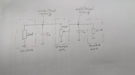
In order to match impedances of tube source, attenuator and tube power amplifier to 1:10 rule I just need explenation how source "sees" input impedance. Which of this two calculations are correct:
1. Z_pot = 10 x Z_out and Z_in=10 x Z_pot (difficult to achieve)
or
2. Z_pot || Z_in = 10 x Z_out (possible to achieve)
In attached diagram C1 and C2 represents capacity of interconnect cables. C1 is very short cable, C2 is around 30cm. I don't know if they can be ignored in this calculation.
Z_out = 4K5
Z_in= from 86K (20khz) to 330K (<5khz)
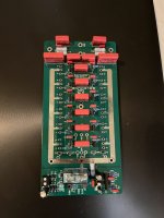
I’m working on a clone BASSFACE class D amplifier that was brought in with a burnt-out power supply and a dead output section.
It’s using 10 IRF260Ns for its output.
After fixing the power supply, I noticed the drive waveform on the output had a step on the turn-on, and the low-side FETs were running hot without a load at idle.
I changed the driver transistors from 2316, 916 to 2073, 940 respectively, and doing so solved the problem with the drive waveform. However, the amplifier was getting distortion well before the clipping point. The driver transistors on the low side, especially the 2073, were also running hot when I did this. I switched back to the original drivers to see if the distortion was also present with them fitted, and indeed it was, and it was much worse.
I also tried leaving the 2073, 940 on the high side and the original transistors on the low side, which was somewhat better. I also tried other transistors like 649, 669, and the results were much worse.
Any idea on what is causing this and how I can fix it?
Any help would be greatly appreciated. (I’m kind of new to fixing class D amps 😅)
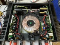
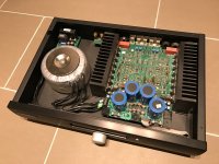
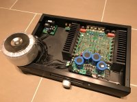
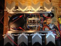
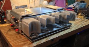
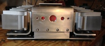
I am moving out of the country in 90 days so it is time to sell the last of the stuff I have been using. My Nelson Pass F6 (see pictures) has been above my soldering bench driving some very old Bang & Olufsen Red Line 60's. It's been good! All things must pass. First the cream, this F6 was not my first rodeo and I really like the construction for the chassis. I never intended to sell it so it may encounter some "settling" in shipment. THUS I offer it up as a complete set of (working) parts.
I have been though shipping hazards before, sometimes everything goes just fine, most times things go just fine. I have no time to make things right IF they go wrong, like one channel out upon arrival. Everything is great but you must consider it as PARTS.
Everything should hold together. It is serious construction! You can see I was free with the fasteners. I am also very good at packing! I am still no match for a 4 foot fall from the conveyer.
AS an offering of parts I figure it should sell quickly at $200.00 even if it takes $100 to ship it. I live way up the Michigan peninsula in Traverse City (49685) if you want to come and get it. That would be sweet.
I also have a sweet little BA front end as preamp I'll put in a second ad to keep things straight 🙂... and Wayne's 2018 preamp, Those same B&O speakers, and cables and...
I'm working on a sound installation that will use eight of those speakers that will be placed on a floor in a art gallery.
The speakers should be as low as possible. How can I planning the wooden box? is there any rules for that?
I'm using this 4mm plywood for laser cutter for building the boxes.
I care about the esthetic of the speakers (meaning speakers must be low as possible to the floor) but the sound quality is also consideration.
Hi, I'm not an electronics engineer, but I have a friend who is. As an amateur musician, I'm sometimes confronted with equipment breakdowns, and if I can repair them myself (for faults that are easy to detect) I do, otherwise I ask someone more competent. This is what led me to your forum to help my electronics engineer friend (who doesn't have much time) find the fault with an old Philips amp that I hope we'll soon wake up. 🙂
I meant to post this information 10 years ago…better late than never, I guess.
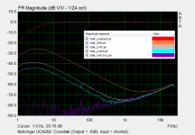
The UCA202 is not state of the art by any means, but small, light, rugged, no fiddly knobs to adjust or get noisy, and cheap…works great for non-critical travel measurement system. However, as many have noticed, if you try to use it for impedance measurements using the built in headphone amp and a 47 – 100 ohm reference resistance you will notice an issue with rising impedance error at low frequencies. I traced the problem to an unregulated voltage reference that is shared by all op amps. The op amps are powered directly from the USB +5V rather than a split +/- Supply. The voltage reference is needed to position the audio signal between ground and +5V.
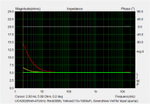
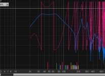
Attachment #1: A trend plot of measured impedance for a 5 ohm resistor for a range of reference resistor values used with a power amp to illustrate the issue.
Attachment #2: Here is an overlay plot showing the cross-talk vs the loop-back measurement.
- red curve is the loop back measurement
- orange curve is stock unit with inputs shorted
- grey and blued curves are with inputs shorted but bigger filter cap for reference voltage
- purple curve is when input op amp reference is switched to using the regulated Vref in the PCM2902
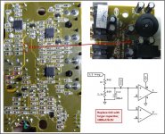
Attachment #3: One option for improvement is to increase the size of the capacitor (C13) used to filter/stabilize the reference voltage . The board has room for a 1000uF. This is a simple option that provides about 20dB improvement.
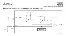
Attachment #4: A better option, if your soldering skills are up for it, is to use a separate reference voltage source for the input op amp. Rather than adding circuitry, I found from the TI datasheet that pin 14 on the PCM2902 provides a regulated reference voltage for the internal DAC/ADC buffers. Furthermore, the TI demo board schematic shows this voltage being used as reference voltage for external op amp buffers as well.
- remove R14 & R21 (required because of direct coupling in the monitor signal path, the monitor switch will no longer work)
- cut trace between pin 5 of IC5 and the thru hole (this is the shared voltage reference trace)
- add connection from pin 5 of IC5 to pin 14 of PCM2902 (conveniently available at C1)
Attachment #5: A comparison of improvements from the two different fix options with 47 ohm reference resistor.
Attachments #6,7: Excerpts from TI documentation
* * * UPDATE * * * 2024-09-23
diyAudio member kinap35 posted links to videos showing alternative fix using an LM385-2.5 voltage reference.
This method retains the functionality of the monitor switch, if that is important.
Videos links: Post #23
Cross-talk Results: Post #26
I have a single JBL 4367 plastic horn that is 22-1/16” wide and about 10” deep. Since I have no idea how to replicate it I imagine I can 3D scan it and use the file to print a copy or a pair.
Can anyone help with advice? Can it be done with an iPhone or I need a special high resolution scanner? Thanks in advance!
Good day All,
I have recently been wondering whether there is any reason to not install resistors vertically. It would save space and so the pcb can be smaller, saving cost.
Would love to get your opinions on this.