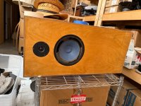
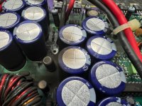
These days I found a seemingly flawless Phillips subwoofer (from a HTD5000 home theater) on the street, in a spot meant for trash, its only issue was that someone ripped off its wires.
I took it home and soldered new wires, it works, but sounded lame, despite the fact it looks perfectly intact.
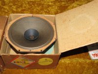
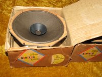
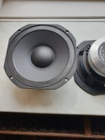
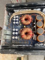
It's speaker is an 8 inch Eastech sub, FSB52A680-8300, a driver that exists for sale only here in Brazil (used ones only) and that doesn't exist even on Eastech's site itself, nor any other database.
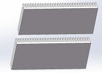
This is it:
It's visually similar to this other 8 inch sub from Eastech, same design, basket shape etc, except for the magnet, mine looks like is has only 60% of the diameter of this one here:
https://www.eastech.com/standard/asdsd4026-0301. Plus, according to the site, its surround is supposed to be rubber, mine is foam (a good quality one, but foam).
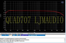
Even its Fs and Re are similar.
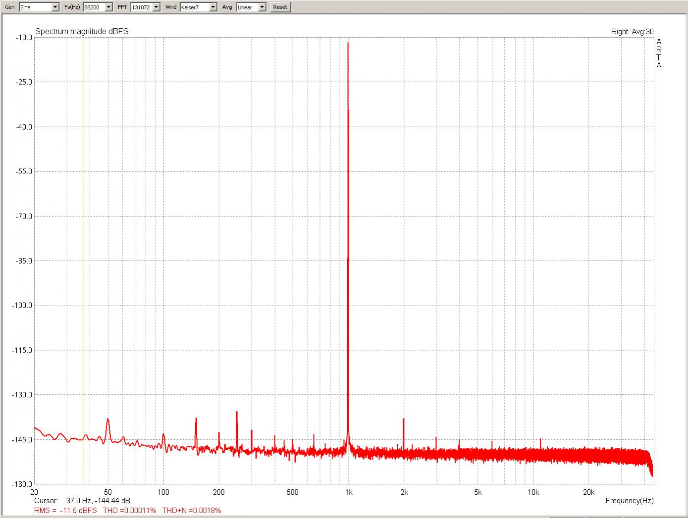
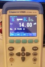
The only problem is that, after I measured its TS parameters using a setup I already used before, I've found its BL to be only 4.67 N/A, causing it to have a large Qts of 0.896.
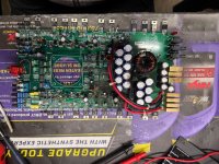
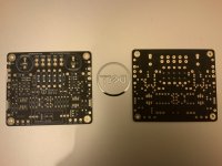
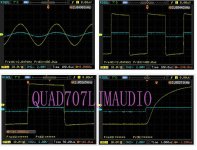
I've used this setup several times, and it never seemed to give nonsense results, I rechecked my calculations and everything thrice, everything seemed correct, but decided to do a second test:
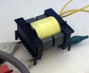
I've put a thin copper wire attached on the frame of the speaker, coming up above the cone and making a hook shape above the surround, in such a way its tip lightly touched the cone, when it's at rest, to mark its resting position (when lying on a surface, with its cone pointed up).
Then I fed it a DC current and checked how much weight I needed to pile over it (only non-magnetic materials, of course) until it returned to its resting position. When that happens, the coil force and the weight force are canceling each other out, and the surround and spider are keeping it at the resting position again.
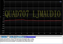
My measurement came to the result of 4.79 N/A, strikingly close to one calculated based on its max impedance, Re and side frequencies.
So I've accepted that, whatever the reason, it has a very low BL.
My question is: why? How?
Honestly I don't think this could be the result of aging or demagnetization.
Perhaps, has it always been like that?
The smaller magnet would make sense with this idea. Eastech itself has a few subs with similar Qts, but much higher Fs. None has an Fs similar to 40 Hz and such a high Qts.
But that would mean this sub was never properly tuned.
With the TS parameters I'm seeing now it's completely improper for any vented design, leave alone its original enclosure, which is why it was sounding horrible.
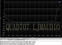
The TS parameters I got were:
Vas=35.896129906 L
Cms=0.547857247922 mm/N
Mms=33.7729816147 g
Qes=1.04372168889
Qms=6.35603786481
Qts=0.896506775221
Re=2.9 Ohm
Fs=37 Hz