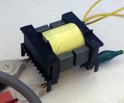
I have built the prototype transformer for a 1.2 kW LLC converter. I use an ETD49 core of 3C94 material. The primary is 35 turns. The secondary is 70 turns. My input voltage is 400V from PFC stage. The output is 400V.
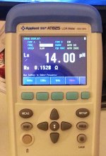
My math shows I need about 11.5 uH of leakage inductance and 50 uH of magnetizing inductance. I have attained the required leakage inductance by using overlapping and offset windings. Currently I have 14uH of leakage inductance in my design. My transformer is margin wound with about a 5mm margin.
In my transformer, it takes a large gap in the core to attain the required magnetizing inductance. The gap is on the order of 0.25 inches to get 50 uH of magnetizing inductance. The leakage inductance is not affected much by varying the core gap.
My question is this: Is using such a large gap likely to cause a problem? Is it common to use a large gap in these designs?
What effect does changing the value of Ln (the ratio of magnetizing inductance to leakage inductance) have? My current design value of Ln is 5. Is this a decent place to start? For smaller values of Ln, I will require a larger and larger core gap.
Attachments
Last edited:
A few things come into mind:
You will have a strong fringing field around the gaps, and any wiring in the area of highest flux will have high internal eddy currents causing losses and local heating, even damaging insulation and in worst cases (extreme) melting the wire.
How bad I can not say, you probably needs to test or do a thorough FEM analysis with special software.
If you have a split secondary winding you can expect the leakage inducatance to be different for the two secondary windings due to assymetri.
Second, the gap with spacers means that the stray flux from the outer legs will spread to the end of universe (eventually) , the wider gap the worse spread.
This can be reduced by using a thin (< 0,5 skindepth) copper strip shorted into one turn wound around the core outside, covering the gap. But be careful, use tape or something similar to create a air gap close to the gap between the core legs. But the strip should connect flush to the core on the outside. How wide?
Cant tell, experiement...
This is my theoretical understanding of the problem. I have no practical experience, but are very interested in any answers or comments to above from more experienced forum members.
I still hope this is helpful
regards,
Rickard
Hi cjk2, I made a smaller trafo, used a EDT 39 core with AL 2600. I used a cable tie to form a two chamber bobbin.
The windings are seperated 4..5mm. The gap I made with 0,2mm foil. 15 winding pri and 2*5 bifilar for sec. gives 160µH inductance and 40µH stray inductance.
To measure the stray inductance I shortened all sec. windings. To measure the main inductance I leave them open, measure allways at the primary.
I tried a split bobbin design but the problem I has was the leakage inductance was too large. The smallest I could get was about 50 uH. The leakage inductance was also strongly influenced by the core gap since this gap affects the coupling between primary and secondary a lot in a split bobbin design. The best Ln I was able to get by adjusting the core gap was about 2.5. This corresponded to Lr = 100 uH and Lm = 250 uH. Both of these values were too big anyways as I need between 10 uH and 17 uH of leakage inductance.
It is useful to note what the symbols I have used mean:
Lr = leakage inductance. This is measured with the secondary shorted.
Lm = magnetizing inductance. This is measured with the secondary open.
For my current prototype I went with a non-split design with the secondary on top of the primary to reduce the leakage inductance. Right now the value of that leakage inductance is about 14 uH which is in the reasonable range for my design.
The concern I have is that the gap required in the core will be too large and will cause excessive losses in the windings. I have seen copper used around the transformer on some power supplies. This may be something to investigate if the radiated field that comes off the transformer is too strong.
Does anyone know what the effect of changing Ln (the ratio of Lr to Lm) is?
I have the gut feeling that the 14µ to 50µ ratio is impossible to reach with the core/winding configuration shown.My math shows I need about 11.5 uH of leakage inductance and 50 uH of magnetizing inductance. I have attained the required leakage inductance by using overlapping and offset windings. Currently I have 14uH of leakage inductance in my design. My transformer is margin wound with about a 5mm margin.
In addition, the leakage inductance does not vary very much with the gap size (or anything related with the core): the coupling coefficient does vary, but that is mainly because the magnetizing inductance vary, and thus the Lf/Lm ratio.
I think you should double check your values, with another measurement method.
Large airgaps do cause problems, particularly with solid wire.
Ideally, the gap should be situated under the winding, ie in the center leg only. External gaps create huge stray fields making the inductance poorly defined.

I have the gut feeling that the 14µ to 50µ ratio is impossible to reach with the core/winding configuration shown.
I agree, the air gap gets too large.
With a split bobbin it was impossible to reach a ratio of greater than 3. On this transformer, it seems to be hard to reach a ratio of less than 5.
I did some more calculations and I think I have arrived at a better set of values.
If i set Fsw = 100 kHz, Qe = 0.40, Ln = 5 I get the following:
Cr = 132nF
Lr = 20uH
Lm = 100uH
I suspect the air gap required for this is about 4mm.
If Fsw = 100 KHz, then the minimum frequency of my design will be about 65 kHz. With 35 primary turns this gives a flux density of 0.14 Tesla max. This seems very reasonable to me.
I do not have another LCR meter to compare my measurements with but I will check my meter against some known inductances and perhaps measure the leakage and magnetizing inductance of my transformer using a function generator and a scope.
Using a separate resonating inductor is a good idea, as then you can ditch the need for using litz wire in the main transformer. You will still need to gap the main transformer to establish the proper value of magnetizing inductance, as the separate choke will only provide the leakage/resonating inductance for the design. I would suggest using a relatively coarse litz wire (36-38 AWG strands) to wind the separate resonating inductor to help reduce losses. I would suggest using a voltage doubler configuration to generate your output, as you then have only a single output winding to deal with and no need to worry about phase-to-phase balance like you would with a FWCT output configuration.
BTW, what is your contemplated operating frequency? Power Integrations has a design tool for LLC converters that makes it fairly easy to set up operating parameters for a design, and has provision for a separate resonating inductor. You can access the tool at www.power.com.
BTW, what is your contemplated operating frequency? Power Integrations has a design tool for LLC converters that makes it fairly easy to set up operating parameters for a design, and has provision for a separate resonating inductor. You can access the tool at www.power.com.
I am busy with a smps for tube supply, it give all voltages but also a 350 volts and 2 x 120 volts for the tubes who drive the mosfets in dc, I had read that for higher voltages a LCC is a better option, but maybe the doubler for the 350 volts also, it will make the LLC better manageble, I need the filament voltages be regulated and are 6,3 volts and 12,6 volts 10 amp max, I have high amps so we can play with much more tubes.Using a separate resonating inductor is a good idea, as then you can ditch the need for using litz wire in the main transformer. You will still need to gap the main transformer to establish the proper value of magnetizing inductance, as the separate choke will only provide the leakage/resonating inductance for the design. I would suggest using a relatively coarse litz wire (36-38 AWG strands) to wind the separate resonating inductor to help reduce losses. I would suggest using a voltage doubler configuration to generate your output, as you then have only a single output winding to deal with and no need to worry about phase-to-phase balance like you would with a FWCT output configuration.
Litz wire is for scin effect, when you calculate the right wire it is easy to do this myself, but I did see the litz wire is quite cheap these days and that is interesting.
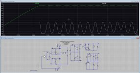
Using the Gap in the transformer for tuing is used a lot, but ferrite is quite hard, so the need of a diamond disc?
test sim in pic.
Attachments
https://vtechworks.lib.vt.edu/bitstream/handle/10919/28982/Ch5.pdf?sequence=7
nice read about transformers
nice read about transformers
Actually, you will not be using the gap for tuning, as it will only vary the magnetizing inductance of the transformer. The leakage/resonating inductance, which is used to set operating frequency, is generally established by the number of turns and winding geometry, which is why most XFMRS for LLC use have divided bobbins, with the primary in one bobbin 1/2, and the secondary/ies in the other bobbin 1/2. With some juggling, this can be used to establish the value of leakage inductance needed for a given operating frequency. Unfortunately, most of those divided bobbins are proprietary, or only available if you order thousands of them. I have improvised using epoxy-glass spacers glued in the center of the bobbin window. For conventional bobbins, it is generally easier to use a separate resonating inductor, with a conventionally constructed transformer, with a small gap to establish the required value for magnetizing inductance.
Kees-
I would recommend that you go to www.power.com and check out the Hiper-LCS product, which is an integrated solution for building an LLC DC-DC stage. The associated design software is very useful in putting together an LLC design, and has a provision for a separate resonating inductor. While you're there, also download application note AN-55, which has a lot of tips for bringing up and optimizing an LLC design.
I would recommend that you go to www.power.com and check out the Hiper-LCS product, which is an integrated solution for building an LLC DC-DC stage. The associated design software is very useful in putting together an LLC design, and has a provision for a separate resonating inductor. While you're there, also download application note AN-55, which has a lot of tips for bringing up and optimizing an LLC design.
Last edited:
The gap can't solve the problem of choosing the wrong core for your application .LLC proper transformers have very little physical gaps.The magnetic core by itself needs to be non-saturable within required power parameters.All llc relates back to 1959 Baxandall resonant circuit and the explanations given for that simple inverter https://en.m.wikipedia.org/wiki/Royer_oscillator
fits the modern llc theory very well because, while the leakage inductance can be obtained from the magnetic core and winding technique, it will provide a very narrow window of proper magnetic flux and an external inductor to make for constant current will always be a better option.Take a good llc power supply vs a cheap LED display one using no external inductor and see which one has the longer life!
https://training.ti.com/resonant-converters-wide-io-ranges
LLC transformers should have enough (just enough) gap for the proper ratio between magnetizing inductance to leakage inductance. The right amount of magnetizing inductance will allow ZVS operation, greatly reducing the power dissipation in the switches - too much magnetizing inductance, and you will hard switch. The Baxendall oscillator is a variant of a push pull converter (I have the original I.R.E. paper), and not necessarily relevant to LLC converter design.
There is actually a fairly wide acceptable range of operating flux density for an LLC converter transformer, unless you do something egregiously stupid like design a transformer with way too few turns, in which case you may have problems with saturation. Another way to fail is to choose a core that is too small to hold the the necessary copper.
I have many successful LLC designs under my belt, and the main concern is tweaking the design so that the actual magnetizing and leakage inductance of the transformer are represented in the design spreadsheet for predictable operation. This means that the LLC transformer design will generally go through an iteration or two before you get the real transformer. The design spreadsheet will give you an estimated value of leakage inductance given the number of primary and secondary turns you use. This may not necessarily be the same as the actual leakage of a real transformer, so it is necessary to wind up a sample first with the number of primary and secondary turns called out by the spreadsheet and measure it to find out the actual value of leakage inductance, which is then fed back into the spreadsheet for final tweaking. There will always be some uncertainty regarding the actual leakage of the transformer for an integrated transformer using a split bobbin as the leakage will be dependent on the physical construction of the transformer. This is not generally a BFD, and you can home in on a viable transformer and resonant circuit design fairly quickly.
If you use a separate resonating inductor, the design can be more predictable and straightforward, as then you are not depending on the transformer physical construction to provide the leakage/resonating inductance. The main transformer can be designed like a conventional transformer with minimal leakage inductance and a small gap to provide the proper amount of magnetizing inductance.Unlike an integrated transformer design using a split bobbin, you can use conventional magnet wire rather than Litz wire, as there is no huge amount of leakage flux present to heat up the adjacent wire. The gap needed to provide the proper amount of magnetizing inductance is generally small enough so that there is not a big problem with heating wire adjacent to the gap.
For an LLC converter with high voltage outputs, I would prefer a design using a separate resonating inductor, so that you can better deal with the large number of turns necessary for high voltage output - given the choice between many turns of magnet wire or many turns of Litz, I'll take the magnet wire any day, as Litz is a bona-fide PITA to handle. Magnet wire also has better volumetric efficiency as compared with Litz of the same current capacity, so magnet wire will take up much less room on the bobbin as compared to an equivalent Litz design. I would also opt for a design with a voltage doubler output, as then you only need to deal with a single winding. That way, phase-phase symmetry will not be a concern, unlike a conventional LLC output using a FWCT output configuration.That single winding will also have 1/4 of the turns needed for a FWCT output, another plus.
Last edited:
Nice discussion.
I have here reuse a transformer from a tv set, it does 450 watts. I need high voltage also and sometimes the LLC does not work well, I do not
use a power factor for this design because it is low power, so need a wider deviation of frequency.
the other transformer is dissassembled and the gap there was 0,75mm.
The transformer who is intact is 580uH and has leak of 180uH making a Lp of 580uH and a magnetic inductance of 400uH.
I have seen that there is a split capacitor who has a valeu of 9 nF (two series 18 nF). I get a Lr Cr resonance of 125 Khz.
For high voltage I bin told the LCC is a better option also because of better regulation on low load,s.
Maybe someone has a idea? a voltage doubler the best way, then I can stay below the 310 mains who give a much better regulation because I then need just 170 volts.
regards
Attachments
![DSCN5125[1].JPG](/community/data/attachments/1021/1021171-7dc42ab82541f95b3ee0fc58aa1e53b2.jpg?hash=fcQquCVB-V)
I think it would be useful to know the voltages and currents needed cause the thread started with a 1.2kwatt llc design and now we're told it is downgraded by the use of 450 watts magnetic core for a lcc design...
I can make a new tread, maybe diyaudio can move me there.I think it would be useful to know the voltages and currents needed cause the thread started with a 1.2kwatt llc design and now we're told it is downgraded by the use of 450 watts magnetic core for a lcc design...
Look, you are about two times off in terms of flux density - try 20 or even 15 turns primary. And the magnetizing problem is solved.
Gap is unreasonable to say the least. Check that:
https://www.tdk-electronics.tdk.com...d-accessories/cores-with-distributed-air-gaps
Gap is unreasonable to say the least. Check that:
https://www.tdk-electronics.tdk.com...d-accessories/cores-with-distributed-air-gaps
Hmm is some while ago, I have done now a LCC converter, that is much better for what I did want to do. for LCC no gap is needed but the LM need to be large because LCC is a current source type of tank.Kees-
I would recommend that you go to www.power.com and check out the Hiper-LCS product, which is an integrated solution for building an LLC DC-DC stage. The associated design software is very useful in putting together an LLC design, and has a provision for a separate resonating inductor. While you're there, also download application note AN-55, which has a lot of tips for bringing up and optimizing an LLC design.
- Home
- Amplifiers
- Power Supplies
- LLC Converter maximum gap in core