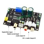
Recently, I bought a couple of small cheap Chinese DAC board, with CS8416/CS4344; the boards are intended for a simple low-cost system.
The output pins of the CS4344 are connected to the analog output of the board trough a first order low pass filter, similar to the one proposed in the IC datasheet; beyond this filter, there is a couple of transistor (Q1 and Q2) connected between each signal line (collector) and ground (emitter); I was not able to find where the transistor base is connected.
I can only suppose that this couple of transistors is used as a muting circuit, but I don’t understand the utility.
I tested each board feeding its optical port with the TOSLINK coming out from my CD player, playing Denon Audio Test CD; in the pictures, you can see the DAC board output waveform when reproducing a 0 dBFS sine wave at 315Hz and at 9999Hz.
There are two problems: the distortion in the lower part of the sine and a lot of “dirt” in the 9999Hz sine.
The distortion is caused by the external load of the CS4344 output (probably by the useless output transistor, maybe in inverse conduction?); the waveform at the IC pins is perfect (harmonics level is more than 70dB below the fundamental) when they are isolated from the filter.
The “dirt” on the waveform (I can’t find a better definition) has an amplitude that increases with the frequency of the reproduced sine wave and is completely absent without signal (trace “silence” of the Denon CD); the “dirt” has no components in the audible band (20Hz – 20KHz)
The 3.3V power supply looks clean; the second DAC board I bought behaves in the same way.
The only hypothesis I can do is that the CS4344 internal filters don’t work as they should and the “dirt” I see is the effect of the image frequencies.
Any suggestion regarding the cause of this behaviour and how to eliminate it will be appreciated.
Attachments


Did you ever find out how to modify this circuit ? I have 2 of these in an amp I built and want to improve the audio quality.
The OP did not show a picture of the subject. Maybe you could show a picture of the muting transistors?
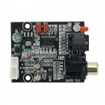
Hi, I discovered that this little board has another problem, that is the board doesn’t automatically switch the input between COAX and OPTICAL as a function of the applied signal; in particular if signals are applied at the same time to both the inputs (COAX and OPT), the analog outputs are ****.
So I decided to use another kind of board, this one
https://www.ebay.it/itm/174332972341?hash=item28970e0d35:g:0zwAAOSwMdVf~WW2
in conjunction with a four input selector (two COAX and two OPT inputs) using reed relays controlled by a rotary switch.
I’m very happy with the result.
So I decided to use another kind of board, this one
https://www.ebay.it/itm/174332972341?hash=item28970e0d35:g:0zwAAOSwMdVf~WW2
in conjunction with a four input selector (two COAX and two OPT inputs) using reed relays controlled by a rotary switch.
I’m very happy with the result.