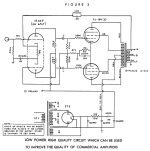
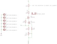
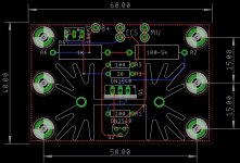
GRS PT6816 Improvements

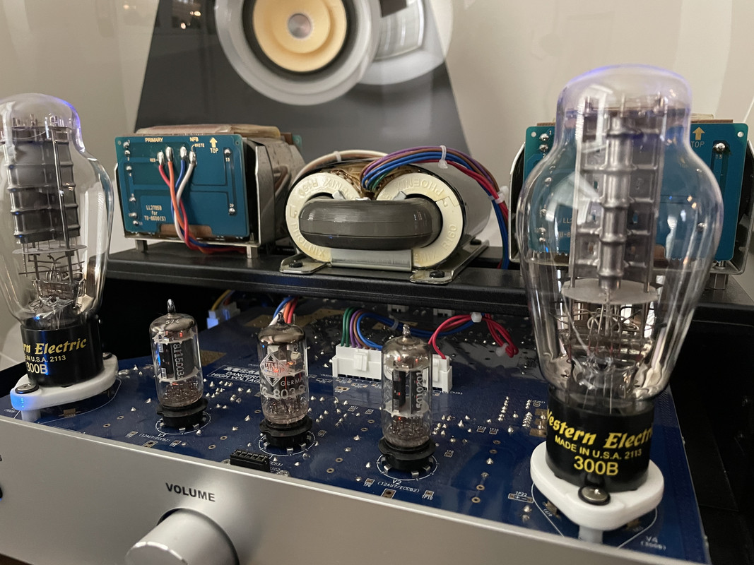
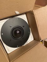
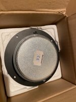
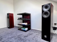
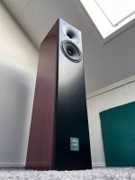
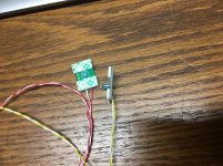
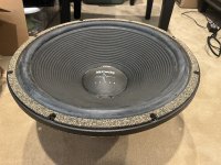
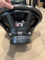
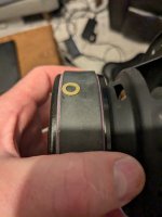
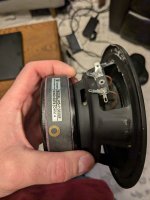
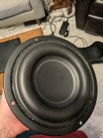
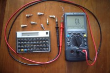
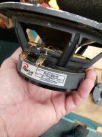
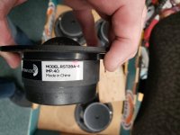
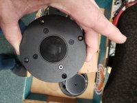
I recently tested a GRS PT-6816 and am very impressed with the performance. From the get go I was reintroduced to what I consider to be the superior sonic presentation of a true dipole compared with conventional drivers. This is further benefited by the minimal and non resonant enclosure of the driver. The GRS seems neutral and fairly well behaved. It exhibits minimal audible distortion playing loud crossed over at 400hz-20khz. I consider it equal in performance to the best 3" full range and mid woofers that I've tested. An advantage I observe in addition to its dipole radiation pattern, and advanced elegant design and construction, is that it is extended like true tweeter, more so than any of the 2"-3" conventional cone drivers that I've tested. Though conversely, unlike said conventional drivers, 400hz is certainly the limit of its lower frequency extension. In addition a point source is a preferable design to a line source in my opinion and thus I wouldn't endeavor to use more than one or two of said drivers per channel in my explorations.

I observe a harshness in the upper mids and highs at louder volumes when compared with the highest performing small cone drivers and or a dedicated tweeter. While the clarity and istrumentation is equal only to electrostatic transducers, there is also a seeming albeit slight lack of dynamism and three dimensionality to the sound that the GRS produces.

I wonder if both aforementioned observations are reduced or resolved through the incorporation of a more elastic membrane and conductor as I intuit that "Polyethylene Naphthalate" is quite rigid, seemingly similar to mylar or kapton tape. In the interest of reducing high frequency resonances of the membrane, increasing low end extension while maintaining treble extension, and increasing effiency, I suspect that the incorporation of a slightly elastic membrane and conductor would set a driver of this design in a class above the rest. What would be such a material for both the membrane and conductor? Even at present, the GRS PT-6816 is my driver of choice for a near midfield two way or three way design.

Hearing insects with ear pressure?

An odd thing happened last night. I was sitting in the living room with the windows open, and could hear the gentle night sounds. My ears felt a little stuffed up, so I did the old SCUBA driver trick of holding my nose closed and gently blowing. That worked. But I noticed that as the pressure increased, so did the sounds of the insects outside. I tried this several times (including right now) and could get about a10-12dB increase in the insect chorus. Strange. Other sounds were attenuated, only the high pitched insect sounds get louder as the internal pressure increased.

I have no idea why this works, and I have never noticed it before. FWIW, I live at 1300 meters above sea level.

Pop/click free HW-based relay attenuator V3

A little less than a year after I relased V2 of my attenuator, V3 is finally done and tested and it works absolutely perfect.

Description :

Fully HW-based pop and click free relay attenuator.

All done with some clever use of digital logic and accurate timing.

127 x 0.6dB steps for an attenuation range of 0 to -76.2dB.

High quality Omron G6K relays, high quality low noise, low distortion 0.1% Panasonic 1206 ERA Thin Film resistors.

Perfect channel balance, from max to min attenuation.

The attenuator needs a 10K termination resistor to maintain a 10K total attenuator impedance.

Use a 100K Linear potentiometer to adjust the ADC input voltage.

150mm x 40mm 4 Layer ENIG PCB.

Changes from V2 :

1. A few Bugfixes : No board level modifications are needed on V3. Q1 is now a Mosfet instead of a BJT.

2. Improvements : The board is now uisng an external on-board clock source instead of the built in oscillator in ADC0804. The built in oscillator circuit just isn't good enough.

3. Simplification : The detent function that stabilizes the circuit by using the LSB has been made simpler but it still works as intended.

4. Expandability : Stackable expander board(s), there is now an extra output header that can be used to stack additional boards on top of the main attenuator board.

Build tips :

The supply voltage to the board should be between 14-18VDC for the attenuator board alone and 1 expander board. This is enough to control a balanced/differential signal.

If using 2 or 3 expander board I would personally keep the supply voltage to 14-15VDC to keep the dissipation in U12 to a reasonable level(below 800-900mW.

When ordering componenets the majority of them can be supplied from Mouser but 4 of the Thin Film resistors should be oredered from Digikey. However, everyone is free to use whatever resistors they like, as long as they fit on a 1206 footprint. 🙂

It is not needed to order the 14 Pin Male Header if you are only using the attenuator for SE stereo signals.

2. Selecting Potentiometer : Almost any 100K Linear potentiometer will work, but I personally use this one from Bourns :

Mouser : 53RAA-R25-A20L Bourns | Mouser Denmark

Digikey : 53RAA-R25-A20L Bourns Inc. | Potentiometers, Variable Resistors | DigiKey

Ordering: The price is 20$ per PCB and I only have a small batch available

Shipping is 5$ anywhere in the world. Additional shipping charges may apply if the number of PCB's ordered exceed the weight limit for 5$ shipping.

Send me an E-mail with your DiyA username, real name, adress and E-mail adress and I will send you a PayPal request. Since this is a hobby it might take me a day or two to reply and a few more days to ship. I hope people can live with that.

EDIT : The component placement drawing is not 100% correct, the CON1/CON2 connectors are actually 5mm more to the left than what is shown.

Attachments

Helloworld.exe

Hi all!
My name is True Taylor
I started my speaker journey back in 2003 as part of the work/study program my Junior year in High School. I was always into tech stuff as a kid, and a position opened up at Toby Speakers in Fort Worth, Texas. (Just across downtown). I realized fairly quickly that I learned much faster on the job, and enjoyed myself significantly more with an open slate to do whatever crazy things came to mind. I skipped a college experience, as schooling never really suited me.

After nearly 10 years of building speakers and taking over more and more responsibility at the shop, I ended picking up the mantle for Toby Guynn, and am carrying on his legacy.
I may add more to this post later if anyone cares to hear about my background, but I'm now 22 years into designing and optimizing speaker systems from scratch. I have a small workshop just outside downtown Fort Worth (Haltom City, TX), and continue to build and design new systems. I have an in house CNC that I operate, a multitude of 3d printers and other tools to assist with any custom projects I am working on, and a very wide array of experience to assist in the endeavor. I currently share the 9k sqft shop space with a friend that tunes cars (and have a dynomometer in the back of the shop for doing so). I am also very much into silly cars and high horsepower (mostly Turbo inline 6 vehicles - I have 3 😛 )

In the last few years, I have moved from optimizing low cost home systems and car subwoofers into assembling some of the highest quality components I can into truly magical experiences. I am now utilizing components from Purifi, Satori (Such Sweet Beryllium 🙂 ), and Hypex amplifiers. Finding the limits of those components, and wanting very much to build LINE SOURCE systems, I was finally able to dedicate the time toward building our first production ready Electrostatic speaker systems. With an impossible amount of assistance from a forum member/long time friend/ESL expert/all around great guy, I have created some really neat architecture and learned to produce a viable PCB Based solution.

I'm mostly here to learn, and help others with anything I might have insight in. Anyway. Cheers!
-True
  • Like
Reactions: rsavas

Wanting to use the lowest noise transistors I can in this Sony STR-6055

I’m rebuilding a Sony STR-6055 that’s a bit of a problem child. I’ve started on the amplifier driver board first and I’ve already found two transistors with a short. So far the replacements made are all of the 2SA706 and 2SC1124 with TTA004b and TTA004b. The rest of the transistors are to92 packages, 2SC632A, 2SC634A, 2SA678 which happen to be higher gain transistors with high-ish current spec for a to92.
I pulled a couple 2SC634 from the board and they measured with a gain of 404 and 421 on a Peak DCA75. Ultimately the KSC1845 matches perfectly with the exception of the 50 mA current rating vs the original 200 mA.

So being circuit dependent of course I’m trying to figure out where they would work.

I’m guessing that here in the phono preamp and tone amp that the current would be low enough that the 1845s would work well here.
IMG_3898.png


My concern mostly is in the amplifier.
The differential pair is another place that has pretty low current demand on the devices correct? So 1845s there?
IMG_3899.png


What about Q704, Q705 and Q706? They have Q705 listed as a 2SC1124, but it’s actually a 2SC634A in circuit.

Are my thoughts correct on all of the previous transistors (preamp and differential pair on amp board)? If so I guess my question pertains to these last three then.

Another option I have is BC550C and BC560C. Though some don’t consider those low noise.

Thank you,
Dan.

Hi!

Hi!

I am from small galaxy named "Eesti" (Estonia). Member of this site some years.
but quiet because I don't consider myself smart and I can't express myself perfectly in English.
today it is possible to use steroids for expression(steroids named Google)
and I need to say something about some subject. does that mean i'm now smart? no!
i am 60 and still little boy learning everything.

My main interests on audio electronics fields are: how to preserv "recorded holografics and tone"
and how to cook DA converters, TDA1541A in first place, but not only.
  • Like
Reactions: Speedysteve7

The Aletheias

Introduction
Up until now I've been mostly using mid-tier drivers and crossover components. This time I wanted to try higher-end components, to see if more expensive means more better (I'm generally skeptical about the relationship between price and performance, especially in audio).

The name (Aletheia) is derived from Greek mythology. Aletheia was personified as a Greek goddess as an embodiment of disclosure or the uncovering of truth. This fits neatly with the 'Revelator' product line of Scan-Speak (these drivers were used in this project).

Design goals
  • A 2-way floorstander that sounds AND looks great
  • Linear response (40 Hz - 20 kHz ±2db)
  • Controlled directivity
  • Good phase integration
  • Low distortion

Midbass selection criteria
  • Linear response
  • Minimal cone breakup, and well above the crossover frequency
  • F3 < 40Hz
  • Box size < 40L (for QB3)
  • Good sensitivity

Tweeter selection criteria
  • Linear response
  • Low distortion (limited data available, using low Fs as an indicator)

For the midbass I chose the Scan-Speak 18W-8531G00. It has a nice combination of low-end extension, reasonable box volume (for a QB3 alignment), and sensitivity. Also, due to the paper cone, breakup is very mild. For the tweeter I ended up with the Scan-Speak D2905-950000 for its linear response, low Fs, and low distortion (as measured by AudioExcite). To which I mounted a Monacor WG-300 to control directivity, improve phase integration, and minimize edge diffraction.

The downside to adding a WG to a non-WG tweeter is of course that the response becomes very non-linear. The sound pressure increases at its lower frequencies (acoustic energy gets more focused), tapering off as frequency increases and radiation becomes more narrow (effect from the WG decreases). But this can be corrected in the crossover design. The WG was mounted to the tweeter using a custom adapter made from 9mm MDF.

I used WinISD to calculate the cabinet volume and port dimensions. I started from the QB3 alignment, but slightly reduced the cabinet volume trading a bit of extension for slightly reduced group delay. I ended up with a 35L cabinet and a theoretical -3dB at around 34Hz.

After building the box and mounting the drivers I measured each driver (gated farfield) using REW. Looking back I regret only taking measurements up to 60° off axis. I used the measured responses and impedances to design a crossover in VituixCad.

After much fiddling and a lot of help from my brother I ended up with a 3rd order on the tweeter and a 2nd order on the midwoofer. The crossover frequency is at 2100Hz, with good phase overlap around this frequency, and a decent match between the directivity of both drivers. I also incorporated an impedance correction network to mitigate a large impedance peak around the crossover frequency, which should make the speaker suitable for amps with a lower damping factor (like tube amps). I used coils (all air core) from Jantzen and Mundorf, Clarity Caps for all caps, and a Mundorf MOX resistor for tweeter attenuation.

For the finish I used a padouk wood veneer. As this type of wood is very sensitive to UV and I wanted to prevent it from greying, I applied multiple layers of UV-filtering high-gloss polyurethane. The baffle is finished using a satin black paint (many layers, with lots of sanding in between).

I'm very pleased with the result. Instruments and voices sound very lifelike. The low-end extension is impressive, but other than that it's very natural in its presentation, without emphasis on specific tonal regions.

To be honest, this experience won't stop me from using mid-tier components in the future. For me, the perceived difference in sound quality doesn't justify the difference in cost. Another factor is that I enjoy building speakers as much as listening to them (maybe even more). But I had a lot of fun building these, and will probably be using them as my main speakers for a long time.

Attachments

  • Glueing 3.jpg
    Glueing 3.jpg
    544.7 KB · Views: 143
  • Polyurethane.jpg
    Polyurethane.jpg
    633.7 KB · Views: 141
  • Result 1.jpg
    Result 1.jpg
    272.8 KB · Views: 141
  • Result 3.jpg
    Result 3.jpg
    274.6 KB · Views: 143

A surprising and worthwhile upgrade for my USB DAC.

Some time ago I bought an Xduoo MU-604 to replace my old USB powered DAC, an Arcam R-PAC.

I was very pleased with the upgrade as the R-PAC allowed hash through from the PC and the XDuoo with its own outboard PSU didn’t.

I did try a USB isolator and it did work well, but only in low speed mode. I felt that the R-PAC always sounded much better in high speed mode.

Anyway, I recently purchased a Camera Adapter for my iPhone that allows me to use an external USB DAC. This works for all data rates and is great for having a music streamer that is silent unlike my tower PC.

It occurred to me that I should try the R-PAC with this too, so I did. There is a pleasing lack of switching noise using the Camera Adapter since of course the phone runs on batteries.

The R-PAC sounds very very good used like this. Is it as good as the XDuoo? Not sure, but it isn’t far away. I need to switch back and listen some more.

I never expected an inexpensive adapter like this could be such a positive influence on sound quality - not because it has magical properties, but it allows the DAC to work at its best without all the ground noise from the PC.

I don’t know if the android phones have an equivalent device, but for folks that have noise from USB powered DACs this is a cheap and effective solution and gives my venerable R-PAC a new lease of life.

Has anyone had a similar experience?

PCM63P legit?

Hi, I have an offer for PCM63P that look like this. Searching the net I have only found one picture in which the production data and batch number are printed vertically like the offered chips have. The offer is from a small electronics company, which has them laying around for a long time they say.
Does anyone know if in the final years of production, this printing was used by BB?

Thanks

1730469765625.png

What low Rp output tubes, like 1K or under, for a 3.5K SE OPT?

I have a nice pair of SE 3.5K OPTs, but no 4 ohm tap so I'm stuck with 3.5K. I want to use a higher gain tube in triode so I can use a lower gain driver. So not 2a3 or 300b.

I usually use trioded EL6 and EL12 types into 5K but they're 1.1K Rp and not so good into 3.5K. I was wondering about KT88 or 6550 but I read that they make poor triodes - no idea how true this is. Data suggests they're around 900ohms Rp in triode.

PSE is possible with EL84 or 6V6, which would come out at around 1K, but I'd prefer a single tube in triode. Looking for a dissipation of around 18W.

Canadian Introduction

Hello everyone,

I've been a traveller for many years, moving from country to country, working little jobs where i went to pay for rent and food, after some 10 years of moving around the world, i settled in Canada.

I had alot of belongings i had put into storage while i travelled. in this storage was a pair of wharfedale III floor speakers from 1971, moving them to canada, and getting a system up and running was a bit of a mini dream for me, these speakers have been in my life for many years and I've never really got a chance to use them.

recently i've got them up and running with a quality amp. listening to music on them is simply magical.

I need help with repairing the woofers, the edge gasket has started to crack. i realised that the gasket has become very brittle, most likely due to age and being in storage for many years, then being boated around the world in frigid cold.

anyway, I'm a techy, I like fixing electronics and repairing things. when i seen that my speakers where in need of some first aid, I went searching for help online and found your forums.

Thank you for having me.

Pat
  • Like
Reactions: dantwomey

For Sale DIY LIGHTSPEED ATTENUATOR PARTS

All parts are new
2 blank PCBs (one has the 4 resistors installed)
KEMO LED tester
21 Silonex optocouplers
TI IC linear regulator 5V
4-1K Ohm trimmers
strip of 100 Ohm resistors
1-10 uF electrolytic capacitor
2-.1uf WIMA film caps
5 WAGO PCB terminal blocks and tool

diyaudio.com/forums/group-buys/153388-optical-volume-proofessional-pcb-11.html
diyaudio.com/forums/analog-line-level/80194-lightspeed-attenuator-passive-preamp.html

$75 plus $18.40 Priority Mail shipping in CONUS.

Thanks for looking
MtempImagegB6eYR.giftempImagesmEsxU.giftempImagee43FXy.giftempImagengtkbV.giftempImageUmomub.giftempImagetRQKca.giftempImagebSydkt.gif

Attachments

  • tempImagetp2PjF.gif
    tempImagetp2PjF.gif
    1.5 MB · Views: 1,520

F1 or F1J Amp and Power Supply Boards with UMS Mounting Pattern Group Buy

I made up some boards for the F1/F1J amp this past summer and fall (a bit of the history is documented in the "Firstwatt F1J" thread). I sold the extra boards from my order to others following that thread, and so far three amps have been successfully built. There have been more requests for boards than I had made up, so I am posting a group buy to see how many to include in a second order. Here are a few details about the boards. Prices below do not include shipping, I will charge actual shipping costs to your location via USPS, which has been about $8.40 in the US and $14.50-$37.50 outside the US.

If you are interested, please copy the text line below and fill in the your diyAudio user name and the quantity of each item you would like and place it in a post replying to this thread. On Dec. 6 I will start sending pm's with my paypal information and the total cost for your boards + shipping. I will place the order for boards on Dec. 13 and expect to start shipping boards out from my location in early January.

Text to copy in your reply:
username, x pairs of amp boards, x power supply boards, x pairs of bridge rectifier boards, x pairs of led mounting boards

F1/F1J Amplifier Boards $15 per pair
- 2oz Copper with ENIG construction
- green solder mask
- Hole spacing and transistor mounting per UMS specifications to work with diyAudio predrilled heatsinks
- All power trace widths maximized and two side routed
- Multiple mounting options for various types of input caps, including terminals for caps too for on board mounting
- Additional resistor locations and potentiometer added to original design for setting DC offset

Power Supply Boards $6 each
- 2oz Copper with ENIG construction
- green solder mask
- Hole spacing on 10mm pitch to match hole spacing in diyAudio "base plate"
- On board mounting of thermistors for in rush current limiting and ground lift functions

Discrete Component Bridge Rectifiers $4 per pair
- 2oz Copper with ENIG construction
- green solder mask
- Hole spacing on 10mm pitch to match hole spacing in diyAudio "base plate"

LED Front Panel Mounting Boards $1 per pair
- 1oz copper with Lead Free HASL construction
- green solder mask
- Just a convenient way to mount the front panel led's with double sided tape

The photos are the boards from the first order, and the screen captures are the slightly "improved" boards for the group buy.

Attachments

  • F1 Amp PCB.jpg
    F1 Amp PCB.jpg
    931.3 KB · Views: 1,046
  • F1 Power Supply PCB.jpg
    F1 Power Supply PCB.jpg
    913 KB · Views: 1,005
  • Bridge Rectifier.jpg
    Bridge Rectifier.jpg
    1 MB · Views: 969
  • LED PCB.jpg
    LED PCB.jpg
    380.2 KB · Views: 925
  • IMG_5510.jpg
    IMG_5510.jpg
    998.3 KB · Views: 935
  • IMG_5542.jpg
    IMG_5542.jpg
    1 MB · Views: 530
  • IMG_5908.jpg
    IMG_5908.jpg
    1 MB · Views: 496
  • Overall.jpg
    Overall.jpg
    946.9 KB · Views: 540
  • F1 Amp V3,6.PNG
    F1 Amp V3,6.PNG
    136 KB · Views: 552
  • Power Supply V2,1.PNG
    Power Supply V2,1.PNG
    184.2 KB · Views: 431

How much comparable power do we need for different frequencies?

Does anyone know how much power we need for each frequency? I mean, I wanna know, how much relative power do I need for 20hz, 30hz, 50, 100 ...

Lets say; at 20hz, for each additional 3 db, I have to double the power comparing 30hz

for 30hz for each additional 3db, I have to double the power comparing 40hz.
..... etc.

I hope I could explain 🙂
  • Like
Reactions: cracked case

TPA3116D2 BSNL pin

Hi All,

I am finally working on a my first amp with TPA3116D2. Could someone please explain the purpose of BSNL pin on the chip?
The datasheet says the following:

Boot strap for negative left channel output, connect to 220 nF X5R, or better ceramic cap to OUTNL.

Similarly, BSPL defined as the Boot strap for positive left channel output, connect to 220 nF X5R, or better ceramic cap to OUTPL.

but I have no idea what is the meaning of "boot strap" in this context.

For the reference, the datasheet is available here: https://www.ti.com/lit/ds/symlink/tpa3116d2.pdf
Thank you!

Greetings from a retired wedding DJ!

I recently retired from DJing. Sold my EV Tour X speakers and QSC amp. I kept my 2 12" active EV Live X speakers that I use for odd jobs here and there. The other day the Parts Express catalog showed up in the mail. It was full of raw drivers and now I have the itch to build some subwoofers to pair with my Live X's. I think I have settled on the SS15. If only drivers were still as cheap as when that original SS challenge started!

BGW GT series AC to DC fan conversion

I have a pair of BGW GTB's with both having worn out fans, as I intend to use them in a living room the original 120VAC 107CFM fan wasn't useful anyway. I plan to use a 120mm PC fan, something in the likes of a Noctua or Noiseblocker to provide at least some airflow through the case.

I have the schematic of de GTA which is the same except for a second power supply. There is a 12VAC secondary used to power the delay circuits of both channels that I could tap the power from for an AC-DC converter.
Would such thing work without causing damage to the circuit? There is also plenty of space inside the amp.

Schermafbeelding 2024-10-23 201959.png

Hey!

Hey people!
I've been reading this forum for years. I learnt lots of very useful information. I have small shop of used synthesizers. And I have to repair them from time to time. Also I am musician and sound engineer. I have home studio built to satisfy AES standard for control rooms (well, almost satisfy). Finally I have question about my Event Opal studio monitors, so I decided to register after all and ask.
I hope this is ok for an introduction =)
Since I mostly repair synthesizers and my DIY is mostly about carpentry and building. There is not much I have to say about my audio DIY background.

Dynaco 6V6 PP to guitar amp

hello guys

Some time ago I built this amplifier, from a Dynaco schematic, it is a stereo 6v6pp, the question is, what should I change to make it work for guitar? I don't know what impedances guitars handle but I would appreciate if someone could guide me a little. thank you so much!!

Attachments

  • Push-Pull-EL84-6BQ5-6V6-6AQ5-Dynaco-A-410-Tube-Amp-Schematic.png
    Push-Pull-EL84-6BQ5-6V6-6AQ5-Dynaco-A-410-Tube-Amp-Schematic.png
    40.3 KB · Views: 144

New to this schematic question...

I'm doing the layout for a 2A3 Loftin White style amplifier. My question is pretty straightforward and probably obvious to those with any amount of experience. Is the circled section of the schematic (see attached) repeated on both channels? I would assume it does but I was looking over a Japanese audio magazine and saw some similar filtering in a different/unrelated schematic and that section appears to only be implemented once.

Thanks in advance!


Untitled_Artwork 2.jpg
IMG_3665.jpg
IMG_3664.jpg

CKT-TF1525e System build

I'm about to start making a pair of celestion TF1525e speaker boxes (https://celestion.com/wp-content/uploads/2019/10/188.pdf) and was wondering if anyone had attempted making these before and had any specific tips on making them, or if anyone had more general advice on speaker cab construction.

For the panels, I'm going to get them cut on a cnc machine to keep the edges nice and straight. I'm either going to use the recommended 15mm birch plywood, or an alternative to birch as its quite expensive at the moment. To secure the panels together I was thinking of using wood glue and countersunk screws to increase the grip between the panels (is this nesacery or will just standard brad nails work instead?). I'm going to leave the finish as exposed wood instead of painting so will need to apply some hard wearing varnish on them so that they don't get banged up as easily. I might look to make some stands for them as well as this is the recommend positioning for them (but I might also jsut use them on a table depends how lazy I'm feeling).

For making the crossover I'm going to use the plan shown on the link above, although one part of it has confused me a little. On the design C1 and C2 are shown next to each other but with a "/" in between. Does this mean that the values are interchangeable or will I need two capacitors for the low pass filter? Also on the diagram for C2 the value is in uH instead of uF, I'm guessing this is just a typo though and I'm just going to use a uF value instead. For the inductors I haven't really been able to find ones of the exact values so I may have to buy some larger ones and uncoil them to get the right value, does anyone have any experience of doing this and know how to get the best results? I've also drafted up a components list of what I'll need for the crossover:
LF:
L1: https://www.bluearan.co.uk/index.php?id=CNVACLD180 - potentially use a core from willys hifi -https://willys-hifi.com/
C1: https://willys-hifi.com/products/mkp-polypropylene-hifi-crossover-capacitor-10uf-250v
C2: https://willys-hifi.com/products/mkp-polypropylene-hifi-crossover-capacitor-2-2uf-250v
R1: https://uk.farnell.com/arcol/hs25-1r-j/resistor-wirewound-1ohm-5-axial/dp/2478173?st=1ohm resistor - more on https://willys-hifi.com/collections/resistors-20-watt

HF:
L2: https://www.bluearan.co.uk/index.php?id=CNVACMC072 - will need to uncoil to give desired value - potentially use a core from willys hifi -https://willys-hifi.com/
R2: 12 Ohm 20 Watt 5% Ceramic Wirewound Resistor - Willys-Hifi Ltd - more on https://willys-hifi.com/collections/resistors-20-watt
R3: Jantzen Superes 10W 100 Ohm 1% Crossover Resistor - Willys-Hifi Ltd - more on https://willys-hifi.com/collections/resistors-20-watt
C3: https://willys-hifi.com/collections...lypropylene-hifi-crossover-capacitor-1uf-250v
C4: https://willys-hifi.com/collections...propylene-hifi-crossover-capacitor-6-8uf-250v
P1: https://cpc.farnell.com/raychem-te-...-radial-1-35a/dp/FF02433?ost=1.35a+polyswitch

Please refer to the link at the top if the component acronyms don't make any sense.


I think this post covers my basic prebuild understanding of the design and how I will execute the build, if anyone has any tips to add or things that I should be considering which I haven't mentioned then please let me know. Otherwise just wait for more posts to show progress updates on the build!

Frustrated B&O owner saying hello

Hi all,

I live in the UK and have been into "hi-fi" for many years starting with an old Elizabethan stereo record player back in the in early 70s. This particular model, whilst not very "hi-fi" did introduce me to the joy. if you can call it that, of repair as it used to blow its amplifier chips quite regularly!! After a number of different systems over the next 15 years or so I managed to save up to buy a B&O 3300 system; first used with small Celestion LS10 book shelf speakers and then Mission 774 floor standers. This lasted me until about 2006 when I replaced it with a Cyrus 6vs integrated amp and CD player. After a couple of years I added an Cyrus 8 power amp. The CD player lasted until 2020 when it failed to read CDs again so I replaced it with a Rega Apollo CD player.

After I retired the B&O system to the attic for about 20 years (I now know that was a big mistake leaving it there for so long) I'm trying to get it working to use it in a spare room. Record player works fine as does the amplifier/tuner at present, but the CD and tape there lies another story 🙁🙁🙁

time to start giving things away — Horn Tweeters

I have totes full of take them away drivers.

Horn tweters first. All vintage. I hope someone can restoration or creating something useful.

If someone expresses interest i will test them. To have gotten this far they probably all do.

Everything is free. Pick-up or you pay the post. Donations accepted. At some point in time what is left will go to a charity/thrift shop.

MoreTham1-hornTs.jpeg


3 x BIC horn + leftovers of a forth
2 x Pioneer tweeter
2 x Sansui tweeter

Foster-Zenith-Ts.jpeg


Foster horns as found in Zenith Allegro. 5 long ones with square bezels, 2 with the newer round bezel, 2 short ones

singe-hornTs.jpeg


singles. 3 variations on the Jensen, 2 short Radio Shack horns, another 1 similar to the" Jensens”

PPiezoTs.jpeg


All Peizos, there are 4 of the silver ones + 2 singles in front.

dave

4VRMS XLR level and TPA6120 max differential input voltage rating

I'm designing a DAC + HPA based on TPA6120 with the XLR output level of 4Vrms and PSU voltages of +/-15V. I'd like to use TPA6120 in a differential configuration (see attached TPA6120 circuit) taking an input differential signal directly from the XLR output after a XLR LPF (see attached XLR circuit).

I noticed that the absolute maximum differential input voltage rating for TPA6120 is 6V (see attached TPA6120 Absolute Maximum Ratings table). I assume it's 6Vpp, not 6Vrms.

Questions:
1. When a DAC spec for XLR output level claims 4Vrms, does it mean that each individual V+ and V- XLR lines should have 2Vrms level w.r.t. ground?
Then, 2Vrms * 2.82 = 5.64Vpp level on each of V+ and V- XLR lines w.r.t. ground?

2. If there would be 5.64Vpp level w.r.t. ground on each of V+ and V- XLR lines, does it mean TPA6120's differential inputs could potentially see a max voltage of 5.64Vpp * 2 = 11.28Vpp?

3. Since the 11.28Vpp differential inputs voltage is higher than the absolute maximum differential input voltage rating for TPA6120 of 6Vpp, both the XLR lines should be attenuated down about 2x times. It will make them to be around 2.82Vpp w.r.t. ground each. If so, what could be a good schematic for the attenuator?

I might be wrong on some or all of those assumptions above 🙂 Any input\ideas are highly appreciated.

Attachments

  • XLR_circuit.PNG
    XLR_circuit.PNG
    54 KB · Views: 112
  • TPA6120_circuit.PNG
    TPA6120_circuit.PNG
    63.4 KB · Views: 96
  • TPA6120_Absolute_Maximum_Ratings.PNG
    TPA6120_Absolute_Maximum_Ratings.PNG
    86.6 KB · Views: 88

Soundcraftsmen RA7502 - Looking for info

I have a Soundscraftmen RA 7502, just given to me by a friend. He has not powered it up for years.

The A channel Looks OK, but the B channel has 800 mV Dc offset on the output. It will pass a 1K sine wave AOK, but rides on the DC offset

I am just starting to dig into it, and find that info is hard to find. Nothing on hifiengine. I found a blurry schematic on AudioKarma (attached)

Are there any Soundcraftsmen Gurus out there who have literature? Schematics, layouts, service manual?

F

Attachments

  • predriverRA_200dpi_new.png
    predriverRA_200dpi_new.png
    73 KB · Views: 142

OEM car amp keeps blowing fuses

Hi,


I have a OEM car amp that keeps blowing fuses. This amp in perticular has 2 x 25 amps fuses. (in fuse box, not in PCB circuitry )

Both fuses blows directly when new fuses are inserted and power goes on.

I know that it might be hard to tell what the exact cause would be.

PCB is surface glued but not too hard to remove.

So im satisfied with your "best guess" at this moment.

My guess is that it would be some component close to the power input. this since the issue affects both fuses.

Below is the PCB front / back.

Thank you !


IMG_7119.jpg
IMG_7120.jpg

McCauley 6174 H/T alignment

More of a just rambling thread… I have had this 6174 for quite some time and have never gotten around to using it. My last H/T sub stage was IB with 2 18” XBl2 subwoofers from Adire Audio. We moved into a new house and they stayed with the old home.

Anyway, I have plenty of room for a large 4th order vented alignment and was planning on about 12ft3 and tuning low, around 18-20hz for this driver. Amplitude response looks quite flat like this and efficiency is high. I have a single Adcom GFA 555 to power it with, so that should be plenty in a box this size.

Has anyone ever played around with this driver in non-Pro Audio application? I have used many in the past for large format theaters, but never a small H/T.

Attachments

  • IMG_6460.jpeg
    IMG_6460.jpeg
    571.8 KB · Views: 80
  • IMG_6461.jpeg
    IMG_6461.jpeg
    509 KB · Views: 88

Does anyone use the Comtrue CT7601?

The default firmware is working fine then i want to try modifying it but currently i having hard time to understand firmware code. Seem like they define usb_regs in external ram to store register data. In the register table list, they devide into different banks and in each different bank they list register with index according to that bank. But seem like to change register setting, they use command McuWriteReg(0xA5, RecInFreq); which equivalent to usb_regs[0xA5]=RecInFreq;
Seem like firmware writer know position of each register and has nothing to do with register bank. Does anyone know how to know the register position? Or maybe i missing some doc from Comtrue? Thanks!

Aikido LV channel imbalance

I’ve been running an Aikido 24V preamp (6GM8) but only recently came around to trying to fix an annoying channel imbalance.

Output on the scope is as per photo. I’ve changed tubes around with no meaningful effect (switching channels) but the issue doesn’t seem tube related.

B+ is 24.2V, coming from a Salas regulator (probably overkill here). I see voltages across the circuit being 0.2V lower one one channel. Checked the caps (fine), measured resistors in situ (fine), reheated solder joints, disconnected the headphone driver circuit (R19). All to no avail…

Any ideas?
IMG_0258.jpeg

Acurus 200x3, repair or gut?

I just purchased an old Acurus 200x3 off Ebay. The unit was dropped, and only 1 channel is working. I was going to repair it when it arrives, but I really only bought it for the chassis. My DIY 2 channel amp is a Rod Elliot P101, I really like the sound and power. If I go the route of building 3 more P101's, What size of toroidal transformer would I get away with? I have a 800va 40 +40 in my 2 channel, that I would switch to the 3 channel if that is large enough. I would then get a 500va for the 2 channel ? The units are mainly for my theatre room and play 30% music also.

Attachments

  • 4914.jpeg
    4914.jpeg
    425.1 KB · Views: 163

Bessel and Butterworth 4th order alignments

These alignments are talked about in the Loudspeaker design cookbook and described as "Discrete alignments" that basically wiork only for one Qts value for any given Ql or box loss factor. I computed the values of Qts, alpha=Vas/Vb, H=Fb/Fx, F3m=F3/Fs, F10n=F10/Fs for values of Ql from 3 to 1Million 😉 for both bessel and butterworth alignments.
As a bonus, I compare the values given by QB3 and SC4 alignments for woofers with a Q of 0.32 - similar to a Bessel aligned woofer. FWIW, QB3 , SC4, and B4 alignments are all identical the B4 value of Qts.

The value of the Bessel alignment is that it has maximally flat delay and a lower F10 than either QB3 or SC4.

Attachments

  • B4 vs Ql.png
    B4 vs Ql.png
    12.7 KB · Views: 122
  • Bessel4 vs Ql.png
    Bessel4 vs Ql.png
    18.3 KB · Views: 115
  • Comparison BE4 with QB3 SC4.png
    Comparison BE4 with QB3 SC4.png
    2.7 KB · Views: 93
  • Like
Reactions: EarlK and Arez

Weird washer on driver magnet

I took out the TangBand W5 out of the bedroom 3 way to do some tests

I found this strange washer attached to the magnet. Is this part of the driver somehow....?

It looks brass but is magnetic. I have hundreds of washer types in my shop but none of them look like this.

Attachments

  • PXL_20241029_002422557.jpg
    PXL_20241029_002422557.jpg
    338.7 KB · Views: 188
  • PXL_20241029_002432036.jpg
    PXL_20241029_002432036.jpg
    380.9 KB · Views: 186
  • PXL_20241029_002425172.jpg
    PXL_20241029_002425172.jpg
    429.6 KB · Views: 182

What power supply would I need for this John Linsley Hood Phono Pre-Amp?

Hi Guys,

I found this "remake" of an old 70ties classic on PCB Way of an John Lindsay Hood 1450:

https://www.pcbway.com/project/shar..._Preamplifier__MC_MM___Turntable_Stylus_.html

Ordered the PCBs and parts. But I actually have no clue what kind of power has to go in. The original used a +14 / -14V power supply. Here I can see a rectifier on the board...

Can anyone help here?

Attachments

  • Screen Shot 2024-10-25 at 11.24.44.png
    Screen Shot 2024-10-25 at 11.24.44.png
    573.3 KB · Views: 114

I want to learn preamplifier design

Hy,
I have a need to design a preamplifier with no gain increase, fixed eq curve, followed by 2 tone control & volume control.

I had build preamplifiers before, but by schematic or designed by other members; This time I would like to actually learn how to design a preamplifier.

I know that I need to know input & output impedance, how much gain is needed, balanced / unbalanced, single/dual rail, what other functions are needed...
I would use LS Spice for simulations.

My plan is to find an eq curve via computer (line in - line out) and replicate it as much as I can.
By ear, I need mid tones boost, curve will probably look something like this:

eq mids.png

I would like to use NE5532 / TL072.
I still need to do a research on how to find / measure the impedance, but I will have 2 input sources, mono, power supply is not determined yet at this stage.

Now I will try to arrange the stages, please correct me as there will surely be an error.

1.) BUFFER (to avoid input impedance differences) -> 2.) calculated PASIVE BANDPASS FILTER (to lift the mid tones) -> 3.) GAIN STAGE (to get back to the gain, that passive filter took) -> 4.) ACTIVE TONE CONTROL (is this passive filter followed by gain stage? ) -> 5.) VOLUME POT (rather at the end than at the start of the chain, so it can also attenuate any hiss / buzz).

Does this sound correct? Should 3.) GAIN STAGE be moved just before the 5.) VOLUME POT, so 4.) ACTIVE TONE CONTROL can work with lower gain, reducing need of higher voltage from power supply? In this case would I need another buffer to avoid interference between 2. calculated BANDPASS FILTER & tone control?

Also if I would need mid boost and LFP for example, can this be done in one stage or do I need to make two stages? also for example if I would need boost at for example 500Hz and also at 2kHz, can this be done in single stage or do I need two? (Concern of 2 passive filters interfearing each other... again)

eq mids & lpf.png

eq curve 3.png


I know that I need to use coupling capacitors on inputs / outputs, to filter out DC, as far as I understand only concern in choice of such capacitor is cutoff frequency, so capacitor don`t filter out anything audible.... is there anything else?
Probably input / output impedance must be taken into account, to calculate capacitor value, but around 1uF would be the ballpark value?


This would be it for now, I still need to do some research about various factors, later I would come back with more questions as needed.


Thank you for your time 🙂

Bonsai's X-Altra HPA plus chassis, PSU and toroid

This is a very nice setup. The X-Altra HPA by Bonsai is very good, combined with the Golden Reference PSU and a quality toroid will make a cracking HPA.

The chassis is optional of course but is extremely high quality and built like a literal tank. This is the chassis from AliX

The PSU is part built in pic but will complete to 90%, the buyer will need two voltage references. Other PSU boards are available if preferred.

Transformer is 115 / 230V ac input so can go anywhere 🙂

Price for X-Altra HPA plus PSU - £40 plus shipping,

Chassis - £40

IMG_0967.JPGIMG_0968.JPGIMG_0969.JPGIMG_0970.JPGIMG_0971.JPG


Also have a couple Marsh HPA PCB kits with matched Toshiba BJTs and a balanced Dynalo kit left

Diagnosing strange pop, cracks at the begginning of playback

Hello


I have a CD player connected to a balanced amplifier via an xlr cable. The xlr output on the cd player hasn't been used for about 10 years or more.
My problem is that when I turn on the equipment, crackling appears, but it is worst at the beginning when I listen to a CD. Later, when the equipment has played for an hour and there are no more crackling noises or only few.

What could it be?

cheers Newman

Self Inverting Push Pull 6V6S Mono-Block Amplifier with tip socket test points

I designed and built this low power amplifier to drive an Usher S-520 two way speaker at my computer desk (near field, 2 feet speaker-to-ear).
With the bottom plate back on today, I am enjoying listening to a Kenny G Duotones CD.

I am attaching the following:

1 Amplifier Schematic
1 Power Supply Schematic
(Sorry for the sideways view, print them and rotate them; or play with software rotations and re-sizing).

2 pictures of the top of the amplifier showing the tip socket test points (it's nice to measure voltages without turning the amp upside down and removing the bottom plate).

1 picture of the messy insides (the power transformer and chassis have been a good host to at least 4 different amplifier topologies).

1 picture of tip socket test points, with, and without meter probes inserted.

I hope the schematics and pictures are self explanatory, if not, this thread has space for a few posts of questions.

Attachments

  • SCAN0291.JPG
    SCAN0291.JPG
    316.3 KB · Views: 313
  • SCAN0290.JPG
    SCAN0290.JPG
    427 KB · Views: 295
  • DSCF0002.JPG
    DSCF0002.JPG
    751.9 KB · Views: 223
  • DSCF0017.JPG
    DSCF0017.JPG
    455.1 KB · Views: 192
  • DSCF0009.JPG
    DSCF0009.JPG
    514.3 KB · Views: 181
  • DSCF0010.JPG
    DSCF0010.JPG
    660.5 KB · Views: 273

Your next compression driver?

IMO this is an interesting compression driver for a number of reasons.

1. Inexpensive,
2. Built via Tymphany (..better expected quality control)
3. "Strong" output below 1.5 kHz for a 1" exit driver
4. Pretty linear impedance above 1 kHz.
5. Metal diaphragm (and generally better detail production) but with:
6. Plastic surround (for better performance at lower freq.s)

Transducer Detail | Tymphany

Tymphany DFM-2535R00-08 1" Compression Horn Driver 2/4-Bolt 8 Ohm


Basically this looks like a 1" exit driver that you can cross-over as low as 1.4 kHz and still get good lower treble (..which is unusual IMO) - at a price that's actually more than reasonable. 🙂

..bug screen should be cut-out.

Is ground plane important?

Hello everyone!

Im designing my first pcb so as you can tell im new to designing. The type of build im designing is a pcb with 2 amps 1 audio prossesor close to what we see in car radios layout. I made it 2 sided board with few connections. So my question is about ground plane, is it necessary to use it or not and if yes how can i use it right without any coupling between connections?

CCS DN2540 miniboard group buy

Should anybody be interested, I'll need a few more CCS boards with cascoded DN2540s and I may print a few more and slowly distribuite when they arrive. I expect they may cost a few euro each ... not taking a cent for me, just the cost + shipping and I'll collect some beer money to donate to DIYAUDIO


GLUCA: 10 boards

Attachments

  • CCC_TOP.jpg
    CCC_TOP.jpg
    318.5 KB · Views: 117
  • CCC_BOTTOM.jpg
    CCC_BOTTOM.jpg
    383 KB · Views: 107
  • CCC_DIMENSIONS.jpg
    CCC_DIMENSIONS.jpg
    381.5 KB · Views: 139
  • CCC_SCHEMATIC.jpg
    CCC_SCHEMATIC.jpg
    181.5 KB · Views: 144
  • CCC_FULL.jpg
    CCC_FULL.jpg
    447 KB · Views: 153

Dayton UMM-6 USB on PC and Android

I have recently got a Dayton UMM-6 USB mic from Parts Express through my Brother in Law in US.
I will be posting updates here on my experience with the Mic; both for use as a Measurement Mic and also as a recording Mic (since these devices are flat response types, so I assume they should work out good for recording also).

Here is my initial experience.

PC :

Windows, Linux both recognize this device as Input Device. Windows does a little bit of search for drivers on Net, but eventually installs it fine. Linux works out of the Box without any extra drivers. However, you may need to open alsamixer at the command prompt till it actually captures something. For me, although it showed me the Mic as input, I could not get any sound input from it, till I opened the alsamixer from the shell and player around the mixer settings there for this Mic. (press F6 after running alsamixer to select USB PNP device in alsamixer and then make changes)

The Capture level is extremely low, and I could not find anything to Increase Levels beyond 100%, even then, the input level was low. A lot of people have mentioned this in other forums too.

Using Audacity, it allows sensitivity to be adjusted to some extent in Windows, and in Linux after tinkering around with alsamixer and Puseaudio controls, it eventually managed to get decent levels in the meter.

Android :

One of the biggest pain about android is : when you want something to be done, you would come to know know, oh man, this is not yet supported. But that was true until Lollipop came over.
They have taken care of a lot of stuff in it lollyppop onwards.

I have a Nexus 2nd Generation(2013 FHD Model) Tablet, and when connected through a USB OTG cable, the mic was right away recognized and Android shifted from using the internal Mic to the UMM-6. I was pleasantly surprised about it. Initially, I was planning to get the IMM-6 which is the TRSS version of the mic(analog input), but, rather preferred the USB . I was a little concerned if I could ever actually use it on a Tablet, but glad it worked like a charm.

If you have Lollipop(at least confirmed on Nexus 7 2013 model), you do not need any of the paid versions of recording softwares. Even RTAs use this mic right away instead of the internal mic. I used, Easy Voice recorder and it worked fine. No need to pay $$ for USB recording softwares.

https://play.google.com/store/apps/details?id=com.coffeebeanventures.easyvoicerecorder&hl=en

Don't forget to use the settings button in the App and calibrate the mic's sensitivity, otherwise you will hardly hear anything on the recorded clip since this Mic's inputs are so very low that any clip recorded with it, need to be normalized for volume gain. I think, it may have been designed like this intentionally to handle large SPLs.

Attached is a simple audio clip(inside the zip) which is playing on my own designed Transmission Line Speakers and recorded using the Dayton Mic, You can hear a bell ringing in the clip also, which is so natural, just as the normal ears would hear. Sorry for the quality of the speakers, it is still work in progress, and you may hear some odd frequencies here and there boosted and also some heavy room impact. I will post updated audio clips later after I tune the speakers a bit. The recording is done around 3 meters away from the actual 2 tower TL speakers and centered, mic pointing to the roof.

NO SUBWOOFERS in the audio attached. 🙂 YAY.

In my next posts, I will post my experiences on actual measurements using this Mic.

Stay tuned for more updates on using the UMM-6.

RTAs work all well on the Android using this Mic.

I request other members also to post their experiences and knowlede on the UMM-6 and its usage.

Attachments

Replacing caps in my Kenwood KD990

I did start a thread about this deck a few years ago but can't find it now. I have replaced most of the electrolytics but made a mistake ordering 2 caps that were polarised when they should have been non polarised - can I use them?. Some of the new caps are much smaller than the original ones which were Elna, the new ones are Panasonic.should I be concerned about this?

Anti-Skate weights - Fit for purpose?

All the LPs that I've looked closely at have some run-out. Even my 1958 and 1967 Decca test LPs (boot-sales). I've had numerous decks. The most recent two are Standard Goldring GL75 and an '88' with 3012 SME and two carts. These have filament-and-weight anti-skate. The arms' lateral bearings show no obvious friction.

There will be friction as the anti-skate filament moves over the guide. With the A-S friction present on either deck the stereo image seems to wander. Without it it doesn't.

Listening to a 3k W&F test tone on the '58 LP the wandering effect is extreme. There's even some 2nd harmonic in it! Pulling the weight up (sharp image movement) and then ease back t'other way (gentle). I don't think F=ma comes into it given the very small accelerations of the weight.

Polishing the wire supports and adding light oil to the filament didn't help much, if at all.

Then there's the angle of dangle. At least the GL75 design has the filament bend through 90 degrees. The unnecessarily high support on the SME bends it through over 100 degrees. Daft. Why not a bit less than 90? (I feel an alternative SME wire support coming along soon...)

So compromise. Use the weight but at abt half or less of that indicated by the 'calibrated' grooves in the anti-skate booms or by the much maligned blank disc method.

Any other ideas ???

Back in the day my mate's TD160 had magnetic bias correction. I can see why now! Always thought that odd because mag force varies with the fourth power* of separation distance. Must use interesting cam geometry...


* https://en.wikipedia.org/wiki/Force...e:Cylindrical-magnet-force-diagram_loglog.svg
This came up at work where it's the fifth power for electrical power transfer when separating audio coupling coils.

JBL 5322 speaker system

Hi guys!

I have three JBL 5322 speakers two are the 60 40 horn types and one is the 90 50 degree horn types. These are in very good condition, they hung in a school auditorium then in storage. These are located in south central PA easy access to DC, NJ, Philly and not to far from NYC. I can set them up and even measure them with REW. The part out value is $600.00 each but I rather sell them complete at this point.

Let me know if you're interested and we can chat to figure something out.

Thanks,

Scott

Data

Adam A8 Subwoofer not working…?

Hi,

I have an Adam A8 subwoofer that shows no signs of life when powered up.

Looking at the pcbs on the amp plate, some obvious signs of heat stress are visible. Can anyone with experience provide suggestions to get this subwoofer working again.

I have experience soldering and desoldering tth and smd components and although I have no technical training I look forward to any advice.

I have attached some pics, hope they are useful.

Attachments

  • CDDF82AA-80AF-456F-9146-A8BFBE08B653.jpeg
    CDDF82AA-80AF-456F-9146-A8BFBE08B653.jpeg
    411.8 KB · Views: 210
  • E6B68C48-7548-4AB2-82A2-A8A79A2FB9AE.jpeg
    E6B68C48-7548-4AB2-82A2-A8A79A2FB9AE.jpeg
    696.7 KB · Views: 185
  • 82BA2673-4082-41EE-8DE0-65329EB362E3.jpeg
    82BA2673-4082-41EE-8DE0-65329EB362E3.jpeg
    636.3 KB · Views: 201

ELEKIT TU-8600S

TU-8600S

Lundahl LL2785B , Takman 2% Carbon and TKD 2CP601S (S with step) are the standard ( it is not an option)
Coupling Caps options (VCAP ODAM , VCAP CuTF, Audio Note Copper )


Shipping for TU-8600S ($125)
VCAP CuTF $390
VCAP ODAM $225
Audio Note Copper $260
Audio Note Silver $375X 4
Starndard Tube set
Driver: RCA 7025 $175 + Brimar 12AU7 x 2 $150 / Brimar 6067/12AU7 X 2 170

RCA 7025 (NOS- 1960"CREAM of the CROP" -1960's RCA - Made in USA - LOW NOISE 7025

\
300B tube set
COSSOR/Linlai Blackplate 300B $235.00
COSSOR.Linlai WE300B $550.00
WesternElectric 300B $1,4750.00
[URL='https://www.stereophile.com/content/gramophone-dreams-48-venus-tube-western-electrics-300b']Gramophone Dreams #48: The Venus Tube, Western Electric's 300B | Stereophile.com
Gramophone Dreams #27: EleKit TU-8600R amplifier kit | Stereophile.com

Stereophile recommended components..

It is a great honor to have 2 X TU-8600 reviews within 24 months from Stereophile
(There appears to not have been any DIY kits in history of Stereophile reviews to have this honor)
I thank Mr Fujita, Herb, Mr Lundahl and a lot of DIY friends for supporting me along this DIY journey.


The next procuction of TU-8600S is September 2022. (subject to disruptions in supply chains ...)

If you want a unit of TU-8600S before it sells out again, please send me an email.

In the next production, I will offer WE300B (Western Electric- New reissue) + Telefunken ECC83 + BRIMAR ECC82 X 2 with TU-8600S
Takman 2% +TKD 2CP601S ( I offer S version)

Do not think WE300B is expensive. It may seem expensive,
but there is no other 300B Tube that will offer a 5 year warranty.
I will say it is expensive to buy but it is inexpensive to use.


The Western Electric WE300B has wider bandwidth (top and Bottom).
Cossor is good with vocal (no doubt). If you want a certain range of music, Cossor is very good.
But the Western has a wider bandwidth. It means that WE300B is good with a wider range of music.


Which type of 300B tube is good for you...
IT depends on the type of music you are listening to...


flags_1

September 2022

Can anyone help me to identify a midrange soft dome driver?

Hello,
Some years ago I got a couple of German soft dome midrange drivers but unfortunately I lost the data sheets.
So can anyone help me to identify these midrange soft dome drivers?
Any help will be highly appreciated.
Thanks

Attachments

  • IMG_0799.JPG
    IMG_0799.JPG
    840 KB · Views: 118
  • IMG_0800.JPG
    IMG_0800.JPG
    1 MB · Views: 114
  • IMG_0801.JPG
    IMG_0801.JPG
    1.6 MB · Views: 1,698

Siliconed drivers

I picked up some vintage speakers this week, they sound pretty good but have corrosion on the driver frames so I wanted to take them out, clean up and check the crossovers while I’m there.

I’ve undone the screws and realised all of the drivers have had silicone applied at some stage by a previous owner. They aren’t going anywhere…

Has anyone got any experience or suggestions on how to remove them without damage?

The drivers have been rebated into the baffle btw…

3015LF Enclosure Plans - SS15 with cone correction

So quick background. I am a mobile dj who is an experienced woodworker.
I have built numerous PA cabinets over the years along with some car audio subwoofers in the past.

I was just about to start building 2 Titan 48s from BFM (3015LF) when I ran across the SS15 from JBELL.

I am intrigued and want to consider building 2 of these but I can not find the current plans that incorporate the latest design. (I have the original plans without the cone correction) I read the entire thread that Robin N Zone started but it sorta died at the end.
https://www.diyaudio.com/forums/subwoofers/232784-pa-subdesign-eminence-kappalite-3015lf.html
And I looked for the plans in the JBELL's original post https://www.diyaudio.com/forums/subwoofers/170771-single-sheet-th-challenge.html (post #s 1499, 1503, 1564, etc) but its not very clear.
I downloaded the Excel file provided by Brian Steele https://www.diyaudio.com/forums/subwoofers/171747-spreadsheet-folded-horn-layouts.html on his website but it has Visual Basic errors. Also I have no experience with HORNRESP.

I feel I am down the "rabbit hole". I own the T48 plans already and the 2 x 3015LFs and have a Crown XTi so I am fairly eager to get this project started.

Retro TGM8 with TMC, Laterals and 80db OLG @ 20 KHz

Dear friends,

There was a thread by Nico Ras, (6) Another thread regarding CCS vs BOOTSTRAP | diyAudio . There was a lot of discussion about CCS vs Bootstrapping. In post https://www.diyaudio.com/community/...egarding-ccs-vs-bootstrap.134046/post-1674672 , MJL21193 suggested “We need a compromise Nico - a bootstrapped CCS!”

I remember that Dadod used it in his GEM amplifier. Also, Hugh used it in his Fetzilla. I used Hugh’s idea in my latest iteration, in toto.

When I checked the distortion products, the FFT @ 1 KHz is as below. Not very useful. Hence, I used 10 KHz for all further FFT plots.

I take this opportunity to thank dear minek, whose file of models I used extensively.

2024-10-30 Distortion FFT, 1 KHz.jpg
  • Like
Reactions: brian92fs
Projects by fanatics, for fanatics
Get answers and advice for everyone wanting to learn the art of audio.
Join the Community
507,621
Members
7,880,414
Messages

Filter

Forum Statistics

Threads
405,875
Messages
7,880,414
Members
507,621
Latest member
DaveDiDosi