Hi guys,
After more than half a year of revision and testing, the official version of the installation kits are finally ready to ship. There are 2 models,AZ1021 SK andAZ1021 SK lite.
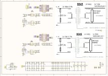
User Manual please see #55 and #108,DWG file of back panel please see #344.
DAM 1021 SK lite specification
1. MCU control DAM1021/1121 via isolate serial port. Real-time volume control, digital filter switching, input selection, PCM / DSD sample rate display.
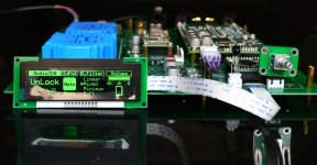
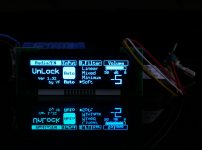
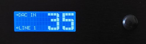
2. 3.1 inch OLED display(256 * 64 resolution).
3. One key mute (IRRemote only).
4. Rotary encoder or IRRemote will be control full function.
5. IR Remote control support learning function, support most kinds of IR Remote.
6. Power-down memory, automatically load the last shutdown settings.
7. With two different styles of display window, the screen display can be turned off
8. Using ISO7421 isolation chip between MCU and dam1021 / 1121, to ensure that MCU noise will not be introduced dam1021 / 1121.
9. There is a onboard transformer for power supply, AC 115V / 230V switchable. The output is completely isolated from the double winding, one power supply for the MCU and display part. The other power supply for the ISO7421 isolation chip, And provides 5V (400ma) and 3.3V (200ma) output, easy for the USB module and 1021 isolation chip for independent power supply.
11. Using high-quality solid capacitors, tantalum capacitors, ultra low noise ADP151, rotary encoder using ALPS EC11 type.
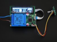
12. Display screen with FPC connector. While retaining the 2.54mm display interface(suppose SSD1322 256*64).
Attention: The transformer is included in the kits.
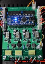
DAM 1021 SK specification
1. MCU control DAM1021 via isolate serial port. Real-time volume control, digital filter switching, input selection, PCM / DSD sample rate display.
2. 3.1 inch OLED display(256 * 64 resolution).
3. One key mute (IR Remote only).
4. Rotary encoder or IR Remote full function control.
5. IR Remote control support learning function, support most kinds of IR Remote 6. Power-down memory, automatically load the last shutdown settings.
7. With two different styles of display window, the screen display can be turned off
8. Using SI8642 isolation chip between MCU and dam1021, to ensure that MCU noise will not be introduced dam1021.
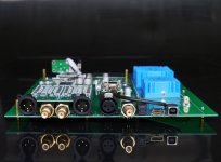
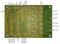
9. Input support: Optical fiber,Coaxial, AES, USB(not included), external I2S (LVDS mode).
10. RCA output can be switched between Buff and RAW.
11. Transformer board are detachable, support AC115V / 230V.
12. Use a separate winding transformer to power the USB module (amanero) and use ultra-low noise TPS7A47 for regulation.
13. Onboard TPS7A47 / TPS7A33 PSU.
14. A variety of DAM1021 power supply options.
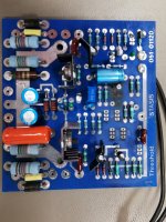
Attention: USB module (combo384), the transformers are not included in the kits. In order to be more compact, the official delivery of the PCB will be smaller than that of the photo, removing the extra edges
PCB size & OLED colour
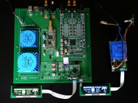
-AZ1021 SK : 220mm x240mm
PCB 2OZ copper and immersion gold
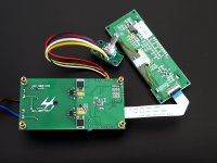
- AZ1021 SK lite: 50mm x 100mm
-OLED colour:Green, Orange or Blue.
The default is blue, please note the other colors.,There's only the blue OLED stock. If you need another color(green or yellow), you need an
extra $5 for the freight of purchase.
What is in the offer?
- AZ1021 SK: 169 USD , Not available
- AZ1021 SK lite: 99 USD , Not available
What do you get for the price
- AZ1021 SK lite: Finished board, what you see is what you get.
- AZ1021 SK: Finished board, USB module (combo384), the transformers, dam1021 are not included in the kits.
Shipping & fees, payment,Tax
ePacket (from China) shipping worldwide for free.If the ePacket does not support the area, need to pay an additional fee(ePackte, USPS FIRST CLASS MAIL INTERNATIONAL,Because of the delay of data exchange between China Post and USPS. It will take a few days for USPS to track the status.
You can also track on this site without delay. ALL-IN-ONE PACKAGE TRACKING | 17TRACK). Shipment is going to start in May 17th, once a week. I accept only PAYPAL, fees are included in the price.
Please PM your email to me and you'll receive an paypal invoice for what you are buying.
Exclusiveof tax;
Best Regards,
Audiozen


