So, I’ve cloned the Devore O96. Now I want try the Heretic Loudspeaker A612.
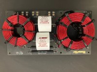
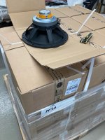
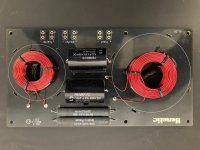
Here’s what we know. Outside cabinet dimensions are 30.25” x 25.5” x 17.75” and made from are 3/4” birch plywood. The co-axial driver is a Faital Pro 12HX230 based on a photo on HL’s Facebook page (attached). A photo of the crossover is also on their Facebook page (attached). According to the HL website, the driver is 8 ohms and the crossover is at 1700 Hz using a 2nd order Linkwitz-Riley series crossover. From the photo it looks like there is an L-pad on the tweeter.
Anyone care to take a crack at the crossover schematic?
Attachments

I wonder if they used textbook values-
OP/ manuf says 1700 hz, Impedance: WF8Ω/TW8Ω
Cross over picture shows 8.2 ufd cap and 10 ufd cap
see this chart 1500 and 2000 hz 8 ohm column
https://shop.koizumi-musen.com/?pid=145413356

You could scale out the parts for a guesstimate.
https://www.mundorf.com/audio/en/shop/Capacitors/Audio_Caps_EVO/
https://solen.ca/en/categories/inductors/products
OP/ manuf says 1700 hz, Impedance: WF8Ω/TW8Ω
Cross over picture shows 8.2 ufd cap and 10 ufd cap
see this chart 1500 and 2000 hz 8 ohm column
https://shop.koizumi-musen.com/?pid=145413356
You could scale out the parts for a guesstimate.
https://www.mundorf.com/audio/en/shop/Capacitors/Audio_Caps_EVO/
https://solen.ca/en/categories/inductors/products
Last edited:
I wonder if they used textbook values-
I doubt it.
This all i could quickly find other than places you can buy them. https://www.diyaudio.com/community/threads/12-coaxial-faital-pro-12hx230.314281/
A Zobel might allow for close to text book on the LP, but those 2 23Ω peaks right thru the XO reqion are gonna make a passive tricky.
Bi-amp might be the least painful. Digital would allow for the needed time delay usually required.
dave
Last edited:
You should start a new thread,
Faital Pro 12HX230 coaxial crossover needed.
--
Other options contact Faital Pro ask if they have a recommended crossover (with measurements). They should know.
Also vendors US Speaker, etc. They might recommend a generic 2 way crossover though.
--
Some form of electronic crossover, Behringer , miniDsp, etc
This looks interesting (there are other similar models in the Pioneer line up)
https://ampslab-spk.com/2016/10/13/pioneer-fh-x731bt-car-receiver-for-home/
If you can find a picture of the other side of the crossover board that would help.Anyone care to take a crack at the crossover schematic?
If the Heretic is really using a 12 dB/octave series crossover, keep in mind that the topology is different and pretty uncommon. Most books don't include equations to calculate them. The site below does, but I've only read it. I haven't tried to implement it.I wonder if they used textbook values-
OP/ manuf says 1700 hz, Impedance: WF8Ω/TW8Ω
Cross over picture shows 8.2 ufd cap and 10 ufd cap
see this chart 1500 and 2000 hz 8 ohm column
https://shop.koizumi-musen.com/?pid=145413356
The first order series crossovers I've attempted have also been a different beast when compared to more typical designs. They're harder to model/predict/massage response of than parallel crossovers.
https://www.tubecad.com/2017/11/blog0402.htm
"I have never seen the Linkwitz-Riley crossover alignment applied to the series crossover topology, so I had to roll my own. It wasn't hard.
"
Last edited:
oops-I missed the series crossover.
https://www.thehereticspeaker.com/ad612
say's, "Serial Linkwitz-Riley second order network
http://mh-audio.nl/Calculators/SLR2.asp
old info Andy Gradds Argos Loudspeakers (Australia), etc
https://web.archive.org/web/2003121...pg.com.au/users/gradds/series_cross-overs.htm
http://web.archive.org/web/20100528161050/http://members.optusnet.com.au/~gradds55/
https://web.archive.org/web/2003122...g.com.au/users/gradds/series_cross-oversK.htm
Acoustic Reality
http://web.archive.org/web/20040625235456/http://www.acoustic-reality.com/ar-sxo2.htm
Last edited:
It's really hard to say with any certainty without more data.
Obviously the raw tweeter level needs to come down. If both resistors are in series with the tweeter, and the crossover is similar to the one I posted above, that gets you something like 2.6 dB attenuation. That doesn't seem like enough given the factory frequency response curves, but i haven't heard the Heretic speaker or seen any measurements of it. Power dissipation in the resistors would be good to about 150 watts of input.
If the two resistors are in an L-pad configuration on the tweeter, that would be more like 7.5 dB attenuation. Since the values are atypical for an L-pad at this impedance, this configuration would also seriously interact with a series crossover, changing the roll-off of both drivers. Is this an incorrect assumption or exactly what they intended? I don't know. Power dissipation is much higher in the resistors in this configuration, but only at high frequencies, so I'm not sure it would be a concern. They'd still be fine to 100 watts of input up to 2.5 kHz, but dissipation increases pretty quickly above there.
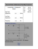
Funny- you have 10 uf & 8.2 uf known capacitors.Looks like they are using Butterworth. See attached.
Now, can anyone figure out the resistors and values? Are those in parallel or is it an L-Pad?
using this Series Calculator to find inductor values.
http://mh-audio.nl/Calculators/SLR2.asp
inputting various "Z" values & 1700 hz
Z 9.4 = 9.96 uf & .88 mH (close enough to 10 ufd) (orange impedence on graph right side 1700 hz Z value ?)
Z 11.4 = 8.21 uf & 1.07 mh ***(see the blue impedence at 1700 hz it looks @ 12 ohms)
Still unknown coil values.
Why would one copy completely unspecced and totally overpriced commercial designs? You can buy SOTA coaxial active Genelecs for that kind of money. Not copyable.
Go find a proven DIY coaxial design. You’ll save yourself a lot of uncertainty about getting the sound right. Just my 2ct.
Go find a proven DIY coaxial design. You’ll save yourself a lot of uncertainty about getting the sound right. Just my 2ct.
- Home
- Loudspeakers
- Multi-Way
- Heretic Loudspeaker A612 Clone