Threshold 4000 specs/info

I just love big, old power amps! And now I'm considering buying a model 4000 Threshold amp that is for sale. The look of this class A amp is fantastic, I can imagine the sound is too. But, there is very little information on the specs on this amp. My biggest concern is how well it can handle low impedance loads, since I will be using it on a pair Infinity Kappa 9.2i speakers.
Anyone here have some info on this amp?

ARTA Impulse Response

I'm trying to understand how to use ARTA to analyze impulse responses.

I have successfully recorded Impulse responses from external source into ARTA. When I look at them, they look ok and and I can then click the "FR" button to show a smoothed frequency response from that IR. All seemed ok.

Then I exported the IR as a wav, and imported it into REW and looked at the resulting frequency response in REW and the two programs don't match.

Not being sure what I'm doing or if I'm doing it right. I found an IR, actually one I use for my headphones as a correction. I imported that file into ARTA by being on the IR screen and doing a File/Import/.wav and selecting the file. I did the same thing in REW.

When I look at the two IR's on the screen, they look the same. Or at least as much as I can tell. Both go positive, then negative at around 48u, then back positive at .103ms, etc. By using the cursor the timing looks the same.

However, when I click the FR button on ARTA to get a frequency response and SPL/Phase button on REW, the two response curves are nothing alike. Furthermore, since I know that the FR of my headphones is suppose to look like, I know that the FR from ARTA is way off. I have attached files for the IR and the FR from both packages.

What am I doing wrong? How do I get ARTA to properly show me the FR from an IR?


IR from ARTA.JPGIR from REW.JPGFR from ARTA.JPGFR from REW.JPG


NOTE: The reason I'm doing this is I have an application where I need to record and IR from an external source (clapper). REW will not do that and since I own ARTA I'm trying to learn how to use ARTA to properly do that.

Maeshowe impressions

The Maeshowes with Pluvia 7.2 HD are playing. I had to taper down the bass by placing polyfill in the channels that are reachable from the outside. The other speakers are bass reflexes with Tangband W5-2143 and 3 notch filters (design Hobby Hifi, Germany). The Maeshowes project a fuller sound stage and play slightly louder. Apart from that the sound is similar. All in all I am pretty pleased with them.

Attachments

  • IMG_20220212_165952.jpg
    IMG_20220212_165952.jpg
    249.5 KB · Views: 244
  • IMG_20220128_211142.jpg
    IMG_20220128_211142.jpg
    643.2 KB · Views: 244

New to Hifi

Hello friendly enthusiasts,

I have built a Purifi 1ET6525 based stereo power amp, and bought myself a pair of KEF R3 Metas.

Now I need a signal to feed it, that will be good enough to get the most from my system.

Does anyone here know the Hypex preamp/dac/streamer modules? How good is it actually? If price is anything to go by (1995 eur), it should be pretty excellent and fully up to the task, but I know that’s not always the case. What would I be paying for the same quality as a finished consumer product? Are there better alternatives?

Thank you!

When would a subwoofer be a line source?

This question is spurred by my likely purchase of JBL CBT 70J-1 for listening at the far end of a very long room. To be paired with a subwoofer in the corner to fill in the low end. And also someone's thread of some stunningly lovely line source speakers made out of umpteen small drivers with like aluminum face plate.

Anyway, a line source in theory is making a wave expanding in a planar fashion instead of part-spherically, thus the SPL falling off as 1/distance instead of 1/distance^2. Usually you can't have a line source subwoofer because to get the planar effect the line length has to be more than or approaching or something the bass wavelength which is super long. OK, too bad, so sad. But suppose in my 8' ceiling American room, I stack 8x12" in the corner. Now the airflow is kind of "constrained" by the floor and ceiling so has to expand in a planar sort of way. YAY! There's my plane wave subwoofer to match by plane wave mains.

But there's trouble in Paradise! It's too big...what if I use only 7x12"? 6? 5? 4? At the long wavelengths it doesn't seem you'd need the subs literally touching, or that you could reduce from 16x6" (hard to get to go low) to 8x6" etc. How much space can you leave between? What if you put the woofers on different faces of the tall enclosure? What if you wrapped the vertical array with a kind of snail to make a huge vertical bass horn feeding planar into the room?

Really the low frequencies in a room are more complex in time and the 1/distance concept not applicable like at the higher frequencies but at least as a "wave launch" kind of idea I wonder when is a bass line source no longer a line source...

Dynaudio BM6 monitors crossover

I want to turn a pair of active BM6a into passive monitors, at least temporarily.

It's easy to just remove the back assembly with the amp, which leaves a connector that goes to both tweeter and woofer.

The BM6a (active) specs say the crossover point is at 2.2Khz, with the amp being 100W:
Dynaudio BM6A. User manual. English. Technical Specifications

Would I achieve good results using a cheap 2.2Khz crossover such as this one?

Or does it need anything special?

SHEVCHENKO Pure Tweeter Speaker Crossover 2.2KHz Treble Frequency Divider For 4 8 Ohm Home Audio Tweeter Unit 2pcs|Amplifier| - AliExpress

Here are the specs of the passive model:

Dynaudio Acoustics BM6 - 2-way passive monitor system

Back-EMF Motional Feedback / Amplifier Maximum Power Rating

Hi, everyone! Hope you're all doing fine.

I'm implementing a motional feedback system for a subwoofer which is based on recovering the driver's Back-EMF and feeding it back to the amplifier, so the driver's Qts can be effectively lowered. That would, theoretically, alllow me to obtain a flatter response, extending further towards the infrasonics, with a smaller enclosure.
The problem is: to stiffen up the suspension through electrical means, whilst maintaining peak SPL, I'll need to supply more power to the driver. That wouldn't be a problem per se, if I weren't already planning to run the driver at its average (or "RMS") power limits.

The question is: from your personal experience, how far can we push the peak power delivered to a subwoofer (given that we respect both its excursion as well as its average power limits) before it suffers mechanical damage from excessive motor force?

About the Driver
The driver is an 18WP600 from JBL. Its specs are as follows:
  • Fs: 35Hz;
  • Vas: 294L;
  • Qts: 0.46;
  • Qes: 0.48;
  • Qms: 20,4;
  • AES Power: 1200W [300W average (or "RMS")].
(https://www.parts-express.com/pedocs/specs/264-474--jbl-selenium-18wp600-spec-sheet.pdf)

About the Power Amplifier
The amplifier will be a custom Class-D power amplifier. Its relevant features are:
  • 8-Ohms output impedance;
  • PSRR-enhanced, fully feedforward architecture;
  • Average power capped by the PSU at 300W, peak power supplied by the bulk capacitors;
  • Peak power still to be determined. Crest factor is expected to be anything between 6dB and 10dB.

About the Motional Feedback
The new desired speaker parameters are:
  • 0.25 <= Qts <= 0.3.

The feedback will consist of (see picture attached):
  • Sensing the voltage across the driver, VSpk, as well as the current through it, ISpk;
  • Feeding a voltage representation of ISpk through a gyrated model of the RL network represented by the speaker's Re and Le to a transimpedance amplifier, obtaining a representation of the voltage across it, VReLe;
  • Subtracting VReLe from the scaled-down version of VSpk, obtaining a representation of the back-emf, VBEMF;
  • VBEMF is amplified and summed/subtracted to/from the signal fed to the power amplifier, according to increase/reduction in Q required.

Attachments

  • Back-EMF_Motional_Feedback.png
    Back-EMF_Motional_Feedback.png
    31.2 KB · Views: 87
  • Like
Reactions: Crashpc

Making high voltage umbilical aircraft inter-connects

After much trial and error, wasting materials, making mistakes, refinements, buying multiple versions of connectors, and many stupid mistakes... I've become somewhat of an expert at making high voltage umbilical connectors for separating a tube power supply from the amplifier. I wanted 10 conductors to cover many designs in the future. I also wanted to be able to send AC filament voltage across without inducting hum, so each cable has a twisted pair of 16 AWG that is shielded in a Belden-foil cable, this shield also has a 16 AWG drain wire which doubles to carry the safety ground from the PSU to the device, safety first. This leaves 7 more conductors. For the shorter cables (16 and 24 inch versions) I ran 20 AWG mil-spec silver teflon wires for these 7. For the longer cables (36 and 48 inches) these 7 conductors are 18 AWG silver teflon mil-spec wires. The designer can use these pins however they want. The designer can use a 36 or 48 inch cable to keep the "power brick" on the floor hidden. The shorter cable (16 inch) can be used when you want the PSU right next to or under the amp. The shield for the heater conductors (16 AWG) is dedicated as the safety ground transfer, and doubles to shield the AC heater from the other wires in the harness. Or you can run high-current DC filaments on these 16 AWG wires. The outer jacket of it all is made of 17mm OD 12mm ID latex laboratory tubing, very flexible, with high dielectric strength. The aircraft connectors themselves are rated to 500VAC / 700VDC but I would keep it under 500 because any wire also has to have a good rating. The connectors are 30mm diameter with 10 gold pins. I used a lot of high heat to solder the wire cups to make sure there were no cold joints, and heat-shrunk each solder cup inside the shell. Pulling the wire through the latex jackets, involves spraying some dry lube silicone on the wires, then using a fiberglass fish tape to pull the whole thing into the outer jacket. For the chassis connectors, you'd use the female connector on the PSU and the male on the amp, these attach with 4 screws in a 30mm hole, similar to how XLR connectors attach. I have some plastic hang-tags coming where I'll label the pins as to their wire gauge and if they are the shielded pair. I had to but a bunch of aircraft connectors to get the price break, so I'm on a roll making more of these than I'm likely to ever use. 10 conductors, but depending on the design an extra conductor can be had by finding the opportunity to share a ground, etc.

16 and 24 inch long cables pin configuration:

Pins 1 through 7 - 20 AWG silver/teflon mil spec (purpose as needed)
Pins 8 and 9 - 16 AWG Belfoil shielded twisted pair (typically for heater circuit) (high quality Belden cable used here)
Pin 10 - Shield drain wire (you must use this pin to carry the safety ground across so that both your chassis have a safety ground)

36 and 48 inch long cables pin configuration (thicker gauge is used here):

Pins 1 through 7 - 18 AWG silver/teflon mil spec (purpose as needed)
Pins 8 and 9 - 16 AWG Belfoil shielded twisted pair (typically for heater circuit) (high quality Belden cable used here)
Pin 10 - Shield drain wire (you must use this pin to carry the safety ground across so that both your chassis have a safety ground)

Voltage rating (using PTFE insulated wire)

Pins 1 through 7 - PTFE wire is rated 600VAC 840VDC, the connector itself is rated 500VAC 700VDC, therefore the whole cable is rated 700VDC if built as shown.
Pins 8 and 9 - The Belden cable used here is rated 300VAC 420VDC but is meant to be used for the low voltage heater.
Pin 10 - This is the safety ground, it should not be carrying any load


PXL_20241222_175352123.MP.jpg
PXL_20241222_175441441.jpg
PXL_20241222_175452613.jpg

Erm... I think I'm ready for a Cardigan

I'm 49 years old.
I don't (never used to) generally feel the cold, and I'm trying to save a bit of cash by turning the thermostat down in the house by a few degrees.
I'm generally ok, and despite it being 0 - 5 degrees (celcius) outside, it's not bad indoors.
I'm wearing joggers and a tee shirt. The stat is set at 18 degrees but I feel a little chill on my arms.
Am I ready to don a cardi?
I've never worn one before and I don't feel wearing a coat in the house is right..
Should I bite the bullet?
Any other cardi wearers here who can offer advice?

Hi from expat living in Taiwan

Great to meet you all.

I'm a head-fi obsessed enthusiast considering my first DIY project to build a headphone amplifier to power my favorite headphones these days - Modhouse Tungstens. These particular headphones are notoriously hard to drive being an oddity - low sensitivity, high impedance planars. Therefore, I first stumbled on this site attracted by the Elekit TU-8400 DIY kit capable of running KT170s, which has started to become a popular tube for driving this particular headphone.

I don't have much recent experience soldering so that's a concern but looks like Elekit's amplifiers are relatively newbie friendly.

Happy holidays everyone!

AD1862 PCB layout

I'm in the process of making an AD1862 dac board and would like some input on how to separate analog and digital grounds.

I want to make a single ground plane as Guido Tent recommends, and use proper positioning of the the components to avoid the digital cicuitry creating noise on the analog ground. This is very easy with the AD1865 and the PCM63 chips, as the digital and analog parts inside the chips are neatly separated along the middle. But with the AD1862 it's not so easy. Looking at the datasheet it seems like the lower left part of the chip is used for digital, and the rest is analog. So how do I position two chips next to each other without mixing the grounds?

The only way I've managed to solve this problem is to make separate mono dac boards. I've created the circuit on a prototype board. It works fine with a mono board. Very low noise. But with two dacs side by side on one board, the left channel gets really noisy.

Any input on this subject is very welcome.

Attachments

  • unnamed.png
    unnamed.png
    17.1 KB · Views: 2,371

Can someone give me tips on how to do a sine wave

I bought an arbitrary function generator, it will do a sine wave. I need this to set my adcom 5800 bias correctly. Can someone tell me exactly how to do this on this machine, according to adcom specs, I have it set on 1khz but I don’t understand the (Ampl) on the bottom what to set it at. Also when they say input, what is that referring to?

Attachments

  • IMG_1834.jpeg
    IMG_1834.jpeg
    123.2 KB · Views: 116
  • image.jpg
    image.jpg
    979.3 KB · Views: 117

Philips AD1255/M7 fullrange & AD5201s Bombardon enclosure help

Philips AD1255/M7full-range & AD5201s Bombardon enclosure help

Hello,

I'm wondering if any kind people can help me with making a decision on how best to utilise and to make a cabinet for these drivers. I'm fortunate in that I have 2 x near perfect AD1255/M7 full-range drivers and a total of 4 x (2 Perfect & 2 with marked cones) AD5201s/77 Bombardon Woofers.

I was planning on making each cabinet with 1x AD1255/M7 and 1x AD5201s/77. The plan was to use the Bombardon with the recommended crossover point of 800Hz and use the AD1255/M7 for the rest of the frequency range up to around 15KHz and then supplement the +15KHz with a Super-tweeter.

I have a DATs V3 and have measured all the driver parameters, I've also created WinISD driver files for all the drivers if anyone want to have a look at the driver parameters. Since the forum wouldn't allow me to upload the WDR file extension directly i've just added ".TXT" to the end of the file extension. The parameters can be viewed with Notepad as they are or if you want to add them to WinISD just delete the ".txt" part of the file extension to change it back to the WDR file type.


I'm also thinking that the largest enclosure I can get away with in the space I intend to use them would be in the 300 litre volume range.

Any help would be much appreciated.

Attachments

Fender Bassman TV 10 combo PSU failure

Dear all, my 2011 Bassman TV 10 is a great sounding little bad amp; unusual nowadays for having a 12AX7 valve preamp. Sadly it went quite a couple of months ago and I sent to the UK Fender Service Centre in Liverpool. They said that the PSU had failed and no parts are available anymore. The amp is effectively scrap. He did say that it was possible to replace/repair the PSU on the IC but they do not do that. Can anyone here help? Thank you for your time in reading this thread and I hope that everyone had a good Christmas.

Wandel & Goltermann analyzer, is it worth refurbishing?

I'm not sure was it Santa or Satan who brought me this for Xmass??
IMG_20241220_123829.jpg


It was sitting in humid and cold shed for years, but apart of few unimportant knobs and covers, it is complete. I left it in worm and dry to condition for some weeks before attempting to power up.

Half a century ago this was the top that money (a lot of it) could buy, but question is is this worth rebuilding today when REW and soundcards do all the job?
  • Like
Reactions: gerrittube

Rotel RMB1575 IcePower 500ASP and 500A fault finding

Experts,

I have a rotel rmb1575 which has 2 IcePower 500ASP and 3 500A modules. The amp is showing red protection on power up. I have the auto trigger off. I was troubleshooting and here are my notes. Initially I noticed that the surround speaker outputs were showing continuity. Others were not. Then I wiggled the inductor that was touching the terminals which seem to have insulated wires wound on a ferrite and then the short went away. This may indicate that there was a short which went away. I switched it on hoping that would be a fix but its not. How do I isolate if the issue is with modules or the rotel protection circuit or output boards. I also noticed that one of the 500ASP module showing a greed led on the board lit. The other board does not. Any troubleshooting steps to check and isololate. Thanks

Attachments

  • IMG_2783.jpeg
    IMG_2783.jpeg
    1.2 MB · Views: 95
  • IMG_2784.jpeg
    IMG_2784.jpeg
    1.1 MB · Views: 75
  • IMG_2785.jpeg
    IMG_2785.jpeg
    890.4 KB · Views: 81

What is the DIY speaker you consider “best” and why?

Hi,

I’ve a limited experience in building my own speakers, and by now the best speakers I’ve built are by far the Silbury with MA10.3.

What is the DIY speaker that you have built, designed or heard that is the best for you?

Please explain also why you consider it “best”.

I consider Silbury with MA10.3 superior to FHXL with MA11MS because of the detail and extension they have, but still the FHXL is a very very good speaker and extremely easy to build.

Thanks in advance to everyone.
Roberto
  • Like
Reactions: Audientid14

What is the current perception of the sound imprint of nickel coating + gold?

Hi all,

Well ... I have been working for some time now on a 6 layer DAC PCB that I am just about to send off for manufacturing (JLCPCB) - and then I notice that the only surface finish JLCPCB has available for 6 layer PCBs is an ENIG finish, which means a layering of nickel subsequently covered with gold.

And remembering that e.g. WBT (the German connector company) and others over time have been critical of nickel as a sublayer in e.g. connectors I was wondering if there is a current view on nickel's sound imprint?

Cheers & thanks for any insights on this 😉

Jesper
  • Like
Reactions: AIM65

Kind regards from Bavaria I like to building Speakers...

Hello,

Whenever I search for something about speakers I get this forum suggested.
So I registered today and am bringing you a few measurements.
I will soon be 50 but I have been building loudspeakers since I was 16. In the meantime I have made two PA systems and a dozen home hi-fi speakers.
I'm from Germany and have my own small woodworking section with a table saw and and.... I always build something different for myself privately, but mostly speakers ;-)
I don't claim to know much but I don't let up until I like it.
So sometimes mistakes creep in, small problem, I am honest and learn from it.
This forum seems to be very active when it comes to DIY.
I like that !!!

I try to deliver measurements, photos and my modest experiences from time to time.
In return I take advantage of your experiences 🙂

Best regards
Andreas

Power supply issue?

New here....having channel/power supply issues with amp and/or graphic EQ. Hoping to gain some knowledge and suggestions to correct the issues. I regularly loose left channel....if I partially unplug the EQ (Pioneer SQ-550) to a half-way loose-ish insertion I can regain stereo. First guess is bad power cord, but I'm no expert. Looking for other thoughts, recommendations and/or actions to take to correct the issue.

For Sale MFD. by Audio Development Transformer TF1A02LA A8691 365V -- NH USA --

Make offer in thread if interested.
I don't know anything about it.

MFD. by Audio Development Transformer TF1A02LA A8691 365V -- NH USA --

Attachments

  • 20241223_083531.jpg
    20241223_083531.jpg
    421 KB · Views: 73
  • 20241223_083854.jpg
    20241223_083854.jpg
    409.1 KB · Views: 66
  • 20241223_083857.jpg
    20241223_083857.jpg
    325.6 KB · Views: 54
  • 20241223_083901.jpg
    20241223_083901.jpg
    345.7 KB · Views: 45
  • 20241223_083906.jpg
    20241223_083906.jpg
    322.5 KB · Views: 47
  • 20241223_083911(0).jpg
    20241223_083911(0).jpg
    418.8 KB · Views: 49
  • 20241223_083911.jpg
    20241223_083911.jpg
    339.6 KB · Views: 55
  • 20241223_083914.jpg
    20241223_083914.jpg
    453.6 KB · Views: 56
  • 20241223_083916.jpg
    20241223_083916.jpg
    290.6 KB · Views: 70

Genuine NOS JFET FET K170 J74 K163 J44 K213 J76 K214 J77 and PCIe USB network clock PCBs

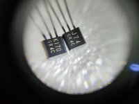
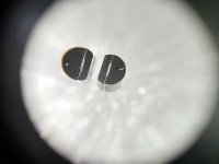
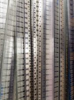
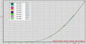
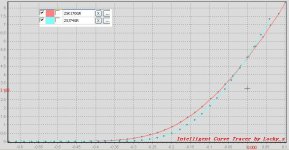
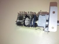
For sail. genuine components guaranteed, matched pairs are matched by a curve tracer. A lot of DIYers bought those componets from me years before.
2SK163 2SJ44 have better complementary characteristics than 2SK170 2SJ44.
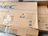
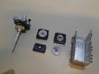
NOS JFET FET
Genuine Toshiba matched 2SK170GR 2SJ74GR pair(one pcs 2SK170GR and one pcs 2SJ74GR), 10$ per pair.
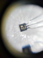
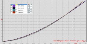
Genuine Toshiba matched 2SK170BL(two pcs 2SK170BL) pair, 8$ per pair.
Genuine Toshiba matched 2SJ74V(two pcs 2SJ74V) pair, 10$ per pair.
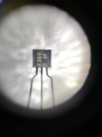
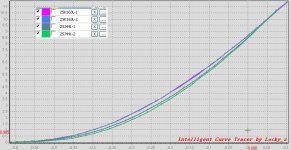
Genuine Toshiba matched 2SK369V(two pcs 2SK369V) pair, 10$ per pair.
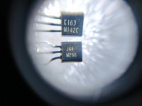
Genuine NEC matched 2SK163L 2SJ44L(one pcs 2SK163L and one pcs 2SJ44L) pair, 8$ per pair.
Genuine NEC matched 2SK163M 2SJ44M(one pcs 2SK163M and one pcs 2SJ44M) pair, 8$ per pair.
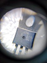
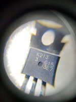
Genuine Renesas unmatched 2SK213 2SJ76(one pcs 2SK213 and one pcs 2SJ76) pair, 15$ per pair.
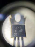
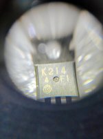
Genuine Hitachi unmatched 2SK214 2SJ77(one pcs 2SK214 and one pcs 2SJ77) pair, 15$ per pair.

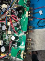
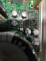
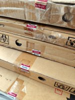
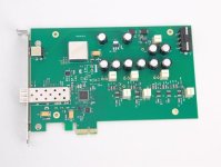
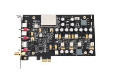
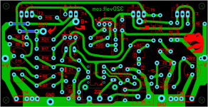
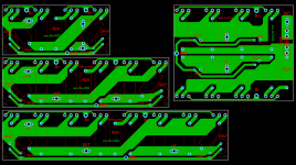
PCBs, all SMD componets are populated(except OCXOs and through-hole components and connectors),
PCIe USB Card : PCIe 1x, one USB 2.0 output, embedded sc-cut ocxo, external 10MHz input, external DC input, LT3045 regulator, ASM3142 chip. 300$ per pcs
PCIe Network Card : PCIe 1x, one gigabit SFP output, embedded sc-cut ocxo, external DC input, LT3045 regulator, WGI210 chip, 300$ per pcs
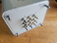
10MHz clock board: one sine wave output, 4 square wave output, LT3045 regulator, 300$ per pcs
Gigabit Network switch: two SFP ports, four RJ45 ports. embedded sc-cut ocxo, external 10MHz input, LT3045 regulator, 300$ per pcs
USB isolator: ground isolated, full USB 2.0 480MHz, one USB input , one USB output, embedded sc-cut ocxo, external 10MHz input, LT3045 regulator, 300$ per pcs
USB DDC: one USB 2.0 input, [OUTPUT, Spdif(DSD128 PCM384 max), AES(DSD128 PCM384 max), IIS(DSD1024, PCM1536 max), WORD CLOCK] embedded sc-cut ocxo, external 10MHz input, LT3045 regulator, 300$ per pcs

It will take 7 to 10 work days to arrange test and shipment. Shipped by registered airmail with tracking number or DHL or Fedex or EMS or equivalent.

Import duties, taxes, Paypal fee and charges are not included in the item price or shipping cost.

Attachments

  • IMG_20241204_142152.jpg
    IMG_20241204_142152.jpg
    344.2 KB · Views: 102
  • IMG_20241204_144040.jpg
    IMG_20241204_144040.jpg
    88.8 KB · Views: 83
  • IMG_20241204_144059.jpg
    IMG_20241204_144059.jpg
    74.7 KB · Views: 74
  • IMG_20241204_141442.jpg
    IMG_20241204_141442.jpg
    109.5 KB · Views: 76
  • IMG_20241204_143840.jpg
    IMG_20241204_143840.jpg
    158.5 KB · Views: 75
  • IMG_20241204_141044.jpg
    IMG_20241204_141044.jpg
    93.1 KB · Views: 83
  • IMG_20241204_140405.jpg
    IMG_20241204_140405.jpg
    215.3 KB · Views: 79
  • IMG_20241204_140411.jpg
    IMG_20241204_140411.jpg
    181.8 KB · Views: 74
  • IMG_20241204_142051.jpg
    IMG_20241204_142051.jpg
    392.7 KB · Views: 73
  • IMG_20241204_140734.jpg
    IMG_20241204_140734.jpg
    146.3 KB · Views: 73
  • IMG_20241204_140756.jpg
    IMG_20241204_140756.jpg
    155.4 KB · Views: 83
  • IMG_20241204_135648.jpg
    IMG_20241204_135648.jpg
    182.9 KB · Views: 61
  • IMG_20241204_140022.jpg
    IMG_20241204_140022.jpg
    87.8 KB · Views: 68
  • IMG_20241204_142228.jpg
    IMG_20241204_142228.jpg
    130.8 KB · Views: 68
  • 2SK163L2SJ44L.jpg
    2SK163L2SJ44L.jpg
    85.2 KB · Views: 71
  • 2SK163M2SJ44M.jpg
    2SK163M2SJ44M.jpg
    71.8 KB · Views: 66
  • 2SK170BL.jpg
    2SK170BL.jpg
    83.5 KB · Views: 69
  • 2SK170GR2SJ74GR.jpg
    2SK170GR2SJ74GR.jpg
    71.4 KB · Views: 78
  • PCIe-SFP.jpg
    PCIe-SFP.jpg
    28.8 KB · Views: 75
  • 20241210204843.jpg
    20241210204843.jpg
    41.5 KB · Views: 76

KEF Reference Model 3's cross-over component replacement

Hello gents,

I'm thinking of renewing the components of the SP2225 corss-over of my kef reference model 3's. I do have the schematic with the values. Replacing it with oem components is impossible so I need to source it somewhere. The speakers are working fine at the moment so the question arises...why would you replace it?...I wandering what kind of put-holes or pit-falls I might fall into and what to look for besides the obvious. I will measure the orginal ones first and compare them with the scheme below. any advise more then welcome....

happy new year...
1735290385348.png
  • Thank You
Reactions: GM

High power, high fidelity Class D amp with DSP+Bluetooth+Aux

Hello all,

After doing research on the web for a high power chip amp with built-in DSP and Bluetooth, we’ve realised that most products on the market had at least one major drawback.

Zoudio has a great product but the power is limited to 4x50W. The Beocreate 4 channel amplifier has limited power as well. The Wondom JAB5 has in theory all the features that you'd need but the sound quality is relatively poor.

We’ve therefore started to work on a new chip amp board that’s designed for the DIY market and we’d like to have your feedback. The board will have the following features:

- 4x200W @4Ω and 10% THD+N
- Typical THD+N of 0.01% (@ 1kHz, 70W, and 4 Ω)
- 4.0, 2.1, 2.0, and 0.1 configuration
- Built-in DSP using the ADAU1466
- Bluetooth 5.2 with aptX and the possibility to create stereo pairs (and more)
- AUX and I2S input
- ES9028Q2M SABRE Reference DAC
- LEDs, Buttons
- Possibility to connect a Raspberry Pi (for example to use as a streamer) or an Arduino

We’re considering making the board modular so that some of the components can be swapped for others, also considering the current chip shortage situation.

Pricing is still being worked on but we want to keep it as affordable as possible.

Soundstream LW4.500 Powers On but No Audio Output

Hi everyone,

I have a SOUNDSTREAM LW4.500 amplifier that powers on, is not in protection mode, and all voltages are present as they should be.

However, it doesn’t produce any sound output, and without a schematic, I can’t figure out the path the input signal takes.

Can anyone help me?

Thanks!

Giovanni

Attachments

  • IMG_20241105_180811.jpg
    IMG_20241105_180811.jpg
    742.3 KB · Views: 45

Hiraga 20W class A

I am an heretic and I am going to hell because I want to built a class A amp that is not a Pass project!
Having admitted to that, does anyone know anything about the Hiraga 20W class A amp? The somewhat incomplete schematic is posted in several sites so someone must have seen it and have some comments about it. It could be an interesting little project that distances itself from the usual crowd and that, most of all, does not involve buying mosfets, which I don't have.

3-Stage BJT Amplifier with Emitter Degeneration of VAS

I have a question, that must have a simple answer, but has been driving me crazy. I am simulating a basic 3-stage BJT amplifier, the circuit you will recognize from Bob Cordell's book on Designing audio Power Amplifiers. I have attached the schematic. When I simulate as a simple block diagram, everything works as I would expect. When I simulate the circuit, there is a dependence of the VAS current and emitter degeneration resistor (R5) that manifests itself as an offset in Vout. Seems like that offset should be driven to zero my the nature of the closed loop, but it does not seem to be the case? Any thoughts would be very appreciated.

50w-chapter-2.png

understanding star grounding

I would like to give you some impressions about star grounding.I hope the topic will help you avoid grounding issue.
1,star grounding is not problem with mono system,as a result it can avoid inner ground loops.surely it is not problem with dual mono stereo amp.
Ok then how about when the equipments are interconnected?
Notice,there are two way to make interconnector cables,connect the cable shield on both ends or connect the cable shield only at one end.whatever there are still no loops between the source and power amp.

Zang

Attachments

  • mono_interconnector.gif
    mono_interconnector.gif
    9.2 KB · Views: 24,602
  • Thank You
Reactions: Berlusconi

Help Measuring Ribbon Tweeter

As the title suggests, I have a couple of questions about measuring ribbon tweeters. My goal is to not blow up my measuring amp, destroy one of these tweeters, or get bad data.

Here is the ribbon in question: GRS RT1.R. These are back ordered and I have only two so I really do not want to break one.
https://www.parts-express.com/pedocs/specs/272-202-grs-rt1.R-8-spec-sheet.pdf

I have this capacitor I plan to use to measure it. 47uf
https://www.parts-express.com/Dayto...0V-Polypropylene-Capacitor-027-448?quantity=1

1. Will putting a single cap in series with the ribbon when I measure it throw it out 90 degrees out of phase? If so, how do I make up for that in VituixCAD?
2. I am assuming the 47 uf cap will cross so far below the range I plan to use it (4-5K and up) that it won't affect the measured frequency response where I plan to use it. Is this correct?
3. I can just use my regular impedance jig to measure this right? It is one of those diy 100 ohm jobs. I got it from A4eAudio (thanks again bud)

I plan to assemble this thing tomorrow and take measurements sometime this weekend. I will be posting a build thread with pictures once I get it assembled.

Attachments

  • Screenshot 2024-12-26 190825.png
    Screenshot 2024-12-26 190825.png
    392.8 KB · Views: 42
  • Screenshot 2024-12-26 190641.png
    Screenshot 2024-12-26 190641.png
    606 KB · Views: 49
  • Screenshot 2024-12-26 190628.png
    Screenshot 2024-12-26 190628.png
    782.9 KB · Views: 39

First ever sub build

I've been given some components that I want to use to build my home theatre sub.

  • Vifa M25W0-49
  • Whatmough 150W plate amp.
  • Sliding port
  • Sheet of 18mm thick ply, 900mm x 2050mm

I have various tools such as a jig saw, circular saw, drills etc and enough handyman skills to build things.

I want to build a sub box to place under my entertainment unit (400mm clearance). Possibly down-firing as I have kids with curious fingers.

I don't know where to start!

Attachments

  • IMG_5331.jpeg
    IMG_5331.jpeg
    548.4 KB · Views: 53
  • IMG_5330.jpeg
    IMG_5330.jpeg
    595.8 KB · Views: 54
  • IMG_5332.jpeg
    IMG_5332.jpeg
    344 KB · Views: 45
  • IMG_5341.jpeg
    IMG_5341.jpeg
    669.9 KB · Views: 47
  • IMG_5342.jpeg
    IMG_5342.jpeg
    361.2 KB · Views: 40
  • IMG_5401.jpeg
    IMG_5401.jpeg
    281 KB · Views: 40

The Well Tempered Master Clock - Group buy

Almost two years ago I started a thread to investigate the opportunity for a diyer to build a real low jitter oscillator.

Nowadays a couple of GB have already gone, but since it seems there is still enough interest, to keep the discussion tecnical only on the main thread, I decided to start a separate thread for the group buy.

You can find every technical detail and related discussion on the master thread at The Well Tempered Master Clock - Building a low phase noise/jitter crystal oscillator - diyAudio

Available parts, prices and Order Form in post #883
The Well Tempered Master Clock - Group buy

Quick guide for GB in post #805
The Well Tempered Master Clock - Group buy

Order summary
TWTMC_Summary of Orders - Google Sheets

DIY speaker design

Hi everyone,

I’ve been working on designing a custom speaker and could really use your thoughts and suggestions to improve it. I found a pair of Lii Song Silver 10 drivers at a low cost and decided to design a pair of speakers around those drivers. My goal is to build something unique with the following features:

1. A full-range driver mounted on an open baffle.
2. The ability to adjust the angle of the full-range driver to create an omnidirectional sound effect.
3. A sealed subwoofer to handle the low frequencies. I’ll be using 10 inch Dayton reference drivers for this.
4. A tweeter facing the front wall to enhance the soundstage.

For inspiration, I’ve looked at Decware’s ZROB (for the 40-degree angled open baffle) and Perry Marshall’s live edge dipole (for the rear-facing tweeter concept).

Here’s a rough idea of what the design looks like so far.

I’d love to hear your feedback—whether it’s design tweaks, suggestions for drivers, or even pointing out potential issues I might not have thought of.

Thanks in advance for your help!

Screenshot 2024-12-26 at 2.12.37 PM.jpeg
IMG_64C1A7C9F711-1.jpeg

Attachments

  • IMG_C3844AA6C097-1.jpeg
    IMG_C3844AA6C097-1.jpeg
    74 KB · Views: 33

Battery biased tubes

I am interested in designing preamp. With no feedback. The normal way is to decuple the cathode resistor with a cap. Thies cap tend to influence the sound and people tent to spend a lot of money for good quality ones. I was thinking if it would be an option to place a battery in the cathode instead, sines the internal is measured in milli ohms. This battery will of course be decupled as well. And I know that the voltages of the battery must be monitored and discharged in a proper manner over time.

I understand you need to find the right tube for a given battery voltage. Has anyone seen or have any experience with sus a setup?

STAR: Sziklai Transconductance Analytical Redux

Several suggestions were posted about my initial question about the Sziklai transconductance.
mirlo's suggestion: GMsz = Afet * GMbjt + GMfet in (#4 &) #6: -> What is Afet?
MarkJohnson has a 'datapoint' in #8: GMsz = 207.6mA/V -> How to calculate this datapoint?
knutn states in #9: GMsz = beta * GMfet -> how does the transconductance and the beta relate, just 'as is'?
steveu comes in #23 with: 16mA/V with a circuit where the Rsz is 10k, driving the J-fet next near to pinch off (the most distorting area).
knutn has a RIAA circuit in #24 that performs fine, the K170/556B prooves a good amplifier stage...
jsdyson wonders in #30 about the very low Id setting (40μA) with "well constrained distortion and useful freq response".

This last 'low Id' contraption is already found in the late 70's Sony TA-E86B preamplifier, it's odd 'bass boost' circuit intended for some audience.
The J-fet (Vdsmax= 12V!) runs at some 60μA without problems. I don't use that output actually.

The redux is about the assumption of a high beta, so the current through Rsz is determining the transconductance of the bjt (aka 'voltage driven' instead of 'current driven').
In this case the Sziklai-transconductance boils down to a simple equation, alongside the fet-bjt also valid for a bjt-bjt combo.
Nevertheless is knutn's remark in #9 and steveu's circuit with a 10k still in debate: what if there's no high beta and/or a very high Rsz, pressing the fet into performance jeopardy?
Comments & corrections are welcome.
(I use "S" for "GM"; S^ = Smax)

Attachments

  • TAE86E_BBcircuit.jpg
    TAE86E_BBcircuit.jpg
    60 KB · Views: 112
  • STAR.pdf
    STAR.pdf
    305.7 KB · Views: 74

Mogami W2490 Ultraflexible Miniature Microphone Cable (just pay shipping)

COMPLETED

Mogami W2490 Ultraflexible Miniature Microphone Cable. Two 40 feet bundles (minus a couple of feet that I have used). Cable was bought new from Markertek but unfortunately, it is too small (thin) for me to use. If you are interested, I can mail it within continental US if you just cover shipping.

cable1.jpg


cable2.jpg
  • Like
Reactions: pcjoe123 and Gill.T

XSA Labs TL Speaker

As you may have seen by now, there is a new TL speaker that I have been discussing in the other threads. It’s based on a combination of a couple of designs, the Vanguard for the baffle and driver placement and the PMC inspired foam core TL speaker. But modified with a different woofer and a new crossover for a completely new speaker that has a wonderful midrange and top end clarity combined with deep impactful bass. The crossover is my own unique passive Harsch for a quasi-transient perfect step response that gives excellent realism to percussion and strings and piano. Several prototypes are being built. You have seen one with black painted MDF and bamboo baffle.

1679053851082.jpeg


Now the all bamboo version is being built and it is looking great. Some progress photos.

1679053476996.png

1679053507244.png

1679053559426.png

1679053521957.jpeg

1679053654948.jpeg

Predicted F3 is about 48Hz but will depend on final stuffing / tuning and damping pads placement.
1679053728491.png

Active La Scala with allDSP Cross over and RiPol sub

Hallo everyone,
I‘ve been involved in diy speaker building some 10 years ago, finally struggeling with a LaScala clone activated with some self soldered quad405 amps - a friend did copies of print boards. An adventures, that didn’t come to a happy end. 10 years ago I bought the Adam Column active, which didn’t play as other expansive speakers didn’t too, because of the acoustic hell of modern architecture with several big resonaters like an open staircase and lots of large windows on 3 sides in house where I live. In won‘t tell anything about the stony way, which led to the miniDSP SHD and a pair of 15“ RiPol subwoofers, build with the kind support of Axel Ridthaler himself and driven by 600 W amp each. That was the match. Since that I‘m back in the business: some interests concern dipole speakers in combination with the Adam Audio Column to control the diffuse aspects of the soundfield, but the main project is a clone of LaScala in a two way version without the supertweeter but with a 18“ Ripol and DSP cross over with FIR Filters. The DSP board is from allDSP, a german company. That‘s all for the moment…..
Martin
  • Like
Reactions: grindstone

Heya! I am an audio enthusiast interested in building speakers.

Hello everyone!

I am an university from India who has a interest in audio equipment and its design, specifically it's engineering side. I have inherited this enthusiasm from my father who is also very much a enthusiast (building his first speaker when he was 17 !).

I keep seeing this forum everytime I am searching for specs for obscure drivers, crossover design advice and other audio stuff. So, I was already helped by this forum a lot and have decided to be a part of it. I would love to give the help back and also gain some knowledge.

My specific interest is building boxes for speakers. We have a lot of drivers in our home and I would love to turn them into proper speakers.

Once again, hello yall!
  • Like
Reactions: seventenths

Hello from Provins (France)

Hello from Provins in France, I am passionate about audio amplifiers and preamplifiers, particulary ARTEC french products that are no longer build and distribued today. Actually, i look for restore an old ARP300SE, an hi-end hybrid tube + MOSFET audio amplifier that sound very very well ! And a lot of others projects like, in a short time, the creation of a very high quality 12VDC/5A power supply to another audio application. First reasons that make i join your community today ! Best regards

Your first power amp build

Hi Everyone , It might be interesting to see what kind first projects have been built to enter into solid state amplification. I'll get it started with mine. Lab work with amplifiers in college never got past 5 watts. I remember the adjustable bench supplies as being 1.5 A at up to +/- 15 V. So, after graduation , I came across this Calectro / GC project in a 1980s hobby magazine. I built it with the horrid TIP series devices and all, but it worked. I got the DIY bug , days latter I bought the proper Mototrola devices ( MPSU , MJE , and MJ series power transistors) to rework the whole amp into a much upgraded 100 WPC amp. Once the front end was upgraded to a proper current source , I boxed it up into a nice chassis, along with a preamp from an op amp "cook book". I wound my own transformer with laminations salvaged from a TV transformer. Years later, I found out that the Calectro project was a knock off of a better , and more well known build from a 1970s magazine. Can anyone identify it ?

Attachments

  • ATS SCHEMO 1988.jpg
    ATS SCHEMO 1988.jpg
    304.4 KB · Views: 352
  • ATS BOARD 1988.jpg
    ATS BOARD 1988.jpg
    111.6 KB · Views: 326

2SA1302 / 2SC3281 replacement

I have a Sphinx Project 18 amplifier which is missing the output FETs.

Originally they are 2SA1302 / 2SC3281

Is there a good direct replacement (other than MJL1302/3281) for those available today? Where?

At first, I was planning to convert the amplifier for 2SJ201/2SK1530 but then decided to choose the easy way.

By the way, I used search and someone suggests using 2SA1943/2SC5200, but is that really a drop-in replacement? If so, which would sound better, this or MJL?

Oh, and the output stage design can be found on this doc on page 7 https://www.google.fi/url?sa=t&rct=j&q=&esrc=s&source=web&cd=7&cad=rja&uact=8&ved=0CFAQFjAG&url=http%3A%2F%2Fwww.transparentsound.com%2Fsphinx%2Fpj18designmanual.pdf&ei=K7B4U6SNNvT64QTb7YGABw&usg=AFQjCNGh4_r9FBhcS5ErWLg4EZJFZVFGHA&sig2=wVIyXG7iwo7ZS-f6DVFxBw&bvm=bv.66917471,d.bGE

Cheap accelerometer diy for speaker vibrations

After more research, I built a cheap piezo accelerometer, first to see how it works, the first tests with rew and arta. It's very simple to connect to the audio interface, I used it on focusrite solo 3rd generation, use bostik adhesive, blutack for gluing the piezo disc, it sticks perfectly to any material. To see if the vibrations disappear, use wooden vises (clamps) in the most vulnerable points, i.e. right next to the bass, where the biggest vibrations are produced, it must be reinforced there. Here are the connection pins:
DFR0052 Focusrite Solo
OUT --------> Pin 2 (Hot)
GND --------> Pin 1 (gnd)
Pin 3 (Cold) - optional gnd (Pin 1)

Attachments

  • 20181219phantom1.jpg
    20181219phantom1.jpg
    25.2 KB · Views: 127
  • IMG20241218125155.jpg
    IMG20241218125155.jpg
    338.7 KB · Views: 120
  • IMG20241218125808.jpg
    IMG20241218125808.jpg
    716.5 KB · Views: 108
  • IMG20241218125824.jpg
    IMG20241218125824.jpg
    623.5 KB · Views: 101
  • IMG20241218125905.jpg
    IMG20241218125905.jpg
    418.7 KB · Views: 102
  • REW V5.31.3 12_18_2024 1_07_31 PM.png
    REW V5.31.3 12_18_2024 1_07_31 PM.png
    353.5 KB · Views: 99
  • REW V5.31.3 12_18_2024 1_45_03 PM.png
    REW V5.31.3 12_18_2024 1_45_03 PM.png
    785.9 KB · Views: 96
  • REW V5.31.3 12_18_2024 1_45_11 PM.png
    REW V5.31.3 12_18_2024 1_45_11 PM.png
    844.1 KB · Views: 92
  • REW V5.31.3 12_18_2024 1_45_16 PM.png
    REW V5.31.3 12_18_2024 1_45_16 PM.png
    812.6 KB · Views: 86
  • REW V5.31.3 12_18_2024 1_45_40 PM.png
    REW V5.31.3 12_18_2024 1_45_40 PM.png
    337.9 KB · Views: 91
  • REW V5.31.3 12_18_2024 1_45_44 PM.png
    REW V5.31.3 12_18_2024 1_45_44 PM.png
    338.8 KB · Views: 78
  • REW V5.31.3 12_18_2024 1_45_49 PM.png
    REW V5.31.3 12_18_2024 1_45_49 PM.png
    329 KB · Views: 77
  • Untitled - Arta 12_18_2024 1_46_30 PM.png
    Untitled - Arta 12_18_2024 1_46_30 PM.png
    102.4 KB · Views: 79
  • VibrationSensorSKUDFR0052_pin.png
    VibrationSensorSKUDFR0052_pin.png
    32.7 KB · Views: 104

For Sale quad GZ34 NOS/NIB Philips (Mullard)

GZ34 Philips rectifier tube valves, made by Mullard UK in the early sixties, nice tube for amplifier projects. I have 3 pieces with the same code: F32 B3C4. One fourth tube has the code F32 B0K2.

Single ring getter, 7 ribbed plate side, red shining plate borders.

Tubes are NOS/NIB. I bought them more than 30 years ago in a shop and never used them.

Tubes will be packed safe with lot of soft materials.

Price 175 euro/pc; Shipping to Europe 20.00 euros, rest of the world please ask for shipping.

Attachments

  • IMGP3986_01.jpg
    IMGP3986_01.jpg
    307.3 KB · Views: 53
  • IMGP3985.jpg
    IMGP3985.jpg
    307 KB · Views: 50
  • IMGP3982.jpg
    IMGP3982.jpg
    369.6 KB · Views: 46
  • IMGP3981.jpg
    IMGP3981.jpg
    387.2 KB · Views: 52

This is likely a dumb newbish DAC question

Does the bottle neck of quality streaming and bit rate originate at the source….the DAC chip(s) in the original source(s)…. in my case a television and an old Blue Ray DVD player.

Suppose I’m a penny pinching Yorkshireman and enjoy the large display, seamless utility, and convenience of streaming music from my $80 Walmart 32” LCD TV in my office. The current set up has the TV’s optical output running to an Aiyima T10 preamp with a pedestrian DAC chipset. I do also use coax from an old blue ray DVD player into the Aiyima. I will rarely Bluetooth from my phone to the preamp. I never connect my computer to the preamp with usb as my computer has a slight ground loop and will introduce humming at times.

Is there any point of placing a better DAC between the TV and dvd player and the preamp (optical and coax to say an SMSL su1 then rca out to the Aiyima preamp input); or is this solely adding another potential source of distortion into the chain?

Alps Rotary Switch Dropout Issues for Input Select (e.g. Onkyo, Yamaha, Creek)

Alps Rotary Switch for Input Select for Onkyo (e. g. Integra A-9711/9911) and Creek (5350SE)
The main issue at this Alps input selector is the use of contact grease resp. contact liquid between the contact springs at the plastic device and the contact itself (see the images). For this reason it is impossible to remove the internal unwanted transition resistances with the help of any kind of contact cleaners e.g. like follow:
CRC WebSite: Maintenance and Repair products
KOC WebSite: Maintenance and Repair products
If it had not provided this lubrication at the contacts, I would use tuner 600 etc and success is provided.
This means, all kind of switches like the follow URLs must be disassembled.
http://bilder.hifi-forum.de/max/599916/sam0273o_69807.jpg
Onkyo A-9711 - Welche Funktionen fernbedienbar?, Verstärker/Receiver - HIFI-FORUM
http://images.gutefrage.net/media/f...911-aus-eingangswahlschalter-defekt/0_big.jpg
Wer kennt sich mit ONKYO- integra Vollverstärker A-9911 aus? Eingangswahlschalter defekt! (onkyo-integra-a-9911)
Onkyo A-8051 und kranke Schalter von ALPS
View image: 20130429 151559
View image: 20130429 151526
The attached images are from me.
Clearly to see are the contacts before and after cleaning. After assembly the rotary switch and resold on the PCB the user get a kind of operating while the input select like new condition, i. e. without any dropouts at one of the channels.
It is particularly difficult (very hard) to desolder the rotary switch in such cases, where the solder pins were bent before soldering.
In case of breaking the solder pins silver wires must be soldered. That means the risc of alter the correct installation position.

Attachments

  • CAM00724.jpg
    CAM00724.jpg
    555.7 KB · Views: 3,743
  • CAM00726.jpg
    CAM00726.jpg
    533.4 KB · Views: 2,813
  • CAM00728.jpg
    CAM00728.jpg
    348.4 KB · Views: 2,445
  • CAM00730.jpg
    CAM00730.jpg
    417 KB · Views: 2,683
  • CAM00735.jpg
    CAM00735.jpg
    491.5 KB · Views: 3,696
  • CAM00741.jpg
    CAM00741.jpg
    646.2 KB · Views: 1,904
  • CAM00742.jpg
    CAM00742.jpg
    574.1 KB · Views: 2,029

Coaxial Speaker Build - Crossover advice needed

Hello,

I am building a coaxial speaker with the following drivers:

Eminence Beta 12CX
PRV Audio D290Py-S

I built large cabinets with the following specs:

Vb - 3.67
Fb - 37.8Hz
F3 - 43.6
Ports - 2
Port diameter - 4"
Port length - 11'

IMG_3746.jpg


For the crossover I used the following thread on this site to get started: https://www.diyaudio.com/community/...igning-crossovers-without-measurement.189847/

I used a 1000Hz crossover point. Based on the calculations I ended up with the following crossover (at this point I hadn't reversed the tweeter polarity as shown):

Original crossover.png


At this point I built my cabs and crossover, not knowing how to use xsim yet. I also used a L-pad knob to bring the tweeter level down, as there is a 12db difference in sensitivity. In general I LOVE these speakers, the horn driver especially sounds incredible...highly recommend... but due to a room mode I started making speaker measurements using HouseCurve and noticed a big dip at the 2000Hz region, to which I reversed the tweeter's polarity and got much better results. However I now get a large db bump from the 500-2000Hz region. I turned the tweeter knob down all the way which still left a 500Hz spike so that got me thinking its not just the tweeter level. I eq'd it flat and it now sounds incredible...but I would really like to get the crossover dialed in so I started poking around with xsim and finally got the basics down. I created measurement files for both drivers and got the following freq response which seems to line up with the problem I am facing:

original freq response.png


As you can see my levels start to peak before my crossover point....so I started playing with my crossover. I ended up zeroing in on lowering the parallel resistor on the tweeter to 1ohm and it seems to be the kind of response I am looking for. Is this going to work? The driver responses look way off but the series curve (blue line) looks linear and nice...am I doing this right?

new crossover.png


new freq response.png


Thank you for any feedback 🙂
  • Like
Reactions: Audio>X

Pioneer PD-206 not spinning

So I found my old Pioneer PD-206. I put in a CD and with a little help closing the tray (as the belt is stretched, ...nothing happened

I entered service mode and checked that the laser was firing, and the motor was spinning.

Then, I sprayed some contact cleaner on all trim pots and moved them end to end, and re-set them to their original position. After this it started doing "something".

I got the manual and started the calibration procedure. I fudged with the RF level pot and the focus gain until I was able to track focus (i think): the CD started spinning clockwise and i could hear the focusing. Scoping the test point showed me some waveforms close to what the manual says.

But when I turn the unit off and on, it tries reading the disc and "crashes": it won't turn off, or respond to anything.

I don't remember if this player was already not working when I put it away (in the early 2000s I was using a Sony player after this Pioneer). So i'm not sure if it could be a bad pick up unit (new ones are out of the question - $150 each, and a new player costs less).

Any ideas?

Edit: now that I think about it, this wasn't MY old cd player. I must have got this one for free at some point. My old CD player was a pioneer too, but it was a dual deck. So maybe this one is just dead. Again i'm not sure if it could be a bad pick-up or something else. Do these pick ups fail as often as late 90s pick ups? I remember, at my dad's shop we changed hundreds of KSS-213s. these failed a lot.

DML system 1.0

Here's the first revision. Note, this project did NOT start as a DML project. That came up unexpectedly looking at speaker options for a tough space. I haven't had a home audio system beyond headphones since 2006 (due to family, as a bachelor, I had a killer home theater). I have space constraints -- the boxes are workable because they weigh nothing and I can hang them up elsewhere when not using. Here's the first round:

system1-0a.jpg


40 watts and it sounds pretty incredible at desk listening distance. Speakers are the 6$ exciters. The sub is the Goldwood 406D which is now 15$. I didn't mount the plate to it as I've heard some people have trouble with a good seal and also want the option to upgrade. Back can be opened to upgrade the woofer at some point also. It's reclaimed 3/4" hard maple. I didn't even know about these tiny amps. I recycled a great vintage Yamaha because I just don't have room plus the weight. If I knew about these little amps you can get, I might have started this project a few years ago. The aesthetics of this setup is the biggest issue. I had issues with my 1/4" round bit which I think would look better for the woofer and also it could use a couple padauk pinstripe inlays. The box on right should be unfolded to match the print of the box on the left.

So, version 1.1? I got the DAEX32 EP4 exciter, 40w, and mounted the first one to the typical pink insulation square; rounded corners, sanded. Haven't listened to it since gluing it on. In the press-against tests they sounded better with the squares than the cardboard towers; to me the little ones were better with cardboard. I'll get to a proper test in the next couple of days. Turns out I have a space on one wall I can make these work, I think. Not ideal listening position but...

I haven't thought about audio in so long I've forgotten just about everything. I have 2 studio monitors with 6.5" drivers -- they are heavy as sin and no way for me to use them in the space I have. However, they can be wired "bi-amp" so I should have tried using one of those as a sub before building one. If good, then I do have space on the floor and I can have 3 of these smaller subs (no room for my 10" Energy sub in storage). For just my desk area, the sub I made is all I'll ever need. In fact, on my second day of listening I kept turning it down. However, my imagination is on a binge and if I can put them away easily, then I have a recliner that faces a TV that you can see on the wall, and setting something up between the TV and the recliner so I can listen there, or even for a makeshift HT would be cool.

I did have a question: what do people think about these:

https://www.parts-express.com/GRS-PT6816-8-8-Planar-Slim-Tweeter-8-Ohm-272-128?quantity=1

I'm not bound to DML. I just thought it was a cool / cheap idea to experiment and it's lightweight stuff that I can manage in my space.

Doesn't have to be this brand, but would planer tweeters like this sound good from 2.5' away? would they be too much? I could try something like this for the build for the listening chair but wondering about mid-range; in addition to having subs, what else would you need to support these?

Vintage board UAP-02 - RCA 70 Watts - Temperature problems

This is a request for help to the older ones here ( me too 😉 ) twho surely knew the RCA power amp based on the UAP-02 board. I'm talking about the 70's. I built the 70 Watt version of this amplifier back then, and every now and then I used it, normally I used it with my PC to feed two small speakers, so it was never used intensively or at high volumes. But, (there's always a first time) lately the left channel started to heat up so I decided to put the noble NAD 3020 in its place, and decided to see what was causing the overheating. I proceeded to check DC voltages at the output (Offset), 1.0 mV on the left channel and 9.0 mV on the right, which I considered acceptable, so the next step was to check the quiescent currents (Bias). As it was recommended in the days of analog multimeters, I did not use the typical procedure of inserting the ammeter in the collector junction of the output TRs with the + B, because the internal impedance of the same would slightly alter the measurement and this method forces us from physically opening the circuit. (Although I remember having done it on DIY - Phillips boards without problems - I do not know if using a digital multimeter the same thing happens) Applying Ohm's Law, in theory the Bias of the left channel was 41.5 mA, and of the right channel 45.9 mA, which caught my attention, I expected that the one that exceeded the maximum recommended by RCA (40 mA) was the channel that was heating up, the left one, but it is the other way around.
That said, I proceeded to adjust the presets of both channels. (RCA recommended installing a 100 Ohm preset instead of R11 in case of temperature problems.) and I managed to adjust both channels as you can see:
+B 39.5 Volts DC / 117.5 Ohms = 33.6 mA.
I was surprised that the preset allowed me to exceed the maximum 100 Ohms, but I suppose that the manufacturing tolerances in those years were quite large.
But, I was greatly surprised to find that after these adjustments, BOTH channels overheated much more, evenly and gradually, and in a few minutes!
With an ambient temperature of 27 ° C, in 10 minutes the heat sinks reached 45 ° C! The amplifier works well, and the offset now, with this temperature, is 8 mV on the right channel and 0.7 mV on the left channel.....At this point, I turn off the amplifier, the 40636 output from RCA indicates maximum 200 °C, but I won't wait to spoil them, this operation is not normal...
I really can't figure out why this can happen, I thought that some TR - input differential pair - could have become unbalanced, which usually causes anomalies in the DC output, but, that failure in both channels simultaneously? And also the DC at the speaker output is not so high...
Should I go back to the traditional Bias adjustment?
What have I forgotten in all these years ?
I will appreciate any thoughts that help !

PS: The diagrams are taken from the web, the notes and measurements do not correspond to my amplifier. I will look for the original diagram and upload it, although being in red I fear that it is not very visible.

Attachments

  • 2-bb163c3178.webp
    2-bb163c3178.webp
    96.5 KB · Views: 124
  • Instalación fuente y Led - Potencia RCA 007.jpg
    Instalación fuente y Led - Potencia RCA 007.jpg
    96.6 KB · Views: 88
  • Instalación fuente y Led - Potencia RCA 032.jpg
    Instalación fuente y Led - Potencia RCA 032.jpg
    108.3 KB · Views: 90
  • Instalación fuente y Led - Potencia RCA 037.jpg
    Instalación fuente y Led - Potencia RCA 037.jpg
    107.9 KB · Views: 91
  • Potencia RCA 031.jpg
    Potencia RCA 031.jpg
    68.8 KB · Views: 96
  • Instalación fuente y Led - Potencia RCA 017.jpg
    Instalación fuente y Led - Potencia RCA 017.jpg
    135.7 KB · Views: 112
  • amp6.jpg
    amp6.jpg
    91.3 KB · Views: 130
  • circuito.jpg
    circuito.jpg
    479.6 KB · Views: 128

Conrad Johnson PV10A voltages

So I gave Conrad Johnson a call in regards to the voltages at certain points in the schematic. They don't offer these on the schematic because they do in-house servicing for customers. However at $150 an hour my PV10A is never going to get there especially because I fix all my own stuff.

My system has an over voltage issue which results in the NPN transistor in the primary power supply shorting collector to emitter. They read somewhere in the neighborhood of 360 volts.

I was hoping if somebody here has a PV-10A, with phono stage, if they could perhaps probe a couple points for me and let me know what their voltage is are. Mainly what I really need is what is the voltage on each of the large 20 UF bulk capacitor after the bridge rectifier.

Also I was hoping that somebody was able to get some voltages for me to find out what the AC output of the transformer is on the high voltage and low voltage test points.

If someone is able to crack theirs open I could take a picture of mine and point to a few other places where I need voltages.

All the components seem, And that is a heavy seem to be spot on. I double checked the transformer primary wiring to make sure I wasn't somehow producing higher secondary voltage.

The smaller filament supply seems to be working perfectly.


I am a newbie in this forum so be gentle.

Thanks for your time if you made it this far!

Dear Sirs/Madams! I salute you

Greatings all!
My name is Jørgen, born and bread in Oslo Norway, pushing 60 and not really a freshman on this glorious site.
However this is my first hello as up to now i have only been present as a bottomfeeder, feasting on your accumulated knowledge to improve my skills and verify the validity of my own projects.
So here i am and ive got a question i am eager to post in the apropriate department.
  • Like
Reactions: grindstone

3116D2 amp and some questions

I just finished my very first amplifier, with schematics based on tpa3116d2 evaluation module (https://www.ti.com/lit/ug/slou336b/slou336b.pdf). The only change I made was to drop the gain to 20dB, and remove some jumpers. I threw together the box from 0.25" oak board pieces. All parts came from digikey, except the power button and connectors that I ordered on aliexpress. The PCB was designed in kicad and manufactured by jlcpcb. This was a very exciting project overall (for me). I still have a few remaining problems and would appreciate some help,

(1) The speakers emit some white noise when there is no input. It is barely audible, but becomes about twice as loud a few seconds after the input stops. Does anyone have an idea on what could be going on? In any case, I can still only hear it if I put my ear next to the speakers.

(2) I would like to have two stereo inputs in it. I was planning to add a mixer. Could someone please suggest a mixer that is decent and not too complicated to understand? I don't have enough experience in audio to design something like that. I did go over the mixer page (https://sound-au.com/articles/audio-mixing.htm) and some opamp theory in Sedra's book.

Thanks All.

Attachments

  • image.jpg
    image.jpg
    798.4 KB · Views: 69
Projects by fanatics, for fanatics
Get answers and advice for everyone wanting to learn the art of audio.
Join the Community
507,529
Members
7,875,696
Messages

Filter

Forum Statistics

Threads
405,667
Messages
7,875,696
Members
507,529
Latest member
jmanoo