As the title suggests, I have a couple of questions about measuring ribbon tweeters. My goal is to not blow up my measuring amp, destroy one of these tweeters, or get bad data.
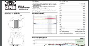
Here is the ribbon in question: GRS RT1.R. These are back ordered and I have only two so I really do not want to break one.
https://www.parts-express.com/pedocs/specs/272-202-grs-rt1.R-8-spec-sheet.pdf
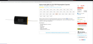
I have this capacitor I plan to use to measure it. 47uf
https://www.parts-express.com/Dayto...0V-Polypropylene-Capacitor-027-448?quantity=1
1. Will putting a single cap in series with the ribbon when I measure it throw it out 90 degrees out of phase? If so, how do I make up for that in VituixCAD?
2. I am assuming the 47 uf cap will cross so far below the range I plan to use it (4-5K and up) that it won't affect the measured frequency response where I plan to use it. Is this correct?
3. I can just use my regular impedance jig to measure this right? It is one of those diy 100 ohm jobs. I got it from A4eAudio (thanks again bud)
I plan to assemble this thing tomorrow and take measurements sometime this weekend. I will be posting a build thread with pictures once I get it assembled.
Here is the ribbon in question: GRS RT1.R. These are back ordered and I have only two so I really do not want to break one.
https://www.parts-express.com/pedocs/specs/272-202-grs-rt1.R-8-spec-sheet.pdf
I have this capacitor I plan to use to measure it. 47uf
https://www.parts-express.com/Dayto...0V-Polypropylene-Capacitor-027-448?quantity=1
1. Will putting a single cap in series with the ribbon when I measure it throw it out 90 degrees out of phase? If so, how do I make up for that in VituixCAD?
2. I am assuming the 47 uf cap will cross so far below the range I plan to use it (4-5K and up) that it won't affect the measured frequency response where I plan to use it. Is this correct?
3. I can just use my regular impedance jig to measure this right? It is one of those diy 100 ohm jobs. I got it from A4eAudio (thanks again bud)
I plan to assemble this thing tomorrow and take measurements sometime this weekend. I will be posting a build thread with pictures once I get it assembled.
Attachments
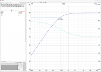
The filtering effect of adding a single capacitor in series with the ribbon tweeter can be simulated in VituixCAD. The ribbon tweeter has a relatively constant resistance, which sits at around 8 ohms. This behaviour is included in the driver used in the circuit shown below.

The 47μF series capacitor has introduced a first-order high-pass filter response function. The electrical response is –3dB at about 426Hz, where there is an additional 45° of phase shift. By 1kHz, the attenuation is only 0.8dB or so, with a phase shift of 23°. The phase response curve indicates that the full 90° of phase shift only happens once the frequency drops below 20Hz.
The 47μF series capacitor has introduced a first-order high-pass filter response function. The electrical response is –3dB at about 426Hz, where there is an additional 45° of phase shift. By 1kHz, the attenuation is only 0.8dB or so, with a phase shift of 23°. The phase response curve indicates that the full 90° of phase shift only happens once the frequency drops below 20Hz.