I would like to give you some impressions about star grounding.I hope the topic will help you avoid grounding issue.
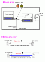
1,star grounding is not problem with mono system,as a result it can avoid inner ground loops.surely it is not problem with dual mono stereo amp.
Ok then how about when the equipments are interconnected?
Notice,there are two way to make interconnector cables,connect the cable shield on both ends or connect the cable shield only at one end.whatever there are still no loops between the source and power amp.
Zang
Attachments
Interesting. I am currently fighting this ground hum. If I put a pair of amp (L+R) no hum. But once I put additional pair (to make it 4-channel) I hear hum.
At the end I had "all grounds connected everywhere" to obtain minimal hum - still audible on very quiet night.
What is the correct grounding for stereo amps then ?
At the end I had "all grounds connected everywhere" to obtain minimal hum - still audible on very quiet night.
What is the correct grounding for stereo amps then ?
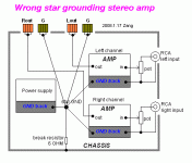
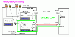
continue the case 2,
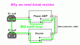
when the equipments are interconnected,whatever what kinds of the cable shield way you are using.there a big loop between the source and power stage.the interconnector is a pair of antenna
this can explain why you amp is quiet but when connected the source,the hum coming.
when the equipments are interconnected,whatever what kinds of the cable shield way you are using.there a big loop between the source and power stage.the interconnector is a pair of antenna

this can explain why you amp is quiet but when connected the source,the hum coming.
Attachments
to prevent ground loops,i do works below:
connect all signal grounds (RCA plate terminal) to one common point,
choice one power unit's ground as common ground.the common may be a wire,a track on a pcb,
assemblied the power units as compact as possible.
P.S.
when do air wring,use strong wire or big copper as common ground.
when you design a pcb board,you have to be smart address the specific factual situations of grounding.lay out enough grounding pads on your board.
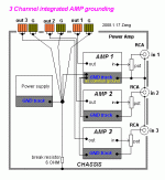
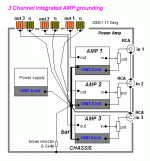
to design a circuit board for integrated amp,layout multi-channel amp in one board with star ground concept.
star ground is talk about pcb layout technology.star grounding is talk about wire connecting technology.do not mix up.
the attached is a example of grounding 3 channel amp in a single chassis.
Zang
Attachments
the attached is another idea.
it is useful when you build an integrated amp with pieces single channel pcbs.
connecting all pcb's ground track via a strong wire.i use 4mm diameter copper wire.this wire is your amp's common ground.then connecting all RCA plate together to this common ground.
again,
assemblied the amp units as compact as possible.
Zang
Attachments
Thank you....thank you... 🙂
I think one of my mistake is not isolating the input RCA grounds. They are connected to the chassis!
I think one of my mistake is not isolating the input RCA grounds. They are connected to the chassis!
you are welcome🙂
because when the equipments are interconnected,there are big earth loop caused by the common earth terminal on the wall IEC socket.
the 6 OHM is not a regular value.and the break resistor is not the only way.it is just simple.
Zang
Paswa said:Why need the break resistor of 6 ohm??
because when the equipments are interconnected,there are big earth loop caused by the common earth terminal on the wall IEC socket.
the 6 OHM is not a regular value.and the break resistor is not the only way.it is just simple.
Zang
Attachments
gainphile said:Thank you....thank you... 🙂
I think one of my mistake is not isolating the input RCA grounds. They are connected to the chassis!
I Had problems finding a isolated panel mount rca connector for my projects , But this really is a very most important thing.
I built a 5 channel surround amp with each channel in its own enclosure and one enclosure for my powersupply , so basically i have a small star ground in each of the 5 amplifier enclosures. Luckily i have now hum.
tang
Hi,
I prefer the post7 grounding layout as it gives more consistently low hum compared to post5 for two channel amplifiers.
I also find that when using multichannel amplifiers that separating the PSU grounds helps as well. This requires the use of dual rectifiers for each PSU and then connecting the zero volt line from the smoothing caps to the star ground.
Finally, there is a safety issue that has been overlooked with the layouts posted.
The 6ohm disconnecting resistor between Safety Earth (chassis) and Audio Ground (Star Ground) does not comply with the mains safety requirement of most countries.
The exposed conductive parts must be permanently connected to the Safety Earth.
The reason for this requirement is to ensure that the mains fuse blows quickly, if the mains live lead during a fault condition contacts and/or connects to other low voltage parts of the equipment.
If fault current prior to the fuse blowing passes from Live to Audio ground then through the 6ohm resistor to Safety Ground back to distribution board earth the voltage appearing on the audio ground will be high enough to kill anyone that happened to touch the equipment at the wrong time. Further, fault current passing through the resistor will more likely blow the resistor before it blows the fuse, leaving the Audio ground at Live voltage and no effective connection to Safety Earth.
I recommend either of two solutions.
The first and safest is direct connection from Safety Earth to Audio Ground. This generally gives rise to hum loops in most connected equipment.
The alternative is to use a Disconnecting Network between Audio Ground and Safety Earth. This Disconnecting Network can consist of a parallel combination of:- Power resistor, inverse parallel coupled Power diodes, Power Thermistor, HF capacitor.
The Disconnecting Network MUST survive LONGER than it takes the mains fuse to rupture and for the arc to extinguish.
digi01 said:the attached is another idea.
it is useful when you build an integrated amp with pieces single channel pcbs.
connecting all pcb's ground track via a strong wire.i use 4mm diameter copper wire.this wire is your amp's common ground.then connecting all RCA plate together to this common ground.
again,
assemblied the amp units as compact as possible.
Zang
If this grounding scheme is used, but the power supply is in a separate chassis (6 foot cable between the two), should the break resistor be put in the amplifier or power supply chassis?
As Andrew T has stated, never put resistance onto your safety earth.
Under fault condition there will be :-
a) high AC voltage on any exposed metalwork (OUCH!)
b)your protective devices will not operate properly in the specified
time (double OUCH!!)
Under fault condition there will be :-
a) high AC voltage on any exposed metalwork (OUCH!)
b)your protective devices will not operate properly in the specified
time (double OUCH!!)
gareth said:As Andrew T has stated, never put resistance onto your safety earth.
Under fault condition there will be :-
a) high AC voltage on any exposed metalwork (OUCH!)
b)your protective devices will not operate properly in the specified
time (double OUCH!!)
I would also be paralleling a capacitor/bridge rectifier to create the "disconnect network" instead of just a resistor
fluckscapacitor said:
I would also be paralleling a capacitor/bridge rectifier to create the "disconnect network" instead of just a resistor
What would you like to know in regards to this?
Gareth
Thanks Digi01
Images posted here by Digi01 are excellent !!
What the (DIYaudio) world needs now is -
a translater/image maker who will -
translate AndrewT's "two solutions" in post 13
into an image as clear and easy to understand
as those posted by Digi01
Images posted here by Digi01 are excellent !!
What the (DIYaudio) world needs now is -
a translater/image maker who will -
translate AndrewT's "two solutions" in post 13
into an image as clear and easy to understand
as those posted by Digi01
gareth said:
What would you like to know in regards to this?
Gareth
The appropriate way to do star grounding (which may or may not include the disconnect network) with a stereo amplifier that has a power supply in a separate chassis and a long cable between them
fluckscapacitor said:
The appropriate way to do star grounding (which may or may not include the disconnect network) with a stereo amplifier that has a power supply in a separate chassis and a long cable between them
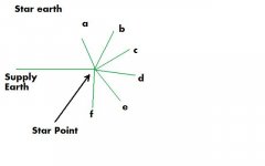
Perhaps this will help. Also pay attention to where your equipment is supplied from. I do not connect mine from different outlets and I also use a radial supply and I have never had any ground hum loops.
Gareth
PS..I think I should state again that you should not put any sort of resistance on your supply earth, you will be asking for trouble under fault conditions. Apply ohms law with some figures and see what you come up with to support this
Attachments
- Home
- Amplifiers
- Power Supplies
- understanding star grounding
