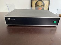
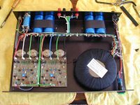
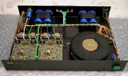
Building the ultimate NOS DAC using TDA1541A

Hi,

I just joined diyAudio.com. I have spend my entire life designing, repairing and buildingjavascript:smilie(':smash:') electronic equipment, electronics is my passion. I have designed a lot of High-End audio equipment over the last decades. The following projects are the "newest":

-Fully symmetrical cascode MOSFET amplifier with high resolution microcontroller based VU meters.
-Modular 6 channel control amplifier with remote control
-Modular input switchbox
-Twin TDA1541A DAC in differential mode with 8th order active hybrid filter
-Sonic resonators (passive semi 4-way 360 degree omnidirectional radiators
with real-time error correction). How do they sound? hearing is believing!
-Non inductive copper wire resistors for High-End passive filters, using stranded wire and a spiderweb winding technique. These resestors have extremely low noise and improve sound clarity.

javascript:smilie(':att\'n:')I am now developing a NON oversampling DAC using 4 X TDA1541A. The 44.1 kHz problem (ultrasonic interference in the audio band) is solved by using a trick I named Direct Interpolation (well this system had to have a namejavascript:smilie(':D')). This results in a virtual sample-rate of 176.4 KHz, 18 bits resolution, quadruple output voltage, improved signal to noise ratio and lower distortionjavascript:smilie(':)'). I used a second order bessel filter at 40KHz for linear group delay just in case. The sound and dynamics are breathtakingjavascript:smilie(':bigeyes:') since both phase-shift and ultrasonic interference are greatly reduced. Now finally I could hear music the way it was originally recorded. At the moment I am optimizing the Direct Interpolation system. Tips or suggestions from you all are highly appreciated


- Why the TDA1541A? it uses current sources based on dynamic element matching instead of resistor networks. The current sources are externally decoupled so they produce clean signals. Furthermore a smart design elliminates signal transients all together. In my humble opinion this is the purest form of D/A conversion, and the sound quality of these DAC's prove this. It is really a shame this state of the art DAC is discontinued, but I guess that is called "progress". Modern DAC's have the digital brickwall filter and decimation noise generators built in. I cannot follow the logic of spoiling a fine signal by decimating and then try to filter it out the mess you've createdjavascript:smilie(':xeye:'). The high oversampling frequencies will make sure there is lots of addittional noise and interference to listen tojavascript:smilie(':('), it's as if you put your High-End amplifier inside a PCjavascript:smilie(':eek:').

- Why more than 1 DAC? With 2 ore more DAC's linearity errors are reduced, and normal lower cost TDA1541A's can be used. Signal to noise ratio improves, differential output can be used, elliminating residual interference and... the DC component can be cancelled out, enabeling a fully DC coupled DAC. In the new design Multiple DAC's are a fundamental part of Direct Interpolation. Many listening sessions confirm that a well designed multiple DAC system can sound significantly better than a single one.

- Jitter, I solved this by designing a custom made differential interface for the SPDIF signal, so no coax and no TOSlink. My opinion is to avoid jitter at the source. (asynchronous reclocking just seems to add jitter instead of removing it caused by the coincidental D-flipflop trigger). The higher the reclock frequency, the lower the jitter.

- I/V conversion, I used the classical OP-AMP approach, an OPA627, 470 Ohm and 220pF for this (shame on mejavascript:smilie(':whazzat:')). Passive I/V conversion using 33 OHms already creates a voltage drop at 4mA full scale of 132mV. Philips datasheets indicate that more than 25mV already causes distortion. Of course I also tried a tube output stage, it sounded nicejavascript:smilie(':)') but it doesn't solve the distortion problem caused by the I/V resistor and/or inductors (inductors seem to produce addittional noise). It also requires capacitors or transformers in the signal path. Personally I don't like non-linear components in the signal pathjavascript:smilie(':whazzat:').

- Clock syncing, I used separate 1% polystyrene 470pF capacitors on all TDA1541 (the close tolerance is important). It is used for internal timing of the current source switching. If you want to sync them use a 100pF between both pin's 16 instead of a direct connection, the oscillators run in phase but oscillator output amplitude may vary.
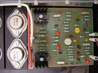
- Decoupling, The decoupling capacitors are just used for that, decoupling, not sampling. However, leakage currents cause massive distortion. High quality polyesterfilm or polypropylene will do fine. Keep wiring as short as possible.

- Differential mode, I inverted the data signal on one DAC. The first dac outputs L and R, the second one L- and R-. So basically I used 4 I/V converters that feed into a differential amplifier. Interference is significantly reduced this way and the output is DC-coupled since the offset voltage of both TDA1541A's is cancelled out.

- Filtering, I experimented for over a year with the most exotic filter setups. I finally used 2 closely tuned Allen key 3rd order butterworth-isch filters followed by a 2nd order MBF butterworth-isch stage. Filter was optimized for both flatness and linear group delay that's why I stated butterworth-isch. The sound is about the best you can expect from a 8th order filter. By the way, there is a nice filter calculation program available from TI.

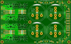
- Printed circuit board, Over the many years I designed hundred's of circuit boards (without autorouter), so this is a piece of cake. The twin DAC was placed on a single circuit board, but the new quad Direct Interpolation DAC will be a modularar design to achieve optimal results and future updates.

Well as you can see I can get quite enthousiastic about electronics.....Well that was it for now, I am pleased to join diyAudio. If you want more information about my D.I.Y. projects, please feel free to ask, your comments, tips and reactions are very welcome.

Messa Boogie Dual Rectifier

Hi

I am working on a friend's amplifier, Messa Boogie (Solo Head). He said the amp sounds dirty. What I noticed is that, there is severe crackling, popping and weird noises from the amp even without any signal present. It is present on all 3 channels. It gets worst if I turn up the volume or gain on each channel. I have isolated and checked all the electrolytic and orange caps, they are all within range. I did not check the tiny (picofarad) caps. I tried replacing all the 12AX7 tubes , one at a time with a good working preamp tube with no difference. Cleaned all the pots, switches and sockets with contact spray. I totally have no idea what is causing this problem. Can someone please guide me on what can cause such problems and what to check for. Schematics attached.
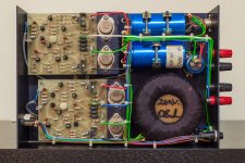
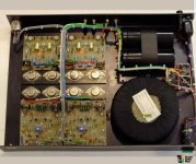
Thanks

Attachments

  • mesaboogie-dual-rectifier-3ch-solo-schematics.pdf
    220.9 KB · Views: 16
  • mesaboogie-dual-rectifier-schematics.pdf
    265.8 KB · Views: 15

Acoustic Horn Design – The Easy Way (Ath4)

Acoustic Horn Design – The Easy Way (Ath tool)

This is an associated thread for a waveguide generator called Ath (Advanced Transition Horn), version 4.
Ath is a piece of software for designing waveguides and horns. At the same time it makes it possible to easily simulate their acoustic behaviour by means of FEA (BEM) via ABEC/AKABAK tool.

The current Ath release is available at https://at-horns.eu


852187d1591950405-acoustic-horn-design-easy-ath4-render22-jpg


Thread milestones (last edited 26.12.2020, no longer maintained):

#233 Birth of the OS-SE formula
Acoustic Horn Design – The Easy Way (Ath4)

#375 Measuring driver's exit wavefront
Acoustic Horn Design – The Easy Way (Ath4)

#666 Some of the practical verifications:
Acoustic Horn Design – The Easy Way (Ath4)

#844 Ath 4.4.1 - Introducing superformula
Acoustic Horn Design – The Easy Way (Ath4)

#922 JBL M2 "How-to"
Acoustic Horn Design – The Easy Way (Ath4)

#933 JBL M2 - Ath clone
Acoustic Horn Design – The Easy Way (Ath4)

#1003 Comparison of an OS waveguide and a flat piston
Acoustic Horn Design – The Easy Way (Ath4)

#1117 Ath 4.4.3 released (Fusion 360 import)
Acoustic Horn Design – The Easy Way (Ath4)

#1533 Ath 4.5.0 released (scripts not backward compatible)
Acoustic Horn Design – The Easy Way (Ath4)

#1602 General phase-plug discussion
Acoustic Horn Design – The Easy Way (Ath4)

#2389 Joining profiles of different curvatures
Acoustic Horn Design – The Easy Way (Ath4)

#2494 Tritona Waveguide
Acoustic Horn Design – The Easy Way (Ath4)


Spherical-wave phase plug

#1706 Initial ideas
Acoustic Horn Design – The Easy Way (Ath4)

#1824 Kessito's input
Acoustic Horn Design – The Easy Way (Ath4)

#1892 Compression cavity modal analysis
Acoustic Horn Design – The Easy Way (Ath4)

#2016 Diaphragm suspension analysis
Acoustic Horn Design – The Easy Way (Ath4)


Free standing waveguides

#2600
Acoustic Horn Design – The Easy Way (Ath4)

#2936 Rolling back the profile
Acoustic Horn Design – The Easy Way (Ath4)

#3390 Employing axisymmetric BEM (finally)
Acoustic Horn Design – The Easy Way (Ath4)

#3427 Rollback added
Acoustic Horn Design – The Easy Way (Ath4)

#3532 Source amplitude shading
Acoustic Horn Design – The Easy Way (Ath4)

#3549 OS-SE formula extended: k
Acoustic Horn Design – The Easy Way (Ath4)

#3664 Effect of an enclosure and other parameters
Acoustic Horn Design – The Easy Way (Ath4)

#3822 Compression driver throat plug
Acoustic Horn Design – The Easy Way (Ath4)

#4186 Preferred in-room response and DI target (discussion)
Acoustic Horn Design – The Easy Way (Ath4)

#4503 Incorporating compression driver model
Acoustic Horn Design – The Easy Way (Ath4)

Attachments

  • ath4_UserGuide.png
    ath4_UserGuide.png
    138.5 KB · Views: 15,642
  • Like
Reactions: 10 users

What's wrong with the kiss, boy?

What's wrong with the kiss,boy ? ........ or - How I gained a gain ,little before Lee De Forest and little after Papa

lookie : Iron Pre | Zen Mod Blog

I already posted that link in few places here , but as it seems ,few Greedy Boyz are greedy for more info

cheap and clean way of having 6db (or little more ,with different gain device)

it's already everything written in that blog post , but to recapitulate :
-pot , then buffer of your choice , then 600:600 xformer connected as autoformer , voila! -there is 6db gain

if approach was good eons ago , when microfarrads and active gain devices were much more expensive than chunk of copper and iron,if approach is good for numerous mic input stages , if approach is good for F6 and especially M2 (buffer-autoformer-buffer) , it must be god for line stage too.

and yes , with 1+1 autoformer , Rout is four times Rout of buffer itself

xformers : Edcor have few , Jensen , Sowter, Lundahl etc.............

-do not expect that more expensive ones are necessary better sounding,
-do not expect maximum verity from buffer if you not use decent (shunt , my poison) reg.
-you can go wild and make your own autoformer , equipped with 24 taps , so skip pot on input and use autoformer at output, as volume attenuator and gain device ,as one device
-or you can make it this way - buffer -commercial AVC (200$ Slagle?)-output autoformer
-or you can go wild and connect commercial AVC to appropriate tap , as output autoformer and have 6db gain ...... that would be buffer -commercial AVC connected on proper tap

now I'm working on balanced Iron Pre ..... will post that soon too

edit on 11.10.2020. : last files for SE and Bal iteration are in posts #1149 and #1150

The 15 Song Album collection:

Hi to all,

I just want to make a album for 15 songs time over 16 minutes. It's simple. Each user has to copy and paste adding only one song to the album so in the end it's 12 songs, one per user, and each album has to have a different theme.

Whoever adds the last song of the album gets to say what the the theme for the next album will be and it starts all over again.

Songs over 16 minutes:

1. Pink Floyd - Echoes (23:31)
2.
3.
4.
5.
6.
7.
8.
9.
10.
11.
12.
13.
14.
15.

Change A 6L6 400 volt amp to EL34 tubes ?

Ive started building with a 400 volt PT 6L6GC PP amplifier for a guitar and I was thinking about changing the power tubes to EL34 tubes and keeping The 6L6 tube rectifier A 5U4GB ?, My question is this; Is it going to be enough power for the tube swap ? . And Should I get rid of the rectifier tube ? . My donar is a 1960 Whirlizer 501273 organ Amplifier. 501426 PT and a 500882 OT . And For The Pre Amp section I was going to copy The Original Sunn Model T. I'm building a pretty thick Aluminum chassis for it right now. I have it made already but it still has to be Tig welded together. I'm trying to get a hand sensitive deal going with this thing. Just Looking for a few ideas before I start assembling it and I actually start cutting into the new chassis. I have already tested the transformers and everything looks good with both of them. The negative bias is A little bit weird it's using 1/2 of A 12AX7 tube. It took me a little while looking at it to figure that out. I'm New on here. Hi to everyone !

Exploring Purifi Woofer Speaker Builds

A thread for discussion on all purifi driver builds.

A place to brainstorm and speculate on drivers and potential speaker builds for arguably, objectively, the best no-nonsense engineering-first traditional speaker drivers' money can buy - If you have a complete project underway, please start your own thread and post a link to it in here. Otherwise posting occasional random progress pics and info here is fine but we will keep full build discussion elsewhere.

We are also pleased to have @lrisbo of purifi occasionally check in and post here of which is much appreciated.

A tweeter is on the way :geek:

Updated 26/01/23: Added more build links and intro - (I may stop updating commercial builds moving forward as they are now coming in thick and fast)
Updated 16/06/22: Added builds and review links, updates to builds
Update 17/03/22: below


Time for a bit of consolidation due to this thread getting some hits, and purifi has now released quite a few scrunchy woofers

Links to known projects & commercial speakers using the Purifi drivers (please PM me if I need to add any)

Of course - www.purifi-audio.com , and the team behind the drivers here


Full DIY:

DIYA user @spresto9 has come up with these beauties with the 8" purifi woofer like to details and more pics HERE

20230125_122405-jpg.1134630


Check out this 4" pocket rocket proof of concept build from the Purifi team - all the info you need to DIY!

Spk8 appnote download (.pdf)

1649857222609.png


@lrisbo Proof of concept Purifi SPK4 (superseded) - Passive stand-mount

IMG_0194-2.jpg


@lrisbo Proof of concept Purifi SPK5 - Passive stand-mount - I believe these were at some point being made and sold commercially but have since been discontinued - there may be some floating around second hand market see here Celuaris SPK5 review ASR

purifi_spk5.jpg


@xrk971 PTT6.5/RS28F Waveguide Harsch XO - Passive stand-mount later evolved into a nice Stand mount and Floor standing Transmission Line

ptt6.5 rs28fwg.jpeg


@Joe Rasmussen Somewhat Legendary 'Elsinore' - Has been given an (expensive) purifi remodeling. Wow. Skip ahead to post #4,746 for the juicy bits.


Outback_Red_Populated_710W.jpg


Rick Sykora and team's Directiva - Active stand-mount with excellent (objective) reviews, requires external amplification for each driver and an external DSP crossover.

ASR Directiva Review Open Source Purifi Speaker.jpg


@xrk971 's Raal 70-20xr and PTT6.5 - this one the tweeter is not readily available to DIYers but there may be ways to get it if you're crafty.

(sorry X, couldnt find a finished pic, and I'm out of attachments for this post)


User tktran303's Collection of DIY designs here looking great

844c090c-c096-458a-a63d-a313c999c778-jpeg.1090990


Some mindfood for the 8" - a concept by Purifi.

1670006638175-jpeg.1115978


Paul Carmody's Virage - a full design, light on measurements but a fairly reputable designer.


.....and many more concepts within this thread, start reading. Most not fully documented or taken to finished stage though I suspect a few people are still perfecting their builds before showing them off. Remember you can drop people a friendly private message asking about how their progress is going.


DIY-Kits/Semi Commercial:


Yevgeniy’s PuriWave - 2-way stand mount with dual purifi passive radiators

PuriWave_banner_page.jpg


Troels Gravesen Purifi 6661 - Semi-passive/Active plate amplified floor-stander

p-6661-1.jpg


Troels Gravesen Purifi 6R - Passive bookshelf

purifi-1.jpg


Troels Gravesen Purifi Be - Looks like a revision to the above due to ribbon tweeter supply issues.

finished-1.jpg


hificompass Puri Bliss BeWg - Passive bookshelf - I believe the plans are/were for sale.

PuriBliss_BeWg_4.jpg


Joseph Crowe's 1198 - I believe you have to get in touch via the webpage - floor-stand transmission line

110749662_1199955657029489_1368727901282454175_n.jpg


Full Commercial:

March Audio Sointuva - arguably where "the bar has been set" for the Purifi 6.5 in a bookshelf chassis.

Sointuva17.jpg


Jones Scanlon Baby Reds - self powered studio mixing monitors.

Jones-Scanlon-Baby-Reds-studio-monitors-1920w-2.jpg


The Late Rick Craig's Selah Audio Purezza - A nice stand mount ribbon tweeter design, was available commercially but afaik discontinued, check SH market

116706749_971365439969612_5078393334836774399_n.jpg


Jachim Gerhard Surveyor's - stand-mounts , I believe there is/was a floor-stander made too

Rose_03-10-2020_0025-scaled.jpg


Dennis Murphy & Jim Salk's BePure2 - Floor stander - The legends behind the philharmonic BMR and BMR tower

a.jpg


and um, what ever this might be! https://www.audiocircle.com/index.php?topic=175599.0 - probably just a concept, I didn't read the thread. Likely Unobtanium tweeters and probably bottomless pockets required, if it is sold commercially.

Correction - the above was a concept which later evolved to the BePure2 - see this thread at AVSForums Post #10,174
https://www.avsforum.com/threads/th...rs-and-discussion-thread.939744/post-61186397


Further Build links:

Thrax Siren - a 2-way standmount

Jern 35 - 2 way standmount

Buchardt A500 Signature - Active 2 way standmount

WVL Serendipity - 2 way standmount

Taipuu Kero L active with FourAudio PPA-1000 dsp amps. - Not sure if available yet

Salk Sound BePure3 ... Holy **** I need to hear these.

a.jpg


Links to independent driver reviews:

https://www.erinsaudiocorner.com/driveunits/purifi_4/
https://www.erinsaudiocorner.com/driveunits/purifi_ptt65w04/
https://www.erinsaudiocorner.com/driveunits/purifi_ptt80x04-nab-02/ - the eight inch aluminum mid-woofer
https://www.erinsaudiocorner.com/driveunits/purifi_ptt6.5x04-naa-08/ - the 6.5 inch aluminum mid-woofer
https://www.erinsaudiocorner.com/driveunits/purifi_ptt6.5m-08-nfa-01a/ - the 6.5 inch dedicated midrange

Also - please consider visiting Erins Youtube Channel and subscribing! - a much needed light in the dark world of audio subjectivism.

https://audioxpress.com/article/tes...udio-6-5-midbass-transducer-from-purifi-audio

https://hificompass.com/en/reviews/purifi-audio-ptt65w04-01a-midwoofer
https://hificompass.com/en/reviews/purifi-audio-ptt40w04-01a-midwoofer
https://hificompass.com/en/reviews/purifi-ptt65w08-01b-ptt65x08-nfa-01
https://hificompass.com/en/reviews/purifi-ptt65m08-nfa-01a-65-true-midrange

http://www.troelsgravesen.dk/Purifi.htm


Original Post 02/04/2020:

With the group buys well underway the idea was bought up that a design thread be started to discuss build options.

Mine have arrived but I have no build materials and will not be able to get any until we come out of quarantine in (hopefully) three weeks time. I planned to start with a hybrid of purifi's SPK4/5 builds using the same AMT tweeter but maybe using a slot port with the 2.5khz crossover. That and I haven't done any AMT builds so it seemed like a good place to start.

I read of a guy in Aus planning on doing a line of passive and active speakers with the woofer so be interesting if he could chime in here.

So with no materials for the next at least 3 weeks, what better time to discuss build options! Fire away


20200402_103700.jpg
20200402_103908.jpg

Attachments

  • IMG_0194-2.jpg
    IMG_0194-2.jpg
    98.6 KB · Views: 457
  • purifi_spk5.jpg
    purifi_spk5.jpg
    229.2 KB · Views: 471
  • Like
Reactions: 5 users

Hafler DH-500/P500 Mods

Time to start this long over due thread
I just need to find one now :p
Maybe the posters in the DH-200/220 Mod thread can use this thread instead for these models :D
We are working on adapting the DH-220C design for use in DH-500 & P500 chassis
There are some new OPS boards in trial for those heatsinks.

Attachments

  • 1069690-hafler-dh-500-audio-power-amplifier-made-in-usa.jpg
    1069690-hafler-dh-500-audio-power-amplifier-made-in-usa.jpg
    130.1 KB · Views: 1,722
  • hafler-p500-power-amp_2.jpg
    hafler-p500-power-amp_2.jpg
    47.3 KB · Views: 1,433

Aleph Jzm for the diyAudio Store

IMG_5534-2.jpg


Aleph Jzm kits will be available in the diyAudio store when the new store goes live at 10:00pm CST in the USA. This thread / post will be updated with additional details as they become available.

What Is An Aleph Jzm?

The Nelson Pass designed First Watt Aleph J is a classic. @Zen Mod created this version of the Aleph J to make the project more approachable to newer builders while maintaining the characteristics of the original. For more advanced DIYers and those that like to experiment, there are options to use a variety of JFETs and customize the circuit to suit personal tastes. For those that don't know Zen Mod, he was gracious enough to post a video to introduce himself and share a few thoughts. It can be found here.

What’s In The kit?

All the electronics components needed to complete a pair of amplifier PCBs, including 8 matched JFETs.

IMG_5118.jpg

What Is Needed To Complete The Full Project?

At this time, a complete kit including everything required to complete an amplifier is not available. You’ll need a power supply, chassis, wiring, and a few other parts. Everything you need can be purchased directly from the diyAudio store and well-known retailers world-wide. Suggestions are included in the build guide, and/or you can customize to your heart’s content.

What Skill Level Is Required?

This project is intended for intermediate to advanced DIYers. It may be the perfect project after an Amp Camp Amp. Newer builders willing to do a little studying should have no trouble following the build guide. However, it is critical that builders know how to identify parts from schematics, match those parts to PCB locations based on the silkscreen, and have good soldering skills. Most importantly, all builders are responsible for their own safety and must understand essential safety practices and precautions when dealing with mains powered electronics.

Feel free to review the Aleph Jzm Build Guide in advance if you're trying to determine if this project might be for you. The guide will continue to be updated. A dedicated builders’ thread will also be created for additional support.

I’ve Heard There Is A Chassis For The AJzm

It’s not only for the AJzm; it just happens to work really well with the AJzm. More details can be found here.

More to come....
  • Like
  • Thank You
Reactions: 12 users

Carver Receiver 900 User Manual. Can find service manual, but not user manual.

Looking for Carver Receiver 900 User Manual. (NOT PM900 or other XX900, just plain old 900.) Can find service manual, but not USER manual. WiFiEngine website says it has the user manual, but new registrations are closed permanently so can't log in to get it. Electrotanya doesn't have it. Any suggestions? Thanks.

The dome midrange thread

As the title states, this is a thread dedicated to dome midrange drivers, specifically any larger dome driver at least 50mm or 2" in diameter intended to be used in a 3 way or larger speaker design.

Being there isn't a good collection of data on this rather rare type of driver and its use, it would be nice to have it all in one thread. My goal was to give anyone interested in the successful design of a speaker using a dome midrange a solid starting place to gather or share the info necessary to design a new speaker or to modify an existing design to use them ie. xover, baffle modifications, etc.

If you have any specific or technical info (measurements, graphs, data, xover design, pictures, links etc) regarding your favorite dome midrange or a specific technical question, please feel free to share it in this thread.

Please keep your post to the point and avoid any strong subjective opinions. I was hoping this thread could accumulate as much relevant info as possible. Thanks in advance for any productive shared info.
  • Like
Reactions: 11 users

Xsim Mod Delay Question

Hello everyone,
I have been messing around with Xsim for a 2 way xo design and I am a little confused about the results I get with the mod delay. I am using a 5.5 inch woofer (sb15 nrx) and a morel mdt29 tweeter on a Visaton waveguide. I measured the drivers individually and then I made a combined measurement with the drivers hooked up in parallel. I loaded the individual FRDs and then the combined response on top, to match the curves using the mod delay.


The waveguide I am using (WG148) isn’t particularly a deep one, therefore the tweeter’s voice coil is still in front of the woofer’s. The offset is around 25mm (or an inch give or take). As far as I know, you have to apply positive mod delay on the woofer side if the tweeter’s voice coil is in front (which is the case for most of the applications). In my case however, only when I apply a little bit of negative delay the curves begin to match.

Here is the response differences before the delay is applied:
WhatsApp Image 2024-05-17 at 14.15.35.jpeg


and this is after the negative delay value is applied:

WhatsApp Image 2024-05-17 at 14.15.27.jpeg


Is this normal? Am I missing something or did something wrong?

Thank you all in advance.

Does this explain what generates gravity?

Click this for the scientific paper.

This is the Abstract:
Quark movement is almost by the speed of light. Due to this speed their inertial mass-effect increases profoundly. That inertial effect is an accelerating force. Within the nucleon the force is the strong force. As quarks movements are back and forth movements, called zigzag or oscillating movements, there is movement in opposite directions. So the oppositely acting forces annihilate each other. However the force acting on objects receding from each other is a trifle stronger than that acting on objects approaching each other. This small difference between these forces is a “left over” force and “leaks” out of the nucleon. In previous manuscripts, formulae were presented to calculate these forces. In the present paper the “left over”, “leaking” force is estimated, and this force is gravity.
  • Like
Reactions: 2 users

Ideas input for a Interstage driven 300B SET

Hi,

First post here after reading many interesting and enlightening topics. I’ve just finished a simple 45 amplifier, and was so positively surprised I decided to build a second amp. This so the 45 can do what I built it for: drive my headphones in the office.
I just made the mistake of trying it on my speakers and despite their low efficiency the sound is so addictive the amp is not moving to the office until I’ve built a proper “speaker” amp!

So here we are, I’d like to build a 300B amp: I’ve acquired a pair of tango NC20 interstage transformers (original make) and have a set of Audio-note Output transformers (single ended). All I need is a schematic :)

I do like the idea of keeping everything DHT and simple, because then it’s easier to grasp given my limited knowledge and philosophically I like simple: also this would allow me to study the effect of swapping individual components to tailor the sound. (I’m not looking for something that measures well per se, it should sound well, not for opening that discussion:) )

I like the 45 sound but that probably has too little amplification to keep it two stages, which would be the preference, also one could avoid coupling capacitors but am open to be convinced otherwise. Should I look at a 10y? EML 30a?

In any case curious to hear peoples thoughts.

Cheers!

Matthew

Sica 5" and 6" hifi coaxials measurements

I have decided to publish full measurements of those good performing coaxial drivers. Coaxial drivers is quite a buzzword nowadays, we all know that the concept generally is very good and has benefits, though real life coaxes suffer from a lot of issues, measured performance is far from ideal. and prices are quite high.
I created 2way loudspeakers from both, and 3way from 5" coax + 6" Sica woofer. Based on listening impressions, feedback from hifi friends, and measurements, those drivers are ones of better coaxes available on the market, and Sica did the engineering right. Both sound very good and make good two way loudspeakers and definitely make good midrange-tweeter for 3ways.
Sica 6.5H 1.5CP
Sica 5.5H 1.5CP

Measurements were done in small enclosures with R28 front baffle edges, mic distance 1m for FR and 30cm for distortion, gating 10ms, SPL calibrated, measurement voltage 2.82V, microphone Earthworks M30.

5" coax assessment:
  • 3kHz dip in tweeter response is trouble and not nice to look at. It makes crossover design quite challenging. Off axis responses are consistent so the issue is correctable with active crossovers.
  • distortion performance is good for basic drivers and does not suggest any big issues
  • tweeter top end response is not perfect, though is much better then what we usually see from other coaxes
  • we had side by side comparison with KEF LS50, LS50 measurements showed elevated 3-kHz area if I recall well. Sica sounded better in all aspects.
6" coax assessment:
  • 3kHz dip again. Off axis responses are consistent so the issue is correctable with active crossovers.
  • distortion performance is good for basic drivers and does not suggest any big issues
  • tweeter top end response is not perfect, though is much better then what we usually see from other coaxes
  • I attached also Vituix 6pack for completed 2way passive loudspeaker, this version sounds very good, has reasonable low end extension and overall listening impression and feedback was there was something really right and good in the sound
  • small wrinkle at 800Hz is front port interference
Both are visually very nice drivers, though some details are not perfect, for example consistency of the glue ring and surround centering.
I am also glad they use paper cones with some kind of coating, which means less severe breakups and generally better sound then alu cones (I am not a fan of KEF sound at all, though I admit Meta versions might be step in the right direction to better sound)

Crossover design for both was not easy due to 3kHz tweeter response dips. Standard two way 6" + WG is much easier. Acoustic LR4 at 2000-2500Hz is mandatory due to a) tweeter: rising distortion <2kHz, b) better directivity match, c) uneven response of midwoofer >2.5kHz.

I have lived with those 3 loudpeakers/projects for ~2years and have a lot of experience and comparison to standard 2ways and 3ways. They sound very good and for the price there is very little to complaint about. But ClassIllu 2way (Scan Speak 18W/8545K00 + 6600) beats it in every aspect. It is not fair comparison, ClassIllu drivers cost is much higher, though it tells me that coax is not the only feature that makes a good sound or would be the only prerequisite for the good sound.

Attachments

  • Sica 5inch koax midwoofer dist.png
    Sica 5inch koax midwoofer dist.png
    72.7 KB · Views: 601
  • Sica 5inch koax midwoofer horiontals.png
    Sica 5inch koax midwoofer horiontals.png
    103.5 KB · Views: 512
  • Sica 5inch koax tweeter dist.png
    Sica 5inch koax tweeter dist.png
    44.1 KB · Views: 495
  • Sica 5inch koax tweeter horiontals.png
    Sica 5inch koax tweeter horiontals.png
    88.1 KB · Views: 496
  • Sica 6inch koax midwoofer dist.png
    Sica 6inch koax midwoofer dist.png
    73.7 KB · Views: 542
  • Sica 6inch koax midwoofer horizontals.png
    Sica 6inch koax midwoofer horizontals.png
    102.2 KB · Views: 505
  • Sica 6inch koax tweeter dist.png
    Sica 6inch koax tweeter dist.png
    41.8 KB · Views: 560
  • Sica 6inch koax tweeter horizontals.png
    Sica 6inch koax tweeter horizontals.png
    88.4 KB · Views: 576
  • Like
  • Thank You
Reactions: 29 users

Kind request of help _ basic but low THD discrete buffers

Hi ! i am just a beginner and please be free to move this thread to a more proper location :rolleyes:
i have a question about bjts buffers
Is it possible to get low THD buffer from very basic discrete circuits ?
I am attaching an example of what i mean
I am noticing that using a npn and a pnp together instead of using just one bjt as a common collector there is a sort of THD cancellation ?
Is this a general effect ?
I have already a schematic of a decently low THD buffer ... if i add another branch mirroring it (i.e. replacing npn with pnp and viceversa) could i get even lower THD ?
Thank you very much to All
gino

Attachments

  • bjt pair buffer.asc
    2.6 KB · Views: 19
  • buffer fft.JPG
    buffer fft.JPG
    144.6 KB · Views: 12

Does this variant of Zen Variant 1 work?

Hello everybody! This is my first post here, and also, I am very new to the hobby of electronics so please bear with my misunderstandings.
I am thinking about implementing Figure 5 from Zen Variations 1 but with my own twist.
https://www.passdiy.com/project/amplifiers/zen-variations-1
zenlite_9.png

The twist is that instead of using a lamp and the whole circuit between the lamp and positive voltage as in Figure 5,
I will be using a benchtop PSU with constant current at 2A and raising it to 12V.
So the positive of the PSU will be where the lamp is instead of the lamp.
I think 12V 2A matches the conditions specified in the article but I am not entirely sure.
I want to know if this substitution is possible.
The article says you need a constant current source but
I am very new and unsure whether my benchtop qualifies as the 'constant current' source needed.


I have some more questions.
The output in Figure 5 is just a node hanging off to the right.
I have an 8 ohm full range speaker. Do I attach the speaker from 'OUTPUT' to ground?
The input in Figure 5 is just a node hanging off to the left.
Do I attach the positive of my PC audio cable splitter to 'INPUT' and the negative to ground?
(These grounds are all going to the negative of my PSU).

'The electrolytic capacitors should be voltage rated at the supply voltage, which in this project can vary from 40 to 80 volts DC.'
Also, I see my two electrolytics are rated at 25v and 35v, higher than the PSU's 12v but lower than the article's supply voltage at 40v-80v.
Could this be a problem?

Thank you.

Those Magnificent Television Tubes

There are a lot of these tubes out there. I don´t mean the picture tube, but all the other ones. F. ex. the well known audio tubes 6CG7, 12BH7 and 6CW7 etc. are actually designated for TV-sets.

There are a lot of other quality tubes in Europe & US, costing almost nothing, like PL84, ECF82, PC86, PF86 ECF83, PL81 etc (P stands for 300mA heater current & E for 6,3V voltage)

F.ex. the EC/PC86 triode will outperform ther popular ECC88/6922 types with lower noise and higher gain & linearity.

In US there are 450 & 600mA heater current tubes I think.....(due to 115V mains & series connected heaters)

When a manufacturer sold a tv-set with 20-30 tubes and guarantee, the incorparated tubes have to be of very high quality.

If you have made an amp or other things with these tubes, please give a hint or schematic diagram in this thread.

Regards, Johan

Wordle

When I was young, we spent hours on end playing what we called word game. Same rules but it was always 4 letter words.
I was introduced recently to this new sensation and tried it today. Now I know it's beginners luck, but first time out I got it in 3 words.
I think I'll try again and let it bring me back to earth.
Who else is doing this?

Attachments

  • DSCN8507.jpg
    DSCN8507.jpg
    65.5 KB · Views: 982

Dual Acoustic Elegance 15SBP-8A in sealed enclosure

I am planning on building a bass enclosure for using with various horn designs I am working on.

I have four AE SBP15-8A. 15", 8ohm, Apollo upgraded woofers at hand. When I model them in winisd for a dual woofer enclosure, I get 449,43lt volume having a Qtc of 0,703 and a Fsc of 35.93hz. This is very fitting for me. I will put Hypex FA501 on each enclosure so I can send 250w @ 4 ohm to each woofer. I plan on crossing to horns to lowest around 300hz and to highest around 600hz depending to the horn I am matching it with.

My questions are about the baffle width, shape and the enclosure edges. Should I make it as narrow as possible or should go for some gain from the baffle and make it wider. Shall I make the enclosure non symmetrical. Do I need chamfered edges? I would appreciate any input, thanks.

OPA1612 from Aliexpress, no counterfeit but why so cheap?

After working with some OPA1612 on my recent Topping PA5 D01 Module replacement project (at ASR),
a friend sent me a few OPA1612 opamps he ordered when they were in stock since i couldnt get them anywhere.
alongside with some aliexpress el`cheapos for like 2 buck a piece instead of 7..8 bucks for a genuine part.


i expected them to put some cheap crap in there, so i didnt wanna use them.
but was curious whats in there, so i opened one up.. surely they have put a tl072 or ne5532 in and relabeled it..
turns out, after extracting the Silicon Die, they are genuine.

Do they not meet the manufacturers specifications and are rejects or something else?
nothing my budget equipment can measure, but they worked fine, didnt have any louder hiss than the original parts and didnt oscillate or anything, even power draw was about the same.

this was from two different sellers at two difference price points on aliexpress, it doesnt mean everyone on there sells genuine parts.
i now ordered some more for like 80 cents a piece to see, whats going on with them. gotta wail til they arrive.

hearing them vs. the genuine part thats in spec, isnt conclusive either, its differences are so minor, my ears cant pick them up.


Original (mouser):
e-CAMView_slg6h7xnyD.jpg

from a device that used them (actually the topping i mentioned above, extracted from the module)
, the damage to the right might be due to my extraction methods.. this chip is barely a millimeter in height and im not using any chemicals.
e-CAMView_yRq9xU3HZe.jpg

Aliexpress seller 1
e-CAMView_iZIC86G8BN.png

Seller 2

e-CAMView_2v5ejO3UXO.jpg


(zoomed out, not to scale anymore)
for comparison, a genuine OPA1656
e-CAMView_eduvzjgvg3.jpg

Ti NE5532
e-CAMView_ePdV66W06X.jpg

TL072
e-CAMView_JxvDlIdIWq.jpg
  • Like
Reactions: 1 users

QUAD 63 (and later) Delay Line Inductors

There was some interest in another thread about the modern Quad inductors that form a portion of the delay line in the 63's and newer Quad electrostatic loudspeakers.

Strangely, the British electronics in these speakers is quite robust. But over the 24+ years I've been fixing quads, i've seen just about every failure you can have. I've only seen a couple damaged inductors and they were the results of massive overdriving of the speaker. Below is my knowledge of these inductors, although I haven't really dug into them very deeply (both metaphorically and physically) which you'd want to do if you were going to reproduce them.

The inductors are air core units with a second shorting winding that increases the inductance dramatically beyond what a single coil of this size and wire gauge is capable of. The inductance is about 2.7H each if my measurements are correct. The attachment below shows my method and results. (NOTE: The DCR is in Kohms not ohms as noted on the sheet. And I went back and re-measured the inductor resistance and got the same numbers as the first two inductors; I beleive all inductors are identical). I used a function generator, a resistor and a voltmeter to measure the inductor by forming an AC voltage divider. Using the fact that and inductor has an impedance of: Z = 2 * PI * f * L, I was able to calculate L because I know, Z, and f.

http://quadesl.com/diyaudio/inductorCalc.png


As seen in the pictures, the copper coil is sitting in a plastic "bobbin" with three leads which are soldered to the delay line circuit board. The entire bobbin, and actually the entire delay line circuit board is encapsulated in bee's wax which makes these things easy to work on.

Two of the leads are connected via a buss bar inside the bobbin, and the third (middle) lead runs from the center of the coil. The shorting coil is attached to both the left and right attachment points on the buss bar (forming a short through that bar. And the main inductor coil is attached to one side of the buss bar, at the outside of the coil and the other end is attached to the center lead coming from the middle of the coil.

I don't have a feel for how the shorting coil is arranged relative to the main coil. I'd think it would be bifilar wound, but I have never completely unpotted one of these to check it out.

The way I've seen these fail is that the very fine wire breaks near the solder connection at the buss bar. It appears that the wire overheads and melts, but on come specimens the wire looks thinned which doesn't make sense with a pure melting failure mechanism.

To fix them, I melt the wax around the buss bar and in the center of the coil and using a short piece of jumper wire, I re-solder the fine magnet wire to the jumper and then the jumper to the buss bar. I use the jumper wire because without un-potting the entire coil, the wire where it breaks is too short to reach the buss bar.

Here's a couple pictures of the inductor including one through my stereo-microscope eyepiece. Taking a picture with my cell phone through the eyepiece is a real kludge but works reasonably well to document things.


http://quadesl.com/diyaudio/IMG_4075.JPG

http://quadesl.com/diyaudio/IMG_4076.JPG


Sheldon
quadesl.com
  • Like
Reactions: 1 user

Transmission line speakers I have never seen before. Need help to figure every thing out

Hello im Barry. I have just bought a pair of tl speakers. The crossovers I need to figure out which wires correctly go to which driver. It's s design iv never seen before. Hopefully the pictures will help

Attachments

  • IMG_20240512_184439.jpg
    IMG_20240512_184439.jpg
    340.6 KB · Views: 237
  • IMG_20240512_184404.jpg
    IMG_20240512_184404.jpg
    310.5 KB · Views: 238
  • IMG_20240512_184418.jpg
    IMG_20240512_184418.jpg
    283.2 KB · Views: 235
  • IMG_20240512_184433.jpg
    IMG_20240512_184433.jpg
    139.7 KB · Views: 213
  • IMG_20240512_184451.jpg
    IMG_20240512_184451.jpg
    295.7 KB · Views: 232

A Monster Construction Methods Shootout Thread

Which wood to use? Which fill? What does bracing do? Is CLD best? I'm starting this project to start quantifying some answers to these questions. A lot of work has been done before in fits in starts by others (BBC, Kef, etc.) but they were often narrow investigations and you couldn't compare results because measurement conditions were different among the different studies. Some have cited manufacturer's damping specs, but I have no idea how that translates to the real world. Ditto on accelerometer data. So here I will be doing SPL measurements, that is after all, what we actually hear. The cabinet is ordinary, large enough for the panels to have some radiating area and magnify differences between changes.

QcoRN7K.jpg


I will be using a Peerless 830970 firing into the cabinet using MLS signals. I have to test mic placement, but it will probably end up near-ish field, probably at a side panel. When I do the fill/lining I will mount the SB15 as a dummy woofer and measure what radiates through it. I intend to measure SPL, CSD, and THD. Any other recommendations appreciated.

For the material test I currently have: high and low quality plywood in 1/2" and 3/4", and MDF in 1/2" and 3/4".

For the fill and lining I have: SDS CLD tiles, AcoustX coating, denim insulation, polyfill, 1" thick dacron blanket (what the TL guys use) and Sonic Barrier.

For bracing I will do: simple oak crossbrace versus oak crossbrace using CLD construction with Sikaflex 292i adhesive. I also have some microspherules to combine with the adhesive to see how that changes things.

I would appreciate all suggestions on any other additions to the above. A priority will be that the materials must be widely available and reasonably priced, and the methods must be accessible to an ordinary DIYer.
  • Like
Reactions: 1 user

Darlington rangemaster Ge to Si

Hi all, I have been rocking this darlington rangemaster circuit for at least half a decade now and I am tired of replacing the germanium transistors bi-annually. I installed some 2n3904 in place of the MP44s I usually use and the circuit just sounds extremely "farty" and not in a good way. There is consistent signal but just really distorted in a bad way (like way worse than the difference between Ge and Si would give).

Changes I have made to the attached circuit (and used for years): took RC out for maximum gain, RD is 15K and RE is 3.3k.


Any thought what could have gotten messed up?
darlington.png

Philips CD-960 tray won’t eject help!

Hi all I recently got a Philips cd 960 in lovely condition unfortunately it’s not working

The tray will not eject when pressing the button however it closes when you manually open it and press the close button

It doesn’t play CDs however when the cd is seated it spins for a few short seconds and then stops

I have replaced the 4 belts with the nanocamp kit carefully and lubricated the shafts and motors when I press the open button I don’t even feel the two spindles with the wire try to move to support it opening

I used the drive wheel space to minimise movement when replacing the belts

Any ideas where I can look next to get this cd play up and running?

Attachments

  • IMG_3026.jpeg
    IMG_3026.jpeg
    368.1 KB · Views: 33
  • IMG_3024.jpeg
    IMG_3024.jpeg
    314 KB · Views: 32
  • IMG_3021.jpeg
    IMG_3021.jpeg
    395.7 KB · Views: 29
  • IMG_3022.jpeg
    IMG_3022.jpeg
    431.5 KB · Views: 31

All open baffle

Anyone heard these Italian crazy looking all open baffle speakers? How can they produce enough low bass?

Attachments

  • 77589-dccaa17f5ab79c4e47c5d152d82fc8a4.jpg
    77589-dccaa17f5ab79c4e47c5d152d82fc8a4.jpg
    95.4 KB · Views: 562
  • 77583-4b370a316e738ea14a47a54d85258eb1.jpg
    77583-4b370a316e738ea14a47a54d85258eb1.jpg
    57.5 KB · Views: 543
  • 77581-d1b6f5ab0bad960f34d8a8bddf1c96f6.jpg
    77581-d1b6f5ab0bad960f34d8a8bddf1c96f6.jpg
    125.4 KB · Views: 560
  • IO-naked-hifi-news-munich-may-2023-feat-1024x576.jpg
    IO-naked-hifi-news-munich-may-2023-feat-1024x576.jpg
    59.9 KB · Views: 596
  • IO-naked-hifi-news-munich-may-2023-3.jpg
    IO-naked-hifi-news-munich-may-2023-3.jpg
    47.4 KB · Views: 648
  • 77584-268d2cece186274946b3f55f104b0d9f.jpg
    77584-268d2cece186274946b3f55f104b0d9f.jpg
    39.4 KB · Views: 486
  • 77585-8c3c83ad5bd04c33b27988144f3a04b5.jpg
    77585-8c3c83ad5bd04c33b27988144f3a04b5.jpg
    41.9 KB · Views: 530

DIY Class A/B Amp The "Wolverine" build thread

This thread is for people to discuss their builds, build issues, and parts for the DIY Class A/B "Wolverine" Power Amplifier.
The boards are currently available through group buy's when they are held.
@jjs is servicing the USA and Canada regions.
@stuartmp is servicing the other regions.

Main Thread:

Wolverine 57v & 64v Schematic:
Please see the attached PDF files. These schematic show.
The Wolverine IPS - V3.7 (1st Group Buy) & V3.8 (2nd Group Buy)
The Precision EF3 - Both
EF3-3 (3 Pairs of Output Transistors) - V3.9 (1st Group Buy) & V4.0 (2nd Group Buy)​
EF3-4 (4 Pairs of Output Transistors) - V3.9 (1st Group Buy) & V4.0 (2nd Group Buy)​

BOM and Build Guide documentation:
Currently only available to group buy members.
In time will all be posted publicly once the group buy members have had time to order parts.

YouTube Build Link

Google Photos - Wolverine Build Album

Review Attached by @fireanimal 30-06-22
Review Attached by @richbandit 05-08-23 or at post
#2,493

Posts of Interest
#

There is also a distortion sweep plot of the Wolverine below with the values listed for 1K, 10K and 20K.
A big thank you to Andy for taking this measurement for us. 🙏

17-3-23
we finally have 20k distortion measurements.
0.000095% THD 80 watts 8 ohm load.
Thanks again Andy for providing these amazing results
More test results can be found at the end of the build guide.

-------------------------------------------------------------------------------------

We are happy to announce a 2nd group buy opportunity has now opened. :)

We have received the 2nd GB boards and have a few left over. If you'd like some boards from the wolverine project please follow the instructions in the 1st post of the 2nd group buy. Link below

The Wolverine 2nd Group buy.

Attachments

  • Recommended PSU Information.png
    Recommended PSU Information.png
    14.3 KB · Views: 3,323
  • 20221101_175426~2.jpg
    20221101_175426~2.jpg
    650.4 KB · Views: 3,073
  • 20221110_160311.jpg
    20221110_160311.jpg
    621.2 KB · Views: 3,315
  • IMG-20220626-WA0019.jpg
    IMG-20220626-WA0019.jpg
    152.9 KB · Views: 3,850
  • DIYAWolverine IPS Template.zip
    15.6 KB · Views: 760
  • IMG-20230317-WA0002.jpg
    IMG-20230317-WA0002.jpg
    303.9 KB · Views: 2,365
  • IMG-20230317-WA0001.jpg
    IMG-20230317-WA0001.jpg
    282.3 KB · Views: 1,654
  • IMG-20230321-WA0000.jpg
    IMG-20230321-WA0000.jpg
    257.2 KB · Views: 1,378
  • SMPTE.png
    SMPTE.png
    61 KB · Views: 1,299
  • DIN.png
    DIN.png
    58.1 KB · Views: 1,200
  • CCIF.png
    CCIF.png
    54.8 KB · Views: 1,150
  • 1k5.5k.png
    1k5.5k.png
    56.3 KB · Views: 1,232
  • multitone.png
    multitone.png
    107.9 KB · Views: 1,851
  • 2nd GB DIYAampEF3_wolverine Schematic Version 4.3 (10-06-2023) 57V Rails.pdf
    147.6 KB · Views: 878
  • 2nd GB DIYAampEF3_wolverine Schematic Version 4.3 (10-06-2023) 64V Rails.pdf
    162.7 KB · Views: 732
  • Wolverine Amplifier review by richbandit.pdf
    101 KB · Views: 640
  • Wolverine Amplifier review by fireanimal (Andy) 30-06-2022.pdf
    972.3 KB · Views: 532
  • Wolverine Precision EF3 Build Guide revision 41 (07-10-23).pdf
    7.2 MB · Views: 907
  • Like
  • Thank You
Reactions: 12 users

Aleph P1.7 assembled board

Aleph p1.7 completed board for sale.
Solid brass bar keeps all mosfets equally hot, relays are itt, gain fets are harris devices, attenuator section uses sfernice resistors and some nos siemens 0.1% resistors. In/out capacitors are roederstein mkc, capacitance is smaller than advices 10uf, but if load is not tough its alright.
Ps photos are from construction, bad soldering on adc chip is corrected.
Asking 230 euro.
Board size 20x30 cm


20230820_180043.jpg
20230924_114029.jpg
  • Like
Reactions: 1 users

Buzz kill

Hello, I have just rebuilt an old Playmaster Electronics Australia Mosfet amp (circa 2002 or so). Firstly I am looking for a circuit diagram, It has 6 power mosfets each channel and from memory it's 200watts RMS into 8 ohms. However I found some old circuits using 4 power mosfets that also claims to be 200 watt RMS and these have similar topography but not exactly the same . They all run on +- 70vDC rails. Anyway it basically works perfectly except when I join the minus of the inputs at any point I get a very low transformer buzz from both speakers. You have to stick your ear right to the speaker to hear it. I am on a mission to make it perfectly quiet! Chassis is grounded to mains, centre tap of both transformers goes separately to the PCB ground (0v) tracks (that track also connects directly the centres of an array of 2 x 2 x 6800uf caps per side), then single ground (0v) wires from those tracks to the centre bolts of each of the bridge rectifiers (chassis). One diagram I have has those grounds connected to chassis via a 0.1uf cap?? The signal input minus passes through a 10 ohm resistor to ground (0v) and as I mentioned above any joining at any point of that left and right signal minus creates the exact same level of buzz. Secondly the bias: currently at idle I have set about 12mv across the .22 ohm FET source resistors , though some of them are showing about half that. So I figure that is about 50ma per power FET except the ones that are about 7mv. Just curious. It is driving a pair of 1988 vintage AE1's sounds totally awesome.
Mosfet amp 1.jpg
mosfet amp 2.jpg

A Study of DMLs as a Full Range Speaker

Edit Nov 5, 2022: nice analysis and summary of DML materials and response with python script by @homeswinghome

https://www.diyaudio.com/community/...s-as-a-full-range-speaker.272576/post-7159983

Edit oct 27, 2021: a nice Google drive library of DML publications by vdljev:

DML - Google Drive

Edit April 1, 2020: nice summary of DML patents by Burntcoil

A Study of DML's as a Full Range Speaker

Edit Aug 12, 2019: Nice summary here by BurntCoil on how to maximize performance.


I had some cheap exciters that I got from PE a while back and tested them out a while ago with a full 20x30in FC panel here:

Foam Core Board Speaker Enclosures? - Page 225 - diyAudio

I found that a large 20in x 30in panel can sound quite good with nice bass extension and a snappy transient response:

403240d1393817181-foam-core-board-speaker-enclosures-fc-exciter-ob-1.png


Impedance:

403242d1393817181-foam-core-board-speaker-enclosures-fc-dual-exciter-spl-impedance.jpg


Frequency Response & Harmonic Distortion:

403243d1393817181-foam-core-board-speaker-enclosures-fc-dual-exciter-hd.jpg


Impulse Response:

403244d1393817181-foam-core-board-speaker-enclosures-fc-dual-exciter-impulse.jpg


The results were interesting in that it sounded nice - with surprising bass and good midrange. I thought nothing more about it until recently prodded by the master of DML, CLS. He has worked on this extensively and is a treasure trove of good info. I since have discovered that you can really do some cool things with them by playing with driver placement, cutouts, adding mass, adding felt, adding ribs, making them huge, making them multi-way FAST, etc. the options seemed almost limitless. Take for example, a large center channel and a super 40Hz capable multiway that CLS built here: PIEZO NXT type panel - Page 60 - diyAudio and PIEZO NXT type panel - Page 61 - diyAudio

I feel like this technology just isn't getting enough attention. There are several very large threads on this on the web. It might be tough for a newbie to comb through. I am a newbie at this so thought I would document my journey for the Full Range forum to follow. I think it really could be a great full range speaker with some careful experiments. This will be really useful with some modeling using CAD and FEA modal analysis - such as available in many CAD packages like SolidWorks. One can play with shapes, cutouts, mass loading, variation in thickness and materials, boundary clamping conditions, etc. The idea is to spread the modes evenly with not any one mode dominating and causing a spike.

First thing is to play with it to get a feel of what we are dealing with. What is nice is that it is relatively cheap to play with. Exciters cost $3 to $20 ea and can be made by removing or cutting out large holes in the cone from an old driver and leaving the spider and VC to attach to the panel. Foam core or corrugated cardboard doped with shellac or PVA seems to be the materials of choice.

Some interesting facts:

1. Although it has no baffle, it is not an open baffle (OB) dipole in behavior - that is, there is no huge bass rolloff and it hits surprisingly low (40 to 50Hz is easy) for a zero baffle driver.

2. It is not a dipole but behaves more like a bipole or an omni.

3. It has very quick snappy transient response - nice drum sounds.

4. It is sensitive to how you mount it or frame it or hold it.

5. You are building a driver in reality - a driver and zero enclosure.

6. You want to avoid symmetric shapes and symmetric exciter placement in order to reduce the effects of the main symmetric transverse drum head eignmodes. Think reflection anti-symmetric shapes like uneven trapezoids, pentagons, blobs, etc.

7. It operates more by having high velocities and large areas for good efficiency vs large displacements - thus small drivers and large panels can be surprisingly loud.

8. The impedance is essentially "flat" relative to normal drivers in that there are modal peaks (many of them) but they range from nominal Re value (say 6 ohms to maybe 8 or 9 ohms throughout the 40Hz to 20kHz range - this presents a very flat load to an amplifier.

Here is a photo of a basic panel I was testing (right before I cut off some edges to form a trapezoid) - panels is about 1 square ft in size and made of standard dollar store foam core board. I suspended it with two pieces of twine from the top corners between a ladder to reduce the effects of edge boundary clamping:

476004d1428319574-study-dmls-full-range-speaker-trapezoid-dml-80mass.png


Then I started to play with mass loading by adding blobs of modeling clay (8, 5, 4, 2, 1, 0) so you can see the effect on the resonance modes and the harmonic distortion. What is neat with this test is you can do it live while playing music and immediately hear what sounds more pleasing to the ear. Note the 50Hz bass extension. It is also surprisingly efficient with 85dB and a puny little voice coil. These are 0.5m and 0.71v for equivalent SPL at 2.83v and 1m.

Frequency Response and Harmonic Distortion for...

No added mass:

476005d1428319574-study-dmls-full-range-speaker-trapezoid-no-mass.png


8 pieces of added mass:

476006d1428319574-study-dmls-full-range-speaker-trapezoid-8-mass.png


5 pieces of added mass:

476007d1428319574-study-dmls-full-range-speaker-trapezoid-5-mass.png


4 pieces of added mass:

476008d1428319574-study-dmls-full-range-speaker-trapezoid-4-mass.png


2 pieces of added mass:

476009d1428319574-study-dmls-full-range-speaker-trapezoid-2-mass.png


1 piece of added mass:

476010d1428319574-study-dmls-full-range-speaker-trapezoid-1-mass.png


Impulse Response of 1 piece of added mass, note the sharp transient capability with relatively low after pulse or ringing:

476011d1428319574-study-dmls-full-range-speaker-trapezoid-1-mass-ir.png


I liked the sound of the 5 and 1 mass the best and for a FAST with a 200Hz XO, the 5 mass might actually do fairly well. Of course, sound clips to follow once I have more time to work on this. Just to demonstrate how quick and easy this is, I did all these experiments in less than an hour including making the DML.

Attachments

  • Trapezoid-DML-80mass.png
    Trapezoid-DML-80mass.png
    396.1 KB · Views: 42,277
  • trapezoid-no-mass.png
    trapezoid-no-mass.png
    146.4 KB · Views: 39,352
  • trapezoid-8-mass.png
    trapezoid-8-mass.png
    146.4 KB · Views: 38,572
  • trapezoid-5-mass.png
    trapezoid-5-mass.png
    151.4 KB · Views: 38,531
  • trapezoid-4-mass.png
    trapezoid-4-mass.png
    151.7 KB · Views: 38,206
  • trapezoid-2-mass.png
    trapezoid-2-mass.png
    151.3 KB · Views: 37,987
  • trapezoid-1-mass.png
    trapezoid-1-mass.png
    143.7 KB · Views: 37,751
  • trapezoid-1-mass-ir.png
    trapezoid-1-mass-ir.png
    40.5 KB · Views: 37,254
  • Like
Reactions: 3 users

The Wolverine 4th Group buy

Hi Guy's

Please Register your details for the Wolverine 4th group buy - Pre Order

After the success of the 3rd group buy in Xmas 2023 and the increasing demand for boards we would like to announce another group buy for the DiyAudio community.​
Thank you all for your support and interest in the Wolverine project over the past 2 years.​
Once again we will do things a little differently then the 1st group buy to help save on the amount of processing time involved.​
Please read the detailed instructions below on how to register for the 4th group buy.​
Color will be determined based on numbers. If we don't have sufficient numbers only a single color will be ordered.​
Please specify your preference on your order sheet.​
To view further details about the EF3-3 vs the EF3-4 please read this post
The prices for 1 and 2 sets of boards are as follows.​

For the EF3-3
2 x Precision EF3-3 boards which includes 2 x wolverine IPS boards. (Color to be determined, Green, Black, Blue)​
$50.00 USD.​

4 x Precision EF3-3 boards which includes 4 x wolverine IPS boards. (Color to be determined, Green, Black, Blue)​
$90.00 USD.​

For the EF3-4
2 x Precision EF3-4 boards which includes 2 x wolverine IPS boards. (Color to be determined, Green, Black, Blue)​
$55.00 USD.​

4 x Precision EF3-4 boards which includes 4 x wolverine IPS boards. (Color to be determined Green, Black, Blue)​
$95.00 USD.​

If you would like more than 2 sets of either boards or you would like to change your indicated quantity,​
please let us know and we will get back to you with further pricing.​

Please note: These prices do not include shipping to your location.​
Shipping will be done at cost price plus an additional $3.00 for the box and packing material.​

No added or extra handling charges will be applied.
A copy of the shipping receipt will be emailed to your personal email address once your shipping has been paid for.​

Each order will contain:
  1. The PCB’s that you ordered.
  2. An A3 copy of the schematic. Both 57V and 64V rail voltage versions have been created. (Dropbox Link)
  3. The Build Guide, which is a 32 page illustrated A4 color document. (Dropbox Link)
  4. BOM in excel, listing all the components and mouser part numbers required to build the Wolverine. (Dropbox Link)
  5. Hole Pattern DXF file and 1:1 PDF file of the Hole locations for Heatsink drilling. (Dropbox Link)
  6. How to wire a Audio Amplifier. PDF document by Bonsai showing Audio Amplifier wiring best practices. (Dropbox Link)
  7. Any future updates to the Build Guide, BOM or Schematic will be updated in Dropbox Link for you to download. So please include the e-mail address you would like to use for this purpose.
We are taking payment through PayPal, and you will be sent a PayPal request to make your payment when the boards are ready to ship.​

To Register your details
Please open the attached file and enter your details into the excel order sheet.​
Please fill out all the fields and then e-mail it directly back to me so we can enter your details into our database:​
My e-mail address is stuartmp@internode.on.net. Please use your DiyAudio username in the subject for example​
Subject: Wolverine Project – Your DiyAudio User Name​
If you have any trouble opening the attached file, please just reply to this PM and provide the following details.​
Please be very specific to save any confusion.​
  1. The total number and type of each EF3-3 & EF3-4 boards you would like.
  2. Your full name, full postal address including country and post code,
  3. Please include your Phone number for tracking updates once your boards are shipped.
  4. Your PayPal e-mail address
  5. Your personal e-mail address for the Dropbox documentation link to be e-mail to you.
Once a reasonable number of boards have been pre-ordered we will order them from our P.C.B. supplier.
We will keep all forum members up to date on the progress of the group buy.

Once we receive the boards we will pack them up, calculate shipping and then send out the payment request to each forum member.
Then once payment has been made you will receive a tracking number so you can track your orders arrival.

Please don't use my e-mail address for any other purpose as I don't have time to respond.
Please post any questions regarding the build of the Wolverine to the main Wolverine Build thread on the forum.
Please post any questions related to ordering through to me using the DiyAudio PM system.

You personal information will not be used for any other purpose and won't be passed onto anyone else.

Kind Regards
Stuart & the Wolverine project team.

Wolverine development Thread

Wolverine Build Thread

Youtube build series

Built and Tested wolverine amplifier modules.

@fireanimal is kindly offering this service.​

Please see the attached pdf for pricing details. Just let me know what options you'd like when you order your boards.​

Please note. The prices shown include the cost of the boards.​

Attachments

  • Wolverine Amplifier review by richbandit.pdf
    101 KB · Views: 161
  • Wolverine Completed Heatsinks.pdf
    991.8 KB · Views: 136
  • Wolverine Completed PCB.pdf
    57.9 KB · Views: 141
  • Wolverine order.xlsm
    10.7 KB · Views: 149
  • wolverine_amp_review.pdf
    972.3 KB · Views: 106
  • Like
Reactions: 2 users

DML PA systems

While there is a very long thread in full range regarding DML speakers, I think they are also very interesting for PA applications, and deserve their own thread since it is quite a different application then when making a pair of speakers for home use.
So here might be a good place to discuss things like what materials offer the best sensitivity, how to get maximum power density per plate, what power amplifiers are good to use with DML speakers and how do you construct a good frame and protect the exciters and plates from rain, etc.

Personally I started looking at DML speakers simply out of curiosity since they just seemed very novel in the the way they actually work as well as how they perform. Initially I hoped to get a pair of half decent home speakers at best, but quickly realised both how much I like the sound, but also how interesting the properties are for PA applications.

So why is DML interesting for PA sound?
1. SPL does not reduce as much over distance. This means a more even spread of the sound over the audience. The decay rate is more like a line array even if you have a single plate set up as a point source.
Basically if you stand on a dancefloor with plates directed to the middle from each corner, it feels like the stacks are half the distance away compare to where they actually are. It is hard to describe, and it is a weird feeling when you walk around between them.
2. The diffuse waves generated by DML really helps with acoustic issues. Not only by reducing the amount of reflections we perceive in a closed space, but also the interference between multiple speakers. It is also weird and seems to defy logic sometimes, but in combination with the previous point it means the whole dancefloor sounds like a sweet spot with both loud and clear sound.
3. Dispersion is really wide, covering a lot of area with a few speakers.
4. Good sensitivity, even when looking at the usual on axis response, and amazing total efficiency when taking the dispersion into account.
5. Low distortion even at high SPL.
6. Despite the diffuse nature of the waves emitted, spatial imaging is excellent. Even when standing very close to one speaker stack you can hear stereo effects from speakers on the other side of the dancefloor in a way that I have not experienced before.

I make a small festival each summer, and as it happens this year the guy who I usually rent from couldn't do it, so I decided to quickly try to put together a DML system since I had done enough experiments to be confident it would be viable.
I will add post in this thread describing the system I built in more detail and add some videos of it in action, but for now a quick description.

4 plates per stack, each plate made of :
1 graphite enhanced EPS plate, 500x330x25mm:
https://www.dekokopf.com/neopor-styroporplatten-3er-set-50x33x2-5cm.html
4 DAEX30HESF-4 exciters:
https://www.soundimports.eu/en/dayton-audio-daex30hesf-4.html
Frame built with wood and 3d printed corners.

I have 4 stacks, so a total of 16 plates. Each stack is driven by one of these:
https://www.china-sanway.com/D2S-2CH-900W-DSP-Built-in-Amplifier-Module-Class-D-pd353583.html

Subs was rented 4xL'Acoustics SB218.

I tried to make construction as quick and simple as possible, and think I succeeded with that, but still of course it become stressful to finish in time. I didn't have much time to tune it with the subs, and never got time to test it properly at war levels before the party, so I was nervous to say the least. The guy I rented the subs from brought tops as backup if it would seem like a flop.
We turned it on and without even tweaking the XO it just was way beyond expectation, sounding really loud and clear, and no problem to keep up with the subs, rather the other way around. Sound guy admitted he was very sceptical initially, and probably thought I was crazy not using his Kara tops instead, but admitted he was very impressed when he heard it :)

During the party I just got constant comments about the sound. Everyone positive, and lots of people that would never do that usually. The actual sound geeks present was over the top ecstatic :) Common comments where "everywhere seems like a sweet spot", "I always have to wear earplugs, but not with this sound", "best sound I have ever heard" and "it is like listening to quality headphones but from a PA system". After a couple of days of hearing the same comments it almost went from total relief that I was not crazy and it was not a flop to it becoming a bit too much and annoying :)

Since it was such a resounding success I'm really surprised there hasn't been more interest in DML technology for PA applications.
One tricky aspect with DML is the patent situation. Since I do this as a private person and not for profit (my festival is also non commercial) it is not an issue, but getting started with DML commercially might not be so easy. The only commercial manufacturer of DML PA speakers are Tectonic. They seem to produce a very high quality product, but at a price level only big established rental firms can afford. However, those tend to be quite conservative and go with the products that are typically requested, and have no interest in having to sell in customers on something completely new. And Tectonic also seem to have very limited marketing and no presence outside US, and importing their product to the EU would end up very costly.
In the end, with nothing else on the market, no one hears DML systems and no one demands them from the rental firms.

So it seems to be up to DIY'ers has to build some systems and get the word around! :)
Anyone else doing DML for PA applications, or is interested in doing that?
  • Like
Reactions: 6 users

Randy the new RPi streamer and player on the block

Hi All,

Sharing this side project of mine which has been my daily workhorse streamer for the past few years.

Please welcome Randy to this busy and wonderful neighbourhood of RPI/SBCs music streamers :)

randy_screen.png


Randy is built with minimalism and user experience in mind.
It's probably the first RPI streamer that's not using MPD and instead using a powerful media streamer called MPV with lot's of tweaks to get good quality sound.

I am releasing it as an early version to get more feedback and see if there is interest to push it forward and therefore at this stage some things are kept minimal.

What you get right now:
  • Beautiful and responsive streamer player
  • Awesome sound quality with no filters or manipulation
  • Plug any USB drives to add your music collection
  • Play web radios and lots of streaming sites like soundcloud, mixcloud
  • Always playing playlist
  • Save things to favourites or just easily search for them
  • Should work on all RPI models and ubuntu/debian based systems
What makes it still an initial release:
  • The installation is right now done on top of Ubuntu or Raspberry PI OS Lite with some commands
  • It's currently set for USB DACs, but you can follow instructions to set up an i2s DAC instead
  • NAS instructions here and in this thread
  • I've left out things like Spotify connect, Tidal, UPNP etc..
Randy has been successfully installed on:
  • SBCs such as RPI, Orange pi Zero
  • Thin clients such as Intel NUC, HP T-520 Thin client and Dell 3040 mini
Links and instructions:
Website: https://randy.typedream.app/
Github project page: https://github.com/PapaSimons/Randy
Wiki: https://github.com/PapaSimons/Randy/wiki

Why should you try it?
For the same reason we DiyAudio folks try different capacitors and opamps..

How can you help?
Try it out and post about how you find it, hows the sound, any improvements, ideas etc..
I also have limited hardware and time to test things out, my RPI3b just died a couple of weeks ago so it's right now playing nicely on my sons' RPI zero 2w.
If you do have new hardware like RPI models, DACs and it works then drop a note. If it doesn't work drop a note and we can try to figure out how to get it to work.

Enjoy!
  • Like
Reactions: 3 users

WTB Rythmik Audio 15" driver

Does anyone have somewhere lying around an 15 inch Rythmik Audio subwoofer driver, does not matter which model DS1501, DS1502, DS1510, etc. Black or silver, does not matter.

I have an damaged driver in my E15 and need a new one and looks like Rythmik Audio does not sell the drivers separately any more.

I'm located in Europe but have an shipping address also in US and UK.

Bliesma T34 Tweeter

hi there,

I know that some of our users here have pre-ordered some of those new Bliesna T34 tweeters which are shipping now.

It's a brand new company, the owner and inventor was former developer at Morel and later product-engineer at Accuton.

Now he came up with his very own product. The T34 tweeter.
A 34mm (1.3") aluminium/magnesium alloy dome tweeter with varaible thickness.

Have a look at the specs yourself:
http://www.bliesma.de/product.html

In this thread I'd like to hear experience with this tweeter and discuss this product.
The price is 580€ (ex. VAT) for a pair.
  • Like
Reactions: 1 user

Very simple MOSFET design in class A/A+/B

Hello,

I would like to share a few amplifier schematics that I have designed. I have been involved in the construction of radio equipment for some time, mainly receivers, transceivers, and measurement instruments. The schematics I am sharing below mark my debut in audio electronics.

It all started with my experiments with a simple Class A amplifier. Due to the current war in my country conditions limiting component availability, I had to use inexpensive n-channel MOSFETs and general-purpose BJT transistors. The circuit was simplified to use the minimum number of components.

Schematic_Audio amplifier Class A with current source V4.png


This is a Shiklai pair Q1U2 loaded with a current source at Q2U1. The IRF4905 with a 75A current source is somewhat excessive, but I didn't have any other p-channel transistors on hand. You can use almost any MOSFET for U2. I used counterfeit ones I received from AliExpress (instead of IRFZ24).
The gain is set by the ratio of resistors R6R4 and is 4. It's not advisable to increase it further as it increases distortion.
U1U2 requires a heat sink with an area of 800-1000 square cm as they heat up significantly.
Resistor R1 should be set to half of the supply voltage at the amplifier's output.

The maximum power output is 2.7 watts, and the current consumption is 1A. The transistors are installed on the same heat sink without insulating pads.
The output signal is almost distortion-free up to 80-100kHz. The -3dB bandwidth is 300kHz.
The amplifier has fairly low distortion levels, with the second harmonic predominating in the spectrum.

Class A 1.3W 2.8v v4.png

The amplifier sounds decent, but I was not satisfied with its low efficiency of 10% and its low output power. Therefore, I introduced additional feedback, resulting in the following schematic.

Schematic_Audio amplifier Class A with current source V7.png


The maximum power output increased to 5.6 watts, and the efficiency increased to 23%. Distortion remained nearly unchanged. The spectrum, as in the previous circuit, shows a decreasing trend, with the second harmonic being more prominent than the third.

Class A 2.7W 4v v7.png


Based on this amplifier, I decided to make a amplifier working in Class B. The resulting schematic is as follows:

MOSFET B+ v4.png


Resistor R10 sets the idle current at 200mA. Using the C4R8R9 allows the output power to be raised to 10 watts.
Distortion does not exceed 0.1% at various volume levels. The distortion spectrum is typical for a push-pull amplifier, with the level of the third harmonic higher than the second. A square wave signal with a frequency of 20kHz amplifies without visible distortion. No distortion typical of Class B amplifiers is observed when the signal crosses zero. The -3dB bandwidth is 200kHz, but starting at around 50kHz, the shape of the sinusoidal signal distorts - asymmetry becomes noticeable. It's possible that using transistors with lower gate capacitance will improve this situation.

MOSFET B+ 4.2W 5v v4.png


Resistor R12 can have a resistance other than zero. I experimented with a value of 0.5 ohms, which has an interesting effect: distortion levels increase slightly, but the level of the second harmonic increases by approximately 6-10dB more than the third. At the same time, the level of the third and higher harmonics remains unchanged. Presumably, the higher level of the second harmonic will mask the third harmonic. It should also be noted that this slightly reduces the maximum output power (by approximately 8-10%).

It's quite possible that these schematics could be of interest and benefit to others.

73! de UR5FFR
  • Like
Reactions: 4 users

Daphile - Audiophile Music Server & Player OS

Call for testers!

Daphile is an audiophile class music server & player OS – targeted to dedicated headless PC.

Features

  • Headless music server OS
  • Bitperfect and gapless playback of common audio formats up to 192kHz/24bit
  • Automatic configuration of music player for each audio device
  • Multiplayer support (eg. multiple USB DACs)
  • CD ripping with automatic metadata tagging and cover art
  • Supports external file servers as music source (CIFS, NFS, sshfs & ftp)
  • Easy configuration and installation through the web interface
  • WiFi hotspot support (if compatible hardware exists)
  • Software update via web interface
  • Whole system image ISO-file is below 200MB
Daphile is based on the open source Squeezebox Server, SqueezePlay and Linux.

Get more info and downloads at www.daphile.com.

Any feedback is warmly welcomed!

Asynchronous I2S FIFO project, an ultimate weapon to fight the jitter

People keep talking too much about jitter issues, but did less to make some kind of improvement. I decided trying to do something real – a working asynchronous I2S FIFO.

Before I go any further, I need to make something clear in advance:

1. FIFO is widely believed as one of the final methods to deal with jitter problems. But the asynchronous FIFO itself is just a technology which could provide a logic function to isolate the two clock domain. That means, for an I2S stream, digital audio data could pass through without any modification but the input clock was blocked and replaced with the new one. The new clock is totally independent from the old one except they should have the similar frequency. The FIFO logic itself does not influence the sound quality;

2. What really makes it sound better (or even worse) is the low jitter secondary clock. For example, if we have a new clock after the FIFO which comes with one digit ps jitter(RMS), we should get much better sound quality than before (the jitter level of the master clock from DIR chip usually around 50ps(RMS) level above corner frequency). So, we should pay more attention on the secondary clock and related interface. Everything connected to secondary clock has to be very carefully to deal with; otherwise new additive jitter will be introduced;

3. The size of the FIFO memory should big enough to meet overflow or empty time caused by the worst case of i2s input clock, but still has to be carefully selected to get the balance between the delay time caused by the working depth(usually half full) of the FIFO;

4. FIFO with low jitter secondary clock could only reduce the play back jitter for an audio DAC, but has nothing to do with the sampling jitter. I don’t have any idea if a CD was reordered with poor clock of the ADC.


The main logic functions could be achieved by a FPGA/CPLD chip together with a megabit SRAM. But the clock section has to use specialized clock/timing circuit, because the jitter performance of the output of FPGA/CPLD are far from what we want.

Below is the possible block diagram of this I2S FIFO project:
https://github.com/iancanada/DocumentDownload
https://twitter.com/iancanadaTT

FifoPi Q7 Jan.12,2023 update https://github.com/iancanada/DocumentDownload/blob/master/FifoPi/FifoPiQ7/FifoPiQ7Manual.pdf
FifoPiQ7_0 by Ian, on Flickr

Attachments

  • FIFOBLOCKDIAGRAM.jpg
    FIFOBLOCKDIAGRAM.jpg
    102.1 KB · Views: 34,111
  • FIFOBLOCKDIAGRAM.pdf
    11.6 KB · Views: 3,280
  • Like
Reactions: 1 user

Something to lighten the mood

So I kick off early today like many are doing during this C19 crisis and I thought I'd do a little housework before the Mrs. came home. I started making the bed and I noticed a pillow was missing. I look around and see it on the floor at the end of the bed. Only problem was, it was moving. It seems that little Bingo was playing hide and seek with Daddy and had now trapped himself inside. Lifted him onto the bed, freed my little prisoner and went onto finish my work. It was funny enough that I thought I'd share because I think we can all use a little something to help us smile these days.
Cheers.

Attachments

  • IMG_0094.jpg
    IMG_0094.jpg
    112.2 KB · Views: 2,168
  • IMG_0096.jpg
    IMG_0096.jpg
    104.2 KB · Views: 2,140
  • IMG_0097.jpg
    IMG_0097.jpg
    95.6 KB · Views: 2,184
  • Like
Reactions: 16 users

Sonido SWR 200 FC with SEAS L26ROY WAW

I'm trying to design WAW with SEAS L26ROY and Sonido SWR200 field-coil.

As I would like to be able to experiment with different enclosure types for Sonido (or even different driver in the future), I want to make it as modular as possible.

Right now I want to build an enclosure for SEAS and I will probably start experiments with Sonido on open baffle. This will probably mean XO around 300 - 500 hz.

The question is: what kind of cabinet for SEAS?

I want it to (in order of importance): sound as good as possible, integrate well with different designs, extend low, have an acceptable WAF factor.

Seas cabinet will work as a "stand" for a Sonido cabinet / baffle, so it needs to be reasonably low.

I've read lot of threads and ideas and I started simulating it in Hornresp. I've tried classic tappered TL, BR and MLTL. I've tried to make it as flat as possible and got rid of first resonance.

Tapered TL in my view, has a resonances way to low, not sure if I will be able to got rid of them with stuffing:
TaperedTL.jpg
TaperedTL_resp.jpg


Is BR model really that nicer in reality in comparison to MLTL? Or is it more about model not being simulated that precisely? Volume and "port" are intentionally made similar at this point:
Ported.jpg
Ported_wo_fill.jpg


What I'm a bit nervous about, is bass drop in MLTL with stuffing (red line on Hornresp simulation) in comparison with unfilled MLTL (gray line). Will it be that bad in reality? Also the resonances bothers me a bit:
MLTL_schema.jpg
MLTL.jpg
MLTL_w_fill.jpg
Nakres.jpg


Still I'm leaning in MLTL direction.

Any ideas about design in general? Should I try something else?

Seas will be powered with class D in the moment (TI3255 EVM), Sonido with class A DHT / Firstwatt F4 combo. XO will be line level. DSP in the beginning, than probably done with discrete components / filters.
I'm attaching all those simulation and basic schema.

Room is about 50 sqm ~ 500 sqft, speakers will be placed about 1,5 m ~ 5 ft from back wall.

Obituary of the Sycamore Gap Tree

Deeply moving news this afternoon about the cutting down of a timeless and completely defenseless ancient icon.
Thousands have stood here and admired the beauty of this landscape.

If any of you have photos or tangible memories of this place, post them here in memory of this unique tree.

Please, no condemnation of the alleged perpetrator, it has not yet been proven who did it.
https://www.theguardian.com/uk-news...amous-sycamore-gap-tree-hadrians-wall-england

Sycamore Gap tree.jpg

Picture: Wikipedia

Hugo
  • Like
Reactions: 2 users

DC on speaker when playing bass and after a long shutdown period

Hello everyone
I received a HammerTech ECA470 with a dead power supply issue, only the mosfets on 1 bank were dead.
After I fixed the power supply section I have noticed that one channel is outputting DC on the speaker terminals only under two specific conditions, either after a long shutdown period which will output high amount of DC (probably the reason caused the power supply to die) or when it's playing bass part of the music
When the amplifier was off for couple of hours, powering it back on will caused it to output only DC with a little bit of music in bridge mode and when using each channel individualy, one is fine and the other one outputs DC only on the bass frequencies of the music.
Can you please help understand what is causing this problem?
Thanks in advance
IMG_20240516_160736-01.jpeg

2x150W Amp module for sale

Hi, All

Announce some SMPS+Class D amplifier integrated modules here:

FFA001V3
Output: 2x150W @ 4 / 8ohm
Input: 85--265Vac, constant power SMPS
Size: 90x150mm
Price: $49.9/Unit, w/o shipping (Inc. I/O buffer and mating cables)

FFA001V3-HB

Note: Configured as a high-bass mode. CH1=300W@4OHM and CH2=120W@8OHM, similar to the Pascal U-PRO2
Price: $54.9/Unit, w/o shipping (Inc. I/O buffer and mating cables)

FFA002V2 (1U height)

Output: 2x300W @ 4 / 8ohm
Input: 85--265Vac, constant power SMPS
Size: 95x200mm
Price: $99.9/Unit, w/o shipping (Inc. I/O buffer and mating cables)

FFA003V1
Output: 1x150W @8Ohm / 1x300W @4ohm
Input: 85--265Vac, constant power SMPS, heavy-duty design
Size: 90x245mm
Price: $64.9/Unit (Inc. AL base plate and Volume IO buffer) w/o shipping


PM me if you need more information.
Thanks~

Pics of FFA001V3

FFA001_V3_2.JPG


FFA001_V3_5.JPG


FFA001V_V3_NEW_build.jpg


Pics of FFA002V2
FFA002V2_3.png


Pics of FFA003V1

FFA003V1.png


Misc
--- FFA001_V3 spec sheet & Test data;

--- FFA001_V3 & I/O_V1&I/O_V2 dxf file;

--- FFA001_V3 RearPanel_XLR 3D drawings;

--- FFA001_V3 RearPanel_RCA drawing and PDF;

Attachments

  • FFA001_V3_Data_Sheet-20220814.pdf
    995.4 KB · Views: 554
  • FFA001_V3 Testdata-0802.pdf
    87 KB · Views: 359
  • FFA001_V3_MechDrawings.rar
    360.7 KB · Views: 317
  • FFA003V1.png
    FFA003V1.png
    233.4 KB · Views: 243
  • FFA002V2_3.png
    FFA002V2_3.png
    1.3 MB · Views: 244
  • FFA001V3_RearPanel_XLR.pdf
    62.9 KB · Views: 118
  • FFA001V3_RearPanel_XLR.STEP
    107.4 KB · Views: 87
  • FFA001V3_RearPanle_XLR+IO.STEP
    7.3 MB · Views: 83
  • FFA001V1_IO_RCA rear BD.pdf
    13.3 KB · Views: 89
  • FFA001V3_IO_RCA rear BD.zip
    77.8 KB · Views: 81
  • Like
Reactions: 6 users

WOTS Pre-amplifiers

I finally managed to close the projects of my “WOTS LeGrand” and “WOTS Tre” line pre-amplifiers.
Two very well-functioning pre-amplifiers, necessary for the optimal definition of the sound, before sending it to the power amps. Or two useless and boring post-amplifiers, according to the opinion of some of the readers.
Both are dual-mono builds and have the same warm and precise sound, even if they use different technologies: the LeGrand is hybrid (tube/transistor), and the Tre is completely solid state.
The electronic part uses symmetrically designed double-sided PCBs, a single PCB design serves both left/right channels depending on which side is used.
Since they have no loop feedback, good-quality components must be used.

I want to express my thanks to:
  • JLCPCB for the excellent service in the realization of PCBs;
  • HiFi2000 for excellent cabinets.
Anyone interested can contact me.

Attachments

  • 00 WOTS LeGrand E2 Schematic.jpg
    00 WOTS LeGrand E2 Schematic.jpg
    462 KB · Views: 1,149
  • 01 Ready to receive the PCBs 1.jpg
    01 Ready to receive the PCBs 1.jpg
    439.8 KB · Views: 1,061
  • 02 Ready to receive the PCBs 2.jpg
    02 Ready to receive the PCBs 2.jpg
    346.5 KB · Views: 591
  • 03 Final Assembly.jpg
    03 Final Assembly.jpg
    599.3 KB · Views: 867
  • 00 WOTS Tre E2 Schematic.jpg
    00 WOTS Tre E2 Schematic.jpg
    540.9 KB · Views: 944
  • 01 WOTS Tre E2 final assembly.jpg
    01 WOTS Tre E2 final assembly.jpg
    497.4 KB · Views: 886
  • 22 WOTS Tre and LeGrand on top of WHA-53.jpg
    22 WOTS Tre and LeGrand on top of WHA-53.jpg
    395.5 KB · Views: 1,084
  • Like
Reactions: 5 users

Munich High End 2024

The thrill is gone

Well, I kinda had enough from the Munich High End show, let me elaborate with some pictures, starting with my favorite room this year- Thorens.
20240509_104751.jpg


Open baffle Thorens loudspeakers-22k. Very relaxed and open sound, the kind of sound you can live with for 20 years.
The rest of the system costs like a Porsche GTS which bring me to point #1 why this post is going to be more of a rant then a cover-up.

Let's jump to the most anticipated yet frustrating 🙃 system in the show- Vivid audio moya.
20240509_102935.jpg


This must be a great speaker but I wouldn't know, they cranked the volume up so badly that I couldn't stay. More over almost everybody went full Monty on this first day which means that by Saturday most of the guys there will suffer from hear damage.

Then I went to hear the neighbor room.
20240509_103601.jpg

The room owner and designer of this very interesting looking speaker started by apologies that I wouldn't be able to appreciate the sound because the Vivid Audio Moyas 16woofers created such dominating bass that ruined the presentation for everybody else... he also told me there is a paragraph demanding to keep the level on 75db. I had a laugh

Never the less here are some exotic shapes that might inspire your DIY.

20240509_135216.jpg
20240509_134422.jpg
20240509_131322.jpg
20240509_124952.jpg
20240509_124927.jpg
20240509_124816.jpg
20240509_120741.jpg
20240509_115808.jpg
20240509_113157.jpg
20240509_111902.jpg
20240509_111614.jpg
20240509_111603.jpg
20240509_111016.jpg
20240509_110004.jpg
20240509_110038.jpg

Attachments

  • 20240509_124728.jpg
    20240509_124728.jpg
    334.8 KB · Views: 91
  • 20240509_111028.jpg
    20240509_111028.jpg
    613.2 KB · Views: 78
  • Like
Reactions: 10 users

Pioneer PD-S06 laser head (PEA1343) no RF out.

Hi to all
I've been trying to repair this excellent CD player for a few days now, with no success. It reads disks only occasionally. The disc is loaded normally and starts spinning "crazy", but the laser head remains stationary at the starting point (doesn't slide at all) and of course, there is no RF signal output. However, the laser head moves up and down trying to focus every time the "PLAY" is pressed, but I couldn't detect if the laser beam is active. I did a thorough cleaning of the lens of course. I then tried to check the laser beam with my smartphone camera placed over the lens and could only see a small and very weak red dot. I checked all voltages and they look OK. The voltage across the "LD" laser diode (pins 7 and 11 of pickup assy flex ribbon, see on the left side of attached picture) is close to 1.9 volts. The spindle motor is working, the same applies to the carriage motor. Do you think the laser diode is deficient? Attached is the circuit of the PEA1343 pickup.

Attachments

  • Capture-1.png
    Capture-1.png
    36.1 KB · Views: 14

Current feedback: impedance and phase issue

The difference between current feedback and voltage feedback for audio amplifiers is a non issue. Voltage feedback amplifiers for audio applications are superior to their current feedback peers.

Given a set C of current feedback amplifiers and a set V of voltage feedback amplifiers, there exists an amplifier V(x) that has higher bandwidth than an amplifier C(z)

How much of a phase difference? One or two be junctions or gs junctions. Yes these can make a difference to the stability of an amplifier.

There is an advantage of having a symmetrical design with an LTP and that is LTP error cancellation, especially if the LTP is matched and essentially in the same package. Better still if the LTP package is paralleled.

Current feedback is a term coined from the nature of the low impedance input, nothing more other than the phase and nothing less. Add an active device and it becomes a high impedance input and now we call it voltage feedback

Technics SL-PG350/450 service manual wanted

Hello!

I got a faulty SL-PG450 (it is a 120V model) which does not power up, and after opening it I found out that someone has changed the transformer board with one from a different Technics European model, which apparently has totally different outputs(!!!). The problem is that I cannot find the service manual to make sure what the windings of the transformer should be.
If anyone has the service manual of SL-PG350 (or has the player and can measure output voltage of the 4 windings), is it possible to send me a copy of the power supply schematic showing the voltages and the part number of transformer ?(the SL-PG350 service manual should have the schematics needed - the SL-PG450 should have only the differences between 350 and 450)
After watching this youtube video it seems original transformer was RTP1K4E020 (or some modified version with only the 120V pins present - normally the 4E020 has pins for universal voltage selection but the player has no such selector provision).
From cross checking various service manuals of devices with 4E020, I fould that the european equivalent is the RTP1K4B012, but I get controversial info on the voltages of the windings: the service manual of SL-PD847 shows 5.4V - 12.5V - 9.6V-9.6V while the SL-PS700 for the same transformer part number shows 6V - 14.1 - 11.2V-11.2V.

Thanks!
Andreas

One BJT line amp/buffer

I need your kind help with one challenge I have. I call it a challenge as I am in disdain and not experienced with BJT-circuits design.

Topic: I would like to use one-BJT (not two or more) for providing a single audio Line Out from many sources Inputs of various output impedance (some are low, some are high) via a switch. Practically it should be a buffer with much larger input impedance than any of the inputs, I softly guess.
Now, comes the hard part of the request:
  • SNR: > 100dB
  • THD @ 0dB: < 80dB for even, and <90dB for odd ones
  • headroom: 14dB (amplitude 5V)

Of course, I could use the switch alone, but the sources are not properly buffered and I am afraid not to mess them up.
The input signal amplitudes are scaled to 1.0V (0dBuRMS)
I have a +18V PS, regulated.
The one-BJT can be NPN or PNP, whichever. I can care less about this.

The first attempt I made it ended lousy: I used a BC547 with CC topology. The output signal has 2-nd harmonic (-40dB) already present even at low amplitudes. At around 0.5V amplitude it started to show huge distortions, both even and odd. Examination show that the positive side are softly compressed, enough to get now ALL harmonics at around -40dB.

Attached the CC-topology I used. The simulations did not show these distortions.
The measured DC voltage on emitter is indeed 8.5V as simulated.

Any hints? What I did wrong?
Is it at all possible to fulfill the above requirements with only one BJT?
Which topology and schematic/components would be better (still one-BJT topic frame)?

P.S. I saw too late that my title is a bit off. This is not a mixer, rather a line buffer. Sorry.

Attachments

  • Screenshot_10.jpg
    Screenshot_10.jpg
    168.3 KB · Views: 483
  • Like
Reactions: 1 user

Marantz Superscope CD 330 can't record on left channel

I recently bought on eBay a Marantz CD 330 portable cassette recorder sold as in working condition but with a couple of issues, in part solved but one remains, so I decided to seek advice here.

There was a VU-meter needle stuck at half height, but I solved that by loosening its back screw a little. Now the needle is back at -20dB.

There was a stray black (grounding) wire broken which caused a subtle hum, but I've found its place and soldered it back, hum is gone now.

Also, I put new belts on it as the tape counter was not working because of a belt too loose, and also the others didn't look good. Now the transport works like a charm.

BUT, after changing the belts I did some recording tests and discovered that the left channel is not recording, while the playback of pre recorded cassettes is even in both channels. With the monitor selector on Source I can see the signal coming on both channels, so the problem should be on the left channel recording circuit. Any suggestions? What should I check first in your opinion?

Apart from the dirt collected in 40+ years and the recording issue, the deck is working and looking fine. I would like to find a solution for that problem, so any help is appreciated!

Thanks a lot in advance,
Lorenzo

Attachments

  • 20240514_220429649.jpg
    20240514_220429649.jpg
    143.1 KB · Views: 18

Alpha Nirvana 39w 8ohm Class A Amp

Hugh has been doodling on LTSpice and he came up with something really extraordinary: a 43% efficient SE Class A amp that can drive 39w into an 8ohm load with the usual Aksa-approved harmonic profile and low phase shift. The amp uses only 6 bog-standard actives and employs the excellent Aksa Lender front end to drive what seems like standard complementary MOSFET output stage using the venerable and easy to find IRFP240 and IRFP9240 outputs. However, it is not a push-pull amp though, but operates in SE Class A with an active CCS controlled by a cleverly wired PNP CCS controller. Please note that this active CCS is no longer based on the Pass Aleph topology but a PNP-controlled P-channel with symmetric sense resistors. The amp should really be called an Aksa Lender Nirvana.

So we have 4x TO-92's, and two TO-247 MOSFETs. Together, with only a +/-27v supply, they combine to make 39w into 8ohms with a predicted 0.019% THD AT 12w, and of course, always dominant H2 and a monotonically decreasing higher order harmonics. Output impedance is predicted to be less than 50mOhm at 12w into 8ohms at 1kHz and DF is 160. Quite a powerful amp given the rather low 27v rails. 27v rails happen to be what you get when you use an SLB PSU with a 22v trafo like an Antek AS-3222. Gain is 28.5dB, and phase shift is only 5.3deg at 20kHz.

Here is the rough schematic from LTSpice:
790838d1572288561-alpha-nirvana-39w-8ohm-class-amp-alpha-nirvana-schematic-v1-jpg


More detailed analyses and sims to come...

Later to be followed with the usual P2P vero-build, and then hopefully, a real PCB verification build and full measurements.

Enjoy!

A huge thank you to Hugh for continuing to give us these gems! :cheers:

Edit Sept 21, 2023: Looking for Cliffs Notes on the BOM and some and hints on what parts to use etc by Voiceofposeidon here: https://www.diyaudio.com/community/...8ohm-class-a-amp.344540/page-107#post-6920076

Edit May 25, 2020: detailed O-scope max power clipping tests by AndyR using his 4-ohm variant Alpha Nirvana with +/-21v rails:
Alpha Nirvana 39w 8ohm Class A Amp

Short story - good for 34W into 2.1ohms loads! Not bad for true Class A amp (cannot ever go into Class AB - it simply softly clips when pushed).

Edit Oct 31, 2019: latest version 2 schematic of amp
791336d1572501676-alpha-nirvana-39w-8ohm-class-amp-alpha-nirvana-schematic-v2-jpg


Predicted FFT with v2 for 2.83Vrms into 8ohm, THD=0.0039%:
791338d1572501676-alpha-nirvana-39w-8ohm-class-amp-alpha-nirvana-v2-8vpp-8ohms-fft-jpg


And if we increase power to about 12.5w into 8ohm, we still see a nice monotonically decreasing harmonic distortion profile. THD is now about 0.016%:
791339d1572502081-alpha-nirvana-39w-8ohm-class-amp-alpha-nirvana-v2-28vpp-8ohms-fft-jpg


Edit Nov 27, 2019: Measured max output before clipping is 51.6vpp into 8ohms, or about 41.6w into 8ohms. This is with +/-28.5v rails.

797233d1574584334-alpha-nirvana-39w-8ohm-class-amp-build-prototype-completed-main-01-jpg


797481d1574673293-alpha-nirvana-39w-8ohm-class-amp-sound-00-jpg


797514d1574693319-alpha-nirvana-39w-8ohm-class-amp-sound-06-jpg


797995d1574862995-alpha-nirvana-39w-8ohm-class-amp-alpha-nirvana-51-6vpp-8ohm-clipping-test-scope-jpg


Edit Nov 29, 2019 - Grounding scheme schematic (post 279):
798443d1575030654-alpha-nirvana-39w-8ohm-class-amp-grounding-schematic-built-v2-jpg


Produces background noise FFT like this:
798444d1575030654-alpha-nirvana-39w-8ohm-class-amp-bkgnd-grounding-improved-jpg


Some measurements at 3.16vrms into 10ohms with a Cayin N3 DAP as 1kHz osc source, obtained 0.0041% THD and mostly 2nd and 3rd harmonic:
799462d1575395857-alpha-nirvana-39w-8ohm-class-amp-3-16vrms-10ohms-cayin-n3-fft-jpg


GB thread for this amp here:
Alpha Nirvana 39W SE Class A Amplifier GB

Tips and tools on how to do professional clean looking SMT/SMD soldering:
Alpha Nirvana 39w 8ohm Class A Amp

Edit Dec 14, 2019: BOM in easy to read .XLSX format: https://www.diyaudio.com/forums/att...8ohm-class-amp-alpha-nirvana_bom_001-xlsx-zip
Mouser Shopping Cart for BOM here. Do not modify cart - please save to your own shopping cart as a new project before changing.

Edit Jan. 3, 2020: please note that the Mouser shopping cart above needs to have parts for snubber boards increased by 2x as there are parts for 1 board only. The BOM is for one amp board so needs to be doubled for stereo. Double following: (R1001, R1002, C1002, V1001)

Edit Dec 26, 2019: AndyR did a lot of due dilligence to put together a very nice BOM for both the 8ohm and 4ohm versions of this amp here:
Alpha Nirvana 39w 8ohm Class A Amp
Thank you, AndyR!

Edit Apr 24, 2020 - Dual Monobloc Connection Diagram is using SLB and SFP boards:
837360d1587747684-alpha-nirvana-39w-8ohm-class-amp-a190389f-cdd0-45c7-8d35-354511cdef86-jpeg


As built schematic verified and tested to work:
799467d1575397209-alpha-nirvana-39w-8ohm-class-amp-proto-schematic-built-dec-3-2019-jpg


Edit Apr 19, 2022: beautiful build by Steve (Sledwards12375):
top_iso-jpeg.1046306

Attachments

  • Alpha-Nirvana-Schematic-v1.jpg
    Alpha-Nirvana-Schematic-v1.jpg
    210.7 KB · Views: 31,447
  • Like
Reactions: 4 users

DIY USB Ground Loop Eliminator and Filter

Hello

a few months ago the previous designer/engineer of the Ifi Idefender told me that this device applys arround 100 ohms between the usb input and usb output port, and i wanted to DIY something without complicated circuitry

actually now that i think about it im not sure if a dac would work with just the 100 ohms ground, its probably better to always use a external power supply and connect the pc ground trough the resistor (if you completely disconnect pc ground your dac usually doesnt get detected, so some gnd connection is nessecary)

i currently building a small pcb/usb dongle for this purpose

the current layout looks like this:
Screenshot from 2024-03-23 05-58-53.png


Has someone some ideas or sees errors with this?

Current Features:
  • EMI/EDV filter IC on each usb port
  • variable resistance to the pc gnd (not connected, 100 ohm, 1k, 500, 333, 250, 200 (and some theoretical combinations under 100 ohm) (it might be a good idea to make a passtrough switch so A/B testing is possible)
  • 4x panasonic fc 470 uF capacitor bank to improve power, which can be "disabled" for A/B purposes
  • external power supply barrel connector
  • usb power from the pc can be disabled or enabled, depending if you use a external power supply or wanna make sure that the power is not connected

Pictures of your diy Pass amplifier

Hi everybody,

this is a special request, as the gallery section of the passdiy is no longer available for the moment, if you have build an Nelson Pass amplifier can you post pictures of it. It will help me and others to get inspiration for designing our amplifiers. I develop a kind of interest lately in looking for different amplifier aesthetic design and layout. It don't matter if your design is orthodox or unorthodox, just share your realization. No need for words, only pictures will be enough.

Thanks in advance

Cub Sandwich

Hello all. My first driver for the Tiny40s project has arrived, and she looks like a lil monster. The most relevant test box is 4L internal, 2x passive radiator in fibre reinforced plastic sandwich and it's worthy of a project of its own. I'll take this opportunity to add something missing in my rig. A mini porch type PA/DJ/Karaoke system

Since such events tend to start with some energetic wine downs and end with a drunken coolie uncle dance or two, she will have to be heavy duty and survive potential knock overs and things

Having learnt a lot from this forum, maybe I can present something in return that could potentially add to the many ways of making cabs

I am inclined to use foam as the core but will consider ply instead if there is enough interest in that. So guys, let me know what's more interesting, ply or foam?

Thanks and regards
Randy
  • Like
Reactions: 1 user

Really disappointed with miniDSP

After hearing so much about MiniDSP projects and having gotten my appetite wet by the iDSP from OSD I bought one.
I had a rocky road with the iDSP app initially regarding to to the auto room correct function to generate FIR filters I got it ironed out.
I didn't use the iDSP for subs but instead used it in an expanded implementation with an XO at 300hz to the woofers in my speakers which were already designed as an active system to get better baffle step and LF room correction.
The IDSP is the same board as the Parts Express DSP unit but with 2v out in mono and nice RCA's vs 1/8" jacks. Same software as well.

I decided to try the Mini in my next active XO project and as a first step I substituted it for the iDSP in an already well sorted system.
The result using the panel to configure the Mini was terrible!! The filters had terrible ringing and a huge loss of transparency.
How could this be I asked myself. The iDSP is dirt cheap vs the Mini and the Mini has far fewer features relating to dsp built in to go wrong.

We all know the Mini panel is very basic but allows the more complex FIR filter import through either plugin (Dirac) or 3rd party FIR filter generators

It turns out that the Mini built ins are IIR filters for simplicity vs the FIR based iDSP and it is clearly audibly better with FIR based filters.
Unfortunately to access the much better sounding FIR based adjustments for the Mini we need to spend a bunch more, a WHOLE BUNCH MORE!!
As a baseline the iDSP has dynamics, phase, delay, limiters, Sub harmionic synthesizer, Dynamic bass control, parametric eq plus the XO up to 48db. The iDSP is doing all that via FIR based filters, which makes sense as IIR filters would fall apart with so many complex filters, and does it via the iPhone app and it's only $5 to buy the app vs hundreds for DIRAC or Eclipse Audio's program.

Granted in the grand view of what I have invested into my system several hundred bucks is cheap but having such great sound from a $50 unit has me pissed that it's going to cost and be far more complex of a process.

DIY biamp 6-24 crossover

At long last, I present the DIY Biamp 6-24 Crossover.

Attached is the "owners manual" which contains everything I have to say.

Basically it is a complete stereo biamp crossover which has 6, 12, 18 and
24 dB/octave slopes and filter poles independently adjustable over a
6:1 frequency range.

Quantities of the "Essentials Kit" are ready to ship to the store, and
should be available shortly. It includes the pc board and the selected
Jfets + bias resistors. The part list is complete and everything can be
obtained from Digikey and Mouser. I expect a "completion" kit to also
be offered.

6L6 has been provided with an advance copy to enable one of his
popular build guides, and Mike Rothacher has put together a simulator
for customization.

:snail: :wiz:

-

Attachments

  • DIY CROSSOVER 6-24.pdf
    738.7 KB · Views: 7,377
  • Like
Reactions: 1 users

Audio source/amplifier selector with VU meters

Hi guys,
As it was difficult to me to find an audio source selector combined with amplifier-speaker selector, I decided to design my own. The design is almost finished, but I'd like to have your opinion, advices, proposals, etc., to make it really helpful and good designed. The project will be 100% open hardware. Attached are the preliminary schematic, PCB, pictures of the chassis and PCBs. The design has been made using Altium Designer 20.
Some info about GND planes.... The board is 4 layer, because I had to shield all signal tracks, even they are as short as possible, and are between audio relays and the RCA connectors. That means I have no critical GNDs. I can supply pictures of all layers, layer by layer for greater clarity. Tha chassis is standard form 430x300x70mm with two knobs - one for selecting from 5 sources, and one for selecting from 3 amplifiers. I left just one speaker output, because I have one pair of speakers. Also there are 2 x VU meter drivers because the chassis hasn't its own. The power supply is linear to avoid EMI.

Best regards
Nick

Attachments

  • Audio-selector-board-V1.jpg
    Audio-selector-board-V1.jpg
    217.6 KB · Views: 119
  • Audio-selector-board-V1-3D.jpg
    Audio-selector-board-V1-3D.jpg
    144.9 KB · Views: 109
  • Audio-selector-board-V1-Orthographic.jpg
    Audio-selector-board-V1-Orthographic.jpg
    133.5 KB · Views: 106
  • Audio-selector-board-V1-3D-angle.jpg
    Audio-selector-board-V1-3D-angle.jpg
    132.8 KB · Views: 122
  • Audio-selector-chassis-V1-3D-angle.jpg
    Audio-selector-chassis-V1-3D-angle.jpg
    22.5 KB · Views: 119
  • Arsov-audio-selector-01.pdf
    552.7 KB · Views: 101

Adjusting an old bias pot did some damage and I am unsure how to proceed

The unit is a Sony TA1150 integrated that I've had since 2018. It was unwell when I bought it but it did power up and it did pass signal. I did not use it per se, just hooked up for the odd listen over a couple of years then there came a time when it stopped amplifying.

I learned some transistors failed, outputs and drivers so i replaced them with those which were recommended. I also replace the electrolyltic capacitors associated with the power supply. At that point the amplifier was working well enough to leave connected in a small "hobby room" system.

Not long ago, the pilot lamp did not light up. I did the disassembly necessary to repair that and thought it was a good time to replace all the electrolytic capacitors and that task spanned several days. When all the new electrolytic capacitors were in place, I used a 40 watt DBT to check for shorts and there were none. It went dark almost immediatly after turning on the power switch.

Since a number of components were new, I decided to check and if necessary, re-set the bias. Since the DBT went dark right away and my understanding was not to use a DBT when setting bias, the amplifier was plugged dirctly in to wall power.

As per the service manual, the target is 25mv and the left channel bias was pretty close. The right channel was nearly 60mv so I attempted to adjust that channel's bias pot.

As I rotated the pot, both 1.6A fuses blew and I noticed the telltale odor of an overheated component. Even now, I fail to see anything that shows heat damage.

My next step was replaing the fuses and turning the amp on using a DBT which went bright and stayed bright so there was now a short.

I pulled all eight output transitors, which are now four MSJ15032G and four MSJ15033G. One 15032 and one 15033 in the right channel were damaged. At that point I ordered new 1K ohm bias pots. When they arrived, I installed them and I replaced the two bad output transistors.

Again with a DBT, I turned on the power. DBT went bright, stayed bright and both fuses blew again. As a shot in the dark, I replaced all eight of the output transistors one more time on the off chance that some others were injured and would fail under load. There was no change, DBT wet bright, stayed bright and both fuses blew.

My last attempt to trouble shoot the short was to remove all eight output transistors and see what the DBT did in conjunction with a variac but that too changed nothing. DBT got bright with the variac around 50 volts. I went no further so fuses are still intact.

I am unsure at this time what to do next. My hope is that some knowedgable person here can point me towards the cause of this shorting problem. I don't particulary want to junk this amplifier, I bought it for a reason. A Sony TA1150 was the very first brand new amplifier I ever bought. That was in 1973 and I was 20 years old.

Doing the math, that makes me 71 and my intention was to make this TA1150 my final amplifier. A kind of ironic twist that only I would appreciate.

Sony TA1150 power amp and power supply.PNG

SPL curve understanding, help needed.

Dear friends,

I’ve got a question that in need of your help because I’ve only limited knowledge of physics of acoustics.

Forgive me, as I don’t know if this had been discussed somewhere in time…

Recently, i’m preparing to DIY a pair of full range cabinets and I’ve got a pair of drivers and its data sheet.
With some calculation with the data given, I was able to get almost exactly the same speaker driver impedance curve as provided by the manufacturer data sheet.

Upon calculating the SPL curve (only interested in Low Frequency range below 200Hz), I calculated the acoustical output power curve in front of the driver piston mounted in an infinite baffle. It is a generic curve given by the mid to low frequency efficiency expressed in SPL unit as shown below.

1715920855261.png


I plotted this curve below (Green) in superposition with the supplier’s SPL curve (Black).

1715920388562.png


My question is that why, at low frequency, is the data sheet SPL curve (Black), where driver mounted in an infinite baffle, exhibits roughly a 40dB/dec slope roll off at low frequency rather than the 20dB/dec slope roll off of sound pressure level (Green) from the volume velocity driving source of the vibrating diaphragm?

Have I missed anything? Please help!
Thanks in advance.

Yours sincerely,
KW

Simple LAN Isolator/Noise Reducer

Hello,

i just came across this device: https://www.dxengineering.com/parts/dxe-iso-plus-10/reviews on the use market and thought i buy one for 25 euro (new they seem to go for 75) to test it... result was pretty surprising imo and i wanna create my own replication of this device, so i dont have to buy more for 75 euro per piece :)

Screenshot from 2024-05-11 10-02-02.png


Simple dongle that i will shield "manually" afterwards with some sort of shrinkwrap/shielding/shrinkwrap "housing" :)
Projects by fanatics, for fanatics
Get answers and advice for everyone wanting to learn the art of audio.
Join the Community
501,516
Members
7,564,485
Messages

Filter

Forum Statistics

Threads
391,863
Messages
7,564,485
Members
501,516
Latest member
yan791549173