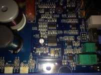
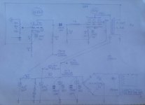
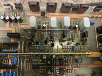
LM3886SMPS vs ICEpower 50ASX2SE

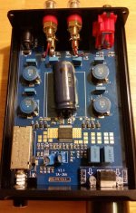
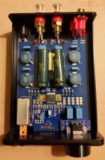
I've run a few searches and can only find one reference of the LM3886SMPS board.

LM3886SMPS | Connex Electronic

LM3886SMPS Stereo Amplifier Module 2x 60W 4 Ohms LM3886T - Audiophonics

All I can find is a picture of a partially installed board:

http://www.jkwynn.co.uk/Pics/LM3886_Lashup.JPG

I am in the process of finishing a set of Alpair 7.3s for my desk set-up and am currently running a 2xTPA3118d2 amp with a 19v 6a power supply.

I was about to pull the trigger on an ICEpower 50ASX2SE and a case from Ghent Audio until I came across the LM3886SMPS. From my understanding, both amplifiers are easy to assemble, the only major difference being that the LM3886 requires a heat sink.


Could anyone offer any advice on which board to purchase, I would greatly appreciate the feedback.

Volume control malfunction - probably NOT the potentiometer

Hello!

I have a Heathkit AR-15 receiver. I recently began having this problem: The volume control does not reduce the volume to zero, on one side only. The right side.
This started after I had the control way up high, because of a Passive Volume Control I inserted after the “Tape Monitor” output and the “Tape Monitor” input. I was using an external volume control to control volume, so the actual volume control on the receiver was turned way up – to the maximum level I figured I’d ever need it. Long story – with a passive volume control I was able to control other devices that were being fed by the Tape Monitor output as well as the receiver itself.
I can’t imagine why that would cause the problem I’m having but it seems like it did. I don’t enough to zero in on what happened when I skewed the volume in that way. I’m stuck at the cause-and-effect level, without the knowledge to go any further.
So the actual problem is, that while the volume in the left channel is reduced to zero by the control, the volume in the right channel hits a plateau and will not go below that. Not even the “balance” control can reduce it.
(NOTE: the Passive Volume Control has been removed and the only volume control being used now, and described here, is the one proper to the AR-15.)
After maybe 20 seconds or so, there is a “null” spot in the rotation of the volume control potentiometer where the volume in the right channel – as well as the volume in the left channel - is almost zero. But that spot is not where the potentiometer is at the zero spot; it’s a little bit after. In other words, at a place where some minimal volume would be expected.
I was willing to let it go at that, since I’d never really need the volume to be that low. So if the receiver powered up at that volume level it wouldn’t be a problem.
The control starts to work as it should at that point and from there on up.
(to re-cap: below a certain point in the Volume Control potentiometer’s trajectory, the right channel sticks at a certain volume and there’s no way to cut it out. Even the balance control has no effect on it. Above that point the volume goes up and down as it should, following the volume control.
BUT if I set the volume control at the above-mentioned “null” spot where both channels are almost zero, and then turn the unit off and back on again, the right channel comes on quite loud. After a short time, well under a minute, the volume begins to drop – back to the almost-zero spot again.
I thought it was the volume control itself so I replaced it. To my dismay, the problem is still there.
In my naïve way of seeing things, I have isolated the 10mfd capacitor that comes after the volume control and before the final two amplifying transistors in the pre-amp and/or the 10 mfd capacitor that intervenes between the pre-amp and the amplifier as possible culprits. My reasoning is that, since capacitors charge, one of those two, or both, capacitors might restrict the volume while charged but, after the unit is turned off it (or they) would discharge and no longer restrict the volume.
I don’t know if this theory has any validity. What I don’t know is how or why a capacitor would be used to restrict volume. So I’m in need of a more knowledgeable opinion. There may well be some other culprit in the current problem, and I am curious to know what it is.
Can someone help me out? I’ve drawn circles around the volume control and the two capacitors I mentioned on the first attached file. The second one is the entire schematic for the AR-15.
Well, that was my plan anyway. Maybe you can help me figure out why this website wouldn't upload my files. I guess th


I’d appreciate someone’s more knowledgeable analysis. Thanks in advance!

bob

Attachments

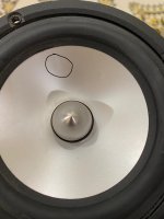
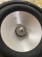
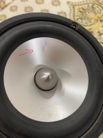
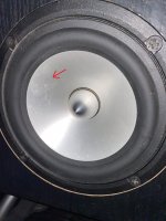
Cone has a small dent/scratch. Audible?

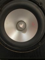
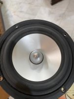
I was in the process of redoing my boxes. And i noticed about 3 of my mids, have very small dents/scratches. Pictures below can be seen.

I was just wondering if this will be audible?

And how can I test the impact of them to see if they are still working as intended to?

I was thinking of measuring all the mids against the one that I know is in perfect form. Should I do it 1" away like with subwoofers? Or should I do it 1 meter?

Attachments

  • WhatsApp Image 2020-05-21 at 5.08.44 PM.jpeg
    WhatsApp Image 2020-05-21 at 5.08.44 PM.jpeg
    197.1 KB · Views: 276
  • WhatsApp Image 2020-05-21 at 5.08.45 PM (1).jpeg
    WhatsApp Image 2020-05-21 at 5.08.45 PM (1).jpeg
    182.8 KB · Views: 268
  • WhatsApp Image 2020-05-21 at 5.08.45 PM.jpeg
    WhatsApp Image 2020-05-21 at 5.08.45 PM.jpeg
    195.3 KB · Views: 359
  • WhatsApp Image 2020-05-21 at 5.08.47 PM (1).jpeg
    WhatsApp Image 2020-05-21 at 5.08.47 PM (1).jpeg
    299.8 KB · Views: 244
  • WhatsApp Image 2020-05-21 at 5.08.49 PM.jpeg
    WhatsApp Image 2020-05-21 at 5.08.49 PM.jpeg
    156 KB · Views: 267
  • WhatsApp Image 2020-05-21 at 5.08.49 PM (1).jpeg
    WhatsApp Image 2020-05-21 at 5.08.49 PM (1).jpeg
    94.8 KB · Views: 114

Who else is gaining weight?

Title says it all. Too much time for cooking and eating and not a whole lot of ladder climbing. Not allowed to play tennis unless it's with someone in your household. Many of the parks are closed, including some dog parks. Very little recreational activities of the interesting kind these days.

It's all eat, drink and be lazy and it's showing up just above my belt.

What's happened to the sa-36a pro - not tpa3118?

Hey all, new to the forum, great info here, even if you're a novice (me).

But, I am a discriminating listener, had done some research here and elsewhere and felt confident that buying a smsl sa-36a pro would be a good choice - with all the high marks given to the tpa3116/3118 chips.

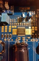
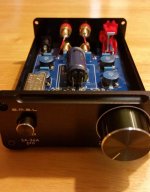
When I received it, the back voltage markings were suspicious (12-15v instead of 12-24v), so I opened it up and here's what I saw: not a tpa3116/3118 but instead a TDA7492PE chip! And seams to be under-powered. I've ordered 3 now from 3 different sellers: Amazon ships and sold by, CrazyEve/Amazon, and an ebay seller sourced in China that seemed legit and shipped very fast (US warehouse probably). The latter is the one I have now. It's strange because the board is printed with sa-36a (not pro) and its NOT using the older ta2020 tripath chip.

What do you think? Is this counterfeit, or SMSL changing the build? How would it measure up against the 2014 2.1 and 2.2 versions of sa-36a pro?

This build looks like a downgrade to me, but I don't know anything, I'm looking for some wordly input from those in the know here. Thanks

2 different units opened up here with slightly different builds.

Attachments

  • sa-36apro4.jpg
    sa-36apro4.jpg
    69.3 KB · Views: 1,373
  • sa-36apro-ex2.jpg
    sa-36apro-ex2.jpg
    66.3 KB · Views: 1,406
  • sa-36apro3.jpg
    sa-36apro3.jpg
    76.3 KB · Views: 1,207
  • sa-36apro2.jpg
    sa-36apro2.jpg
    48.9 KB · Views: 1,199
  • sa-36apro1.jpg
    sa-36apro1.jpg
    36.6 KB · Views: 1,187

Help with se tube amp or kill me!

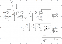
Already for weeks I have been trying to build my first SE tube amp from old soviet TV parts. Tubes are 6P14P on amp and 6N2P on preamp. The amp is working only if I play super mildly and on low level. As soon as I pluck some string heavier a horrible distortion starts. I think I have tried everything - different resistor values, different OPT, different input and pot wiring. Gods are against me! Is there a mistake in schematic? Are the tubes bad? (I have few, all second hand, but from different sources so some of them have to be good.) Probably its just me, but where? Power transformer is 216 Vac on secondaries. B+ is 295 Vdc, B+1 after OPT 260 Vdc, B+ 260Vdc, B+3 = 130 Vdc, B+4= 150 Vdc. Filament Voltage 6.8 V. I have two OPT - one from same TV (measures 485 ohms on primaries, 2,8 ohms secondaries (so WR should be 13:1?)), other one from old radio (WR 23:1).
(The value of R14 is 200 K right now and input has 1 meg resistor that's not shown in schematic).

Can someone help? Thanks in advance.

Attachments

  • Screenshot_2020-05-14 TV amp.png
    Screenshot_2020-05-14 TV amp.png
    31 KB · Views: 268

Apt Holman preamp : hearing an FM station on phono input

Hello,
I use this preamplifier since a little more than a year. It was in the estate of my deceased elder brother.
It had suffered a flaw in the phono preamp, with one channel a lot lower than the other and you helped me solve it. (it was a dead electrolytic capacitor).
I was advised to change all the electrolytic caps in the device but did not proceed because I am afraid to break something.
Anyway, i live near a lot of FM broadcast stations (I'm on the only hill above the city... ) and I've noticed that one station is audible when I listen to a vinyl. If I'm not mistaken, it was not the case before, but I wont bet my life on this...
As the cart has been changed ( an old Grado with a Black2 diamond has given room for an AT VM95E cart), I thought I could play with the input impedance setting and the capacitance adapter switch but to no avail.
So I'm seeking advice here.
Many thanks in advance for your help.
Have a nice day and stay safe !

Can someone help me understand what this circuit does?

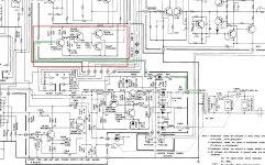
Sherwood S-402CP integrated amp, 1978-80, 35wpc. This amp has pre-out and main-in connections. It does not have a speaker relay. I thought that I had the ability to at least differentiate between signal carrying and power supply, but this circuit has me baffled.


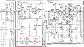
I am referring to a group of four transistors TR304 through TR307, marked in red in the schematics below. I had to split this into two pics to show the entire circuit. The first pic shows that a lead straight off the secondary of the transformer which (I believe) is half-wave rectified and run through a couple resistors, feeds the base of TR304.

Please correct me if any of my assumptions are incorrect. The second pic shows that the outputs of TR306 and TR307 connect to the outputs of the Tone Amp.

What is the purpose of this circuit? Thanks in advance... 🙂

Attachments

  • 402-2m.jpg
    402-2m.jpg
    358.7 KB · Views: 213
  • 402-1m.jpg
    402-1m.jpg
    422.9 KB · Views: 210

3D Tube Files (Pref Blender)

Are there any 3D tube meshes available? I can make envelopes pretty quickly just from an outline. Frank.Pocnet provides plenty of those. Filling the guts though could take a day or two per tube. I just want to plot my circuit while forming layout and the chassis. I don't want a tube used in my project until every connection is bolted down to its terminal block. If I try to jimmy it, I might die from clumsiness.

My Holton amp builds.

Here im gona post some pictures of my Holton build for the last couple of years.
Ounce you tried one, you cant stopp 😱

With the last order im up to 20 modules and one SmartDac.


Today i have Nxv-500R2 monoblocks for the midrange and tweeters.
For the bass system i have ordered another set of Nxv-500R2 modules for another set of monoblocks.
Speakers is Infinity RS1 and dipol bass is H baffel with 4 pc Peerless XLS 12" for each "tower"
Behringer DCX2496 crossover for midrange and bass. Tweeters have passive crossover, but some day some Nxv-200R2 monoblocks will be powering the Emit tweeters.

Sorry for the bad english writing.

Which cables are suitable for Internal Loudspeaker upgrades?

Hi All.

I've been recently engaged with Crossover rejuvenation projects on a number of vintage Loudspeakers.

Part of this is to allow me to build up knowledge and expertise in Loudspeakers.

A member previously advised the use of Jaycar jumbo Speaker cable.
It's fig8 multi strand ofc speaker cable with 12/13 awg per core.
Peeling the two cores apart yields double the length.

Jumbo OFC Fig.8 Speaker Cable - Sold per metre | Jaycar Electronics

I was hoping to get advise as to which cable to use for internal Loudspeaker upgrades.

I don't know either way, but if it's decided internal wiring doesn't have an impact on reproduced sound, then I'd also be looking for things to avoid.
These might include high resistance, poor insulation properties, or other characteristics which might cause issues.
And/or are there wiring conventions such as color etc.

Also, are there cable tests which can be performed?

Not looking for state of the art, but rather best bang for buck solutions.

cheers

Cliff

12A6 Healthkit A7 Amp

here's the post

In a fit of tube fever, I purchased a Healthkit A7 amp that uses a pair of 12A6 beam tetrodes, along with other unusual tubes 5Y3 x1, 12SQ7 x1, 12SN7 x1, 12SL7 x1.

The 12A6 appears to be low power (6 watts in ultralinear) and is very inexpensive ($2-5 each, from what I've seen).

My original idea was to see how they sound for guitar, with the intention of making an inexpensive low-power push-pull guitar amp.

I'm wondering if this migh yield fruit for a guitar amp, or was delerious with tube DIY fever.

Any comments/suggestions/therapy will be greatly appreciated.

12A6 beam tetrode

Heater voltage 12.6V
Heater current 150mA
Max anode voltage 250V
Max screen voltage 250V
Max anode dissipation 7.5W
Max screen dissipation 1.5W

Thermistor removal from crossover rebuild?

Hi.

Having a closer look at my Jamo Crossover.

The negative wires coming from the midrange and tweeter drivers meet together and then pass through 2 circuits on their way to the negative speaker terminal.

The first circuit contains an 18 ohm 5 watt Resistor.

The second circuit (in parallel) contains a Thermistor (PTC C995).

As they can be problematic, I'll be removing the Thermistor.

After removal of the Thermistor do I maintain that second path with a wire, or is the Resistor path enough to complete the circuit?


Thanks

Cliff

EL84 triode wired bias and operating points

Hi all, oprtr back.

I'd like to discuss a concrete example on EL84 operating points in triode vs pentode mode:

Why is it that all of the spec sheets insist that when those babies are triode operated that Rk should be higher and thus the bias lower. Aren't the current swings supposed to be lower and thus safer when running the tubes in class A, triode or not.

I have measured both plate and grid current and dissipation with the tubes cathode biased at 98% and it was perfect. I guess everyone worries about the screen grid, but even at max plate bias the screen was well below the 2W dissipation with no swings.

An externally hosted image should be here but it was not working when we last tested it.


VS

An externally hosted image should be here but it was not working when we last tested it.


What am I missing 😡

OTL Headphone Amplifier / DAC

Hi everyone,

I posted this in the photo thread but later realised that it would be better to have it's own thread in case there is any discussion which would disrupt the photo thread. Just thought I'd share my first amp project, a tube headphone amp with integrated DAC.

The amplifier is based off a well-known OTL amp circuit which utilises 12AU7/ECC82 input & 6080 triodes and is output transformerless (OTL). It should pair nicely with the high input impedance of my my Sennheiser HD6xx headphones. Input options are either switchable line level analogue or USB digital. Digital input is provided via Khadas Tone Board. It currently has GEC CV 2984(6080) and GE 12AU7 tubes installed, these are just what we had easily available at the tim eof building and I had planned to upgrade them. After some research it seems the CV 2984 is fairly well regarded and an upgrade would be quite costly, but i'm interested in any recommendations.

This amp will predominantly reside on my desk at work, the decision was made to integrate a high quality DAC as I have found the sound output of modern office PCs to be quite poor.

I’m very happy with how it turned out. I've attached some pics below but there are more pics and full build documentation on my blog if anyone is interested. OTL Headphone Amplifier / DAC – Jeremy Young Design

Cheers,
Jeremy

An externally hosted image should be here but it was not working when we last tested it.


An externally hosted image should be here but it was not working when we last tested it.


An externally hosted image should be here but it was not working when we last tested it.


baYDxcv.jpg


An externally hosted image should be here but it was not working when we last tested it.


An externally hosted image should be here but it was not working when we last tested it.


An externally hosted image should be here but it was not working when we last tested it.

D'Agostino Relentless Mono Power Amplifier meter

D'Agostino Relentless Mono Power Amplifier | Hi-Fi News

In use you'll regularly see that needle flicking up beyond 300W, but this is 'fake news' - the meters are made to move all the time so that 'users are confident something is going on', admitted Dan, 'fun to look at, but please don't take the numbers too seriously'.
Decorative By Design
Why? Simply put, the early Momentum amplifiers had accurate meters and, with typical real-world outputs being just a few watts for much of the time, the needles were barely moving.

what is this, a toy? and this on:

So this is the first and possibly the only full and independent technical test you will read of the hi-fi world's most luxurious, most powerful, heaviest and costliest amplifier... ever.

:cannotbe:

Can someone recommend me an 4-6 channels amp?

Yo, good morning/evening/night. Im very new to these audio things and I searched for something like "Tri-amped amplifier and just found almost nothing, only wikipedia and desc, but I want to get some good one
I have a set of a 10" sub, a 4" mid and a 6" tweeter (2 of each, stereo sound), so I dont really want something loud asf, I just want the best audio fidelity I can get of them (plan to use for mixing) , I'm whillin to pay at the maximum 100U$D
Also, I am using a very very very very old amplifier, Philco - Hitachi PSR 60, Is sounds pretty good, I used to mix on it so anything 2x better than him (doesnt need to be loud as him, I use him at 1-5 volume (from 1 to 10) also, my speakers are 8ohms
Thank you for the attention 🙂

please help a beginner with some questions

Hello everyone, :wave2:

I am new to diy audio and have been researching and dreaming of speaker design for quite a while and now the time has come for me to make my first speaker and would love some help and answers from the diyaudio community. I have decided on a closed box, 2 way design to keep things nice and easy for my first attempt. I've decided on the drivers, the tweeter being a vifa XT25BG60-04 and a SB13PFC25-04 for the mid/sub I have attached the spec sheets below. My reasons for selecting these drivers was 1. Budget 2.i had heard good things about them mainly internet reviews and comments and 3. They seem a reasonable match for a crossover for a two way (at 2khz). as a newbie i would love to hear any opinions on this.

The main questions I have concerning the drivers is power ratings. The woofer is rated at 40w (rated power handling) and the tweeter is rated at 100w (rated noise power). Are these the same? And if so is the difference in the power rating a problem?.

The other power rating questions I have is to do with crossover components. I have designed the crossover and all its different values. But i'm a bit confused by the power rating of components like resistors etc. should the components be rated the same as the drivers eg: 40w for woofer and 100w for tweeter?. Or is it the same wattage for the whole crossover? Does anyone know of any guides for this?

Cheers everyone hope to hear from you all soon.:up:

Attachments

NOS Nakamichi DAC-101 2X TDA1541A-S1

Hello! I have an old Nakamichi DAC-101 that i would like to run in NOS. The digital filter YM3414 (4 or 8times OS) split the I2s signal to one left and one right . The left signal comes to the dac TDA1541A-S1 like one "left normall" and one "left inverted". The right signal goes to it's dac in the same way as the left do. I need to find a device that can replace the digital filter. I only want the I2s signal to be splited in left and right without filtering or OS. I send the schematic for you people to see.

Attachments

Op Amp (OPA134) driven Power Amplifier

Hello!

Op-Amps would be perfect to drive and control power amplifiers
if it wasn't for one thing:
- they work at too low voltage when it comes to higher power.

With the method I will show you, you can drive a power amp
even from an opamp working from +5/-5 Volt supply.

First, opamps can often put out 20-40 mA.
OPA134, which I have used for my SPICE, puts out 35-40 mA.
This is more than enough to drive one power output stage.
A triple Darlington needs no more than like 0.1 mA for plenty of Watt out.
One ordinary Darlington (driver + power transistor)
should do well on a couple of mA. Maybe max 5 mA in worst case.

This tells us, that there is no need to amplify the current from Op Amp.
We can let the output current, as it is, drive the power amplifier output.


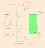
If you look at my diagram, you see the opamp output is split in 2 halves
and via foldback transistors fed to the output.
The blue lines show the path.

I have done SPICE for 100 W/8 Ohm 200W/4 Ohm with great results and performance.
OPA134 is good enough for this job.
I think you should have a look att this method if you are intesrested.

Regards Lineup

Attachments

  • opamp_drive_poweramp.png
    opamp_drive_poweramp.png
    13.1 KB · Views: 2,958

Troels Seas 5"

First off a thank you to all the hobbyist who contribute to the diy HiFi community. I was hoping you guys may be able to shed some light on a question I have pertaining to Troels 5" Seas design using the the 22TAF/G tweeter SEAS 5INCH . I have the CA15RLY driver but not the tweeter. What I do have is the Seas 19TFF1(H737) and the Seas 27TFFC(H0881) tweeters. I am sure by now you know my question. What if any mods would be recommended to the crossover to use one or the other? I do not have the crossover skills some on this website have. I can build cabinets, wire up crossovers and put everything together. Just do not have the crossover design skills. I am more of a kit builder. This design will be built to Troels specs except for the tweeter mod in the crossover. Thank you for any help you can give me

purpose of 6J6 tube in amp circuit

Hi,

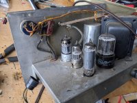
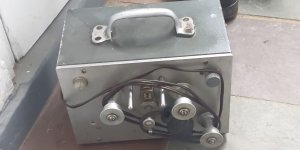
I found a box that that seems to be part of a moviola editing machine or 16mm transfer system. Inside the box is an amp consisting of a 12AX7 , then a 6J6 and a single 6AQ5A power amp.

Both sides of the 12AX7 are being used, before and after the volume pot, but only 1 side of the 6J6, which then goes in to the grid of the 6AQ5A.

The input of the amp is a monophonic tape head going straight in to the grid of the 12AX7 and the output is to a 49.7:1 transformer and 4 ohm speaker. There are no controls other than the volume/power switch.

Could anyone suggest what the purpose of the 6J6 could be?

Thanks

Attachments

  • IMG_20200424_165634.jpg
    IMG_20200424_165634.jpg
    993.1 KB · Views: 658
  • IMG-20200424-WA0004.jpg
    IMG-20200424-WA0004.jpg
    75.4 KB · Views: 454

customizing a potentiometer

the schematic is attached below for further examination

i have a 10k log pot

i need it to behave as 0-33k from wiper to out
and 0-220k from wiper to ground

if i add a 68k resistors in series with the output lug and then parallel the end of it with the wiper using another 68k resistor

and placing a 220k series resistor in the ground lug then strapping in parallel the exit with the wiper

then will it behave the way i described?

Attachments

  • 20200522_080333.jpg
    20200522_080333.jpg
    344 KB · Views: 170

Thinking about toroidy.pl 6B4G PP build

Hi Everyone,

I've built a lot of single ended gear using el84's, 2A3's, and 6B4G's. and I've owned/repaired/modded single ended gear using 6V6's, 6L6's, EL34's, KT88's, and 300B's. I've owned a few PP using 6L6's, EL34's, and EL84's.

Overall I've enjoyed the sound of the SE el84's and 2A3/6B4G's the most but I am starting to miss the bottom end and being able to use a variety of speakers. I have a bit of money at the moment I can use for audio and I'm debating what I should pursue.

The reason I've been thinking about a 6B4G PP is because I've heard a lot of people, that I respect their opinion, say they've really enjoyed them, even though it's PP they still seem to have a pretty high 2nd harmonic, it would give me some extra power to play with, better bottom end performance since it's PP. The down side would be the added expenses of 4 output tubes, and possibly making the circuit more complex by going with CCS and DC heater filaments. (with high efficiency speakers I really like having a very low noise floor, my el84 amp is 30 Db if I'm remembering correctly)

One other project I'm considering is modding my el84 monoblocks to run with either el84's or 6B4G's and then using my minidsp as a crossover with subs. I have James Audio outputs in it so I have multiple taps and could run both tubes at the their preferred output tap. I just know from past experience I would have to go DC for the 6B4G's filaments. Also I'm not sure if it's possible to have one driver stage that would work equally well for both tubes or if I would have to have to do separate driver stages.

Currently speaker wise my tube amps drive either my econowaved ElectroVoice Aristocrats or my Klipsch RP600's. I was gifted some custom speakers by a friend that have 21" woofers and enormous JBL mid horns but, one of the woofer's voice coils is rubbing 🙁 so they've just been sitting, also they're enormous and I don't really have the space to set them up properly. My only other speakers are my McIntosh XR 1051, after I recapped them I really enjoyed them (they mate very well with a Citation 16 I rebuilt from the ground up).

Also part of me thinks I'm a little insane for starting another audio project when I have about 6 other audio projects I have parts for but, the idea of building my first PP and getting 6B4G sound with more power and bottom end is an exciting thought.

The reason I was thinking about toroidy's outputs is because I like the idea of an extended frequency response and people that use them seem to be very happy with them. I do know that I would have to be careful of balancing the DC with a PP so I was thinking about using CCS to keep it balanced. In the end even if I don't go for the PP 6B4G I think I would still pick up a SE output from them just to play with. I am curious if I could squeeze more bottom end out of a SE el84 with one of their OT.

As a side note, that I might make another thread about is, my 6336a SET amp. I've noticed when comparing it to my other amps the mid-range seems muffled and I'm wondering if it's because of the driver stage (it's only using half of a 6SL7) or maybe that's just the sound of the 6336a? I'm wondering if I should mod it or just move onto something else.

Sorry for the long post there's just a bunch of factors effecting this decision for me.

As always any thoughts, ideas, input, is greatly appreciated:up:

Yamaha M50 looking for schematics, service manual incomplete.

Hello,

i got a Yamaha M50 on the healing bench, but i cannot find a schematic for it.


One of the channel the 2SC2581 are shorted and the 0,33 ohm resistors are open. not sure if anything else is blown, was about to check with the schematic on hand before going in blind.


elektrotanya and hifiengine provides a service manual which mentions schematics on page 14.. but the scans i found only go to page 11.


Does anyone know a source for a full service manual or have one?

ive seen schematics on radiomuseum but you gotta apply for paid membership to see them...


thanks in advance!

Hickok 539A meter replacement

Hello all,
I have a Hickok 539A tube tester with a busted transconductance meter. Exact replacements seem to be very difficult to find, but I’m thinking of replacing the meter with one from another Hickok tester, if I can find one, and swap in the scale from the original meter. This is providing the new meter has the same physical dimensions as the original of course, also as far as the scale is concerned.
Do any of you happen to know of Hickok meters that would fit? And still have the original outer appearance? The manual unfortunately doesn’t mention which type of meter was used. Judging from pictures, the 532 or 600 seem to look alike to me, but I’m not sure.
The replacement meter will probably be less sensitive, but that could be compensated for with a suitable opamp circuit, so that wouldn’t be a dealbreaker.
I’m looking forward to hearing if you have any info on this.
Thanks...

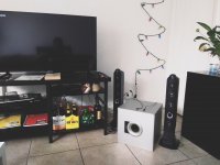
TV + Subwoofer + Speakers - Can we make it work??

Hello everyone,

sorry if I ask silly questions. I'm new to this stuff and English is not my native language what makes it a bit more complicated.

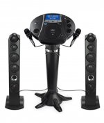
The bottom line is can I make it work? I want to connect Speakers and subwoofer to Samsung Smart TV.

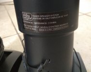
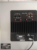
1) I got those speakers without middle part. Originally they were for karaoke system with two mics. That's why each speaker has mono 1/8 (3.5mm) jack (see on pic).

2) I got subwoofer. Check details on the picture.

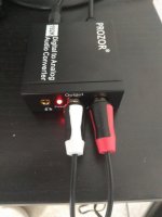
3) I got adapter to have connection from TV to speakers through optical output (see on pic).

The problems are:
1) Speakers have 3.5 jacks but subwoofer doesn't.
2) Speakers have 3 ohm.
3) Maybe more problems, let me know))

Can any of you see how it might work? Should I buy something in between? Cut jacks and insert to subwoofer (high level output)?
Or those won't work together and I should quit?

I will be thankful for any ideas!!!

Thank you!!!

Attachments

  • 1.jpg
    1.jpg
    503.7 KB · Views: 78
  • 2.jpg
    2.jpg
    392.6 KB · Views: 83
  • 3.jpg
    3.jpg
    381.6 KB · Views: 72
  • 4.jpg
    4.jpg
    418.7 KB · Views: 84
  • 5.jpg
    5.jpg
    375.4 KB · Views: 81
  • 6.jpg
    6.jpg
    53.2 KB · Views: 70

LXmini: i see an issue

I'm a big fan of Linkwitz. Just now some commercial speakers are beginning to play with solutions to the cardioid dispersion question.

Here is my hangup: I understand that the omnidirectional nature of the horizontal driver combined with the dipole creates a cardioid response. What I don't understand is that they are crossed over at 700hz and as such will only exhibit cardioid dispersion patterns close to the crossover frequency. Above the x-over being a pure dipole and below an omni. I'd imagine one would have to run two full range drivers in that same physical config crossed over to a woofer in order to gain cardioid dispersion characteristics throughout the frequency range above woofer crossover.

Am I missing something?

Nice deal on Tektronix P6230 Var Bias Probe

Sweet deal on Nice TEKTRONIX P6230 Variable Bias /Offset Probe
Seller still has 2 left out of 4.

I'm stoked about mine, been looking for long time. Looks .like new, looks unused. Works like new.
These are from/tagged IBM NY, 'LOAN POOL Equipment'

Seller wantled 47, he jumped on my offer of $40. Free Ship
Initially listed $385. way back in the day. Note the probe power plug requirement. All of accessories and orig vinyl bag.

Used Tektronix P6230 Variable Bias Offset Probe 10X 450Ω 1.5GHz NICE M4 | eBay

From my Goo drive pictures
P6230 - Google Drive

Philips CD610 disc spins backwards

Hi there

New on the table today is a Philips CD610 CDM-4/19.

Lens cleaned, disc spins jerky backwards when inserted - fraction of a revolution. Not reading TOC of a factory CD, shows ERROR in display.

Had it apart, cleaned all the connectors on the PCB, back together and same thing.
From the side a laser can be observed. The laser head is bobbing up and down.

It's late at night here so I've not been over it with an oscilloscope or DMM yet.

I've got the SM in English, just wondering if there's anything I'm missing?

I've also had a peek at the solder joints and can't see anything outstandingly bad. Nothing observed abnormal.

In the last week I've recapped an older CD460 successfully, also rolling op-amps too.
I noted that none of the electrolytic capacitors were off-value or with a high ESR, so I'm erring on the cautious side and not thinking it's them, as it's a newer model by 5 years or so.

Anyhoo...any pointers would be welcomed!

Cheers

GB

Hello from Amsterdam, Netherlands

Hi there,


I am a software developer living in Amsterdam since 2014. Originally from Argentina. I also lived in Madrid, Spain for a long time.

I have some experience with digital and analog electronics, and lately have been busy with a few audio-related projects. I actually registered in diyAudio more than 6 years ago but never posted. Better late than never!:snail:

I am in the process of building a class A amp, and if I can get a pair of those Jensen transformers, it's going to be based on Nelson Pass' F6 design.

Regards,
Iván

Is this design correct?

First, I would like to thank the members of the forum. I have benefited a lot from them. This is the first design I will make and I want to know whether everything is fine in my project or there are notes on it.
Project components
Drive ...
Peerless by Tymphany 835017 12 "Aluminum Cone XXLS Subwoofer
Amplifier ...
Dayton Audio SPA250DSP 250W Subwoofer Plate Amplifier with DSP
Tube ...
Precision Port 4 "Flared Speaker Cabinet Port Tube Kit
Bassbox Pro was developed In the attachment case pictures....
p_1593o7iwy1.jpg
[/url][/IMG]
p_1593whft02.jpg
[/url][/IMG]
p_159367bvr3.jpg
[/url][/IMG]

First Subwoofer - What should I pay attention to?

Dear DIY Audio,

I am thinking about building my first subwoofer this year, and I don't know where to start.

I was wondering what the are most important factors to pay attention to. So far I believe I have to consider:

1. It will be in an apartment bedroom (not too loud, not too big, wall to wall carpet)
2. Should I design it to be placed in the corner like a REL subwoofer to take advantage of the long axis of the room?

What other parameters or considerations should I worry about? What shouldn't I worry about?

I am nervous and excited to start! I'm a couple years out of engineering school (EE) but I haven't touched this space before, so any help would be appreciated!

Thank you so much!

Voltage regulator (LM317, LM7805) decoupling capacitors

I'm "refreshing" an Adcom GDA-600 DAC and would like some tips on the PSU section. The unit is now 27 years old and I'll be replacing the caps in the power supply.
I'll be using Panasonic FC for the main filter caps.

The decoupling capacitors for the voltage regulators used here are Nichicon VX (standard) 10uF 35V and 0.1uF MLCC (not sure which type) for the LM317 and LM337 adjustment pins.

Most of the components in this unit look to be very solid choices but in this case it does seem to be economic as these caps are used throughout for various duties.

I've read through many LM7805 and LM317 datasheets but since some are 40 years old, perhaps with changes in capacitor technology and availability, better choices can be made.

The schematic is attached with capacitors marked.
Red -- output decoupling caps
Green -- input decoupling caps for the regulators that are used by the PCM63-P DAC chip
Blue -- 0.1uF MLCC for the adjustment pins. (datasheets recommend 10uF-20uF here)

I would appreciate recommendations for each of these positions. As of now, I only chose 10uF solid tantalum for the output caps based on their usage in previous projects with the LM7805.

P.S. I'm replacing the LM317/LM337 with LT317AT/LT337AT which have slightly better specs.

Attachments

  • GDA600 PSU.PNG
    GDA600 PSU.PNG
    119.7 KB · Views: 630

DIY line output transformer

Lately i am experimenting with various diy opts for use as line output transformers intented to be driven by trioded pentodes with Rp from 2k to 5k. My target is something around 5:1 and the best banwidth possible. I am able to wind any type and got alot of time and experience. I have tried so far 2p-2s 3p-3s and also split bobin 1p-2s + 1p-2s and 3p-3s+3p-3s. All of these with no luck yet as resonances seem to fall inside the audio band or near it. Mostly i use around 3000 to 4500 primaries with paper interlayer insulation and sized EI75 and EI84 grain oriented cores. Any help would be appreciated.

Hello from Spain

I'm Pedro from Madrid.

I have interests in DIY electronics solid state, like JLH and and MOSFET amplifiers, and digital sound projects.

I'm a modest builder, though I'm now working in a music-box with Raspberry 3B+, for now it has a big linear power supply, a cheap chinese DAC (PCM5122 based), infrared remote control, and USB external ports, and auxiliary USB for powering external hardisks and external DVD.

My next step is add a cheap 3,5" color LCD screen, a wheel controller and set of buttons to control it.

Later I have plans to buy a cheap USB radio to add DAB tuner.

I'm waiting for heatsinks and several kits to build a JLH amplifier.I have already made a little linear power supply for JLH1969 with 27 V dual rail and 2,5 A.

Hello This is Chris

Hi
My Name is Chris and I'm a long time member of this forum..
I'm living in BERN, Capital City of Switzerland.
Bad as it is, I was just reading here once a while. and this since 2012 the day I registered here.

DIYAudio kept my username secure and I my password..
If there wouldn't be a person who asked me if I would place some of my Builds here, I might wouldn't write this here today.

Now, since I gave my promise to that person, I will keep my promise.
I started building Amps back in 1974 *I was 22 that time*, so this shows you my Age, which is about the same age the person who asked me.. I will not name this person but the person is also a senior member here.

Myself, studied Car Engine Engineer in Swiss from 1968 - 1972.
Have seen Jime Hendrix live in Concert, Led Zeppelin, Clapton, Deep Purple, Pink Floyd, Roger Waters and many other Groups in that time and also in the last 18 Years.

Moved to Asia in 1974 till 2002, when I returned to swiss inclusive my Family..

As I couldn't work on my profession in Asia, I ordered some Electronics Books from Switzerland and read them at least ten times. I was very eager to learn that stuff.. But I was young and travelling all throughout Asia, just working when I needed Money to support me living expenses.. In 1990 I met my Wife, and then we seddled down in Bangkok. In the meantime I learned to read write speak Thai, almost as good as a Thai..

1975 I build my first Amplifier * Pictures will follow soon* it was an Kit Amp Class AB 100 WATT this amp still works until today,.

1976 I found myself digging very deep into Amplifiers but in fact I didn't had a big clue yet, so I started to read Electronics booklets in english and Thai to get more knowledge..there it was that I found a schematic of a Class A Amplfier which Input device was a UA 741 * one of the worst IC's * which is still sold till today..

This was three stage Amp as predriver was a SB649 * Hitachi* may one of the best Low Voltage transistors that time *UCE = 160V Imax 3Amp and Ptot 3 Watts. Then Drive was a SD669 this is complimetary to SB649..
Output were two SC1047. No current source, but instead they used a 220 Ohm 10Watt Resistor with a 2200 UF 50 volts cpapcitor to get the Current working while crossing by a Reversed diode between the output Transistors.

So I build that amplifier and believe me I gave my best but this Cirquit never worked as it was supposed too.

So after a few weeks I managed to get it working, removing the 220 Ohm Resistor with another SC1047 as Current Source and removed that Capacitor as well.

Exchanged this diode with a HIGSPEED Diode and later with a SB817 which is the comlimentary Transistor to SC1047. That time I had only a Sanwa Analog Multimeter, no Scope nothing. But I got that too work and with a decent sound. I did build that in the early 90'ies again and went to get a computer read out it was quit good, but in the meantime I owned a Hameg Osciloscope 20 MHZ. I also will place that here.

Since then I always tried to build Class A Amplifiers, also owned a Threshold second hand, and still Own a Forte Audio A 100, couldnt afford a new one used them with Marantz Speakers Model HD880. These were American Made Marantz 4 way. Beautiful sound.

2002 We returned to Swiss, so I couldn't move all my sound Equippment to Swiss. Now I started over again to build Amps. Then I saw a Class a Cirquit of a Australien guy Named Scott Elliot, he is the counterpart to Nelson Pass.. Bot of them are Geniuses when it comes to Amplifiers..(Check out that Picture below or use the link.)

Anyway he created a Amp called DOZ * as he told me * this was the Amp he fought the ZEN amp of Nelson Pass. The meaning of DoZ is = Death of Zen.

Here you will find a link to this Amplifier..

Death of Zen - A new Class-A power amp

I also build this amplifier but before I build it, I modified the Schematic to dual Rail Voltages meaning +- Rail with commone Ground.Also meaning rearranging almost the whole cirquit.

Changed Transistors to MJL4281

Added a Servo Control and again removed any pieces in my sight not needed. Like a couple capacitors. Added a Transistor between Input and Drive. and several other things. then when it was finished I send a mail to Scott and showed him the work. and when I talk about work, then I mean all of it. No Secrets kepts. This amp * the modified version * which is quite different from the original works fantastic. I build 7 Version of this one, latest was in 2017 and has only the Input Section which still shows the Tremendous knowledge of Scott Elliot in designing Amps..

For Scott and also Pass, these two guys are unsurpassed and are the " Gurus" = MASTERS of Amplifiers, when it comes to Amp developement. Here my thanks to both of them for their absolut best work there is out there.

If in any of the upcoming Artwork, Schematics is others People Work is included then it will be notified and the credit goes to owner.. Even the Amp design was made by my, the IDEA is the groundlayer for this and this should be in any way and Matter given to its owner..
By the way: I building amps for FUN not for a living.

This Year I created a few different Schematics of Class A. Things which actually shouldn't work but they do work..

I will place schematics, Spice Work, Layouts and the build up of every Amp I created or Modified. I do not copy paste Amps. But may taking advantage of the Idea of these two Masters they had in the past, and would fit my thoughts of Amps. there is barly enough to get your own design.. there are only three ways to create an AMP..

Thanks

Regards Chris Hess
Anything inherently wrong with this design?

I have cobbled together and modified a few headphone amp designs that I found on the internet to utilize parts that I have on hand. I have built a working single-channel prototype and it seems to work well with an extreme amount of gain into my cheapo standard impedance headphones. I was hoping that someone a bit more well versed in tube amp theory could tell me if anything is inherently wrong here. My goal was to create a cheap but functional design. Total bill of materials not including an enclosure should be ~$100. B+ is 230vdc but I still get an acceptable amount of gain at 120v through a regular isolation transformer. I didn't change any component values for the lower voltage. I just changed power supplies. The output transformer is a Dukane line matching transformer. Primary~15k to an 8 ohm secondary. This isn't specifically what it is designed for but they cost $4 each and are rated to 4 watts. The sound isn't too shabby either. The design would use three 12at7 tubes. 12au7s also work, but have less gain. Still way more than necessary at the 230v B+ though. I haven't tried any other tubes in it. Power supply is just a typical transformer/ bridge rectifier/ pi filter setup.
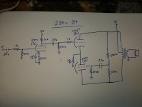
Anyway, sorry for the crudity of my lovely artwork and I appreciate the help.

Attachments

  • 20200426_203359.jpg
    20200426_203359.jpg
    573.8 KB · Views: 485

Compression driver with a highest sensitivity available

Hi guys

Please advise on the matter as in the title. I am looking for a compression driver + horn combination with a sensitivity of at least 110dB, but in the 2-15 kHz band. At frequencies close to the lower limit, the sensitivity may be arbitrarily higher, but it is important that it does not fall below 110 dB in the entire indicated band. I deliberately wrote sensitivity - nominal impedance is irrelevant, and a low value increases the sensitivity. Impedance at the level of 4 Ohms would solve this problem and many currently available models would meet the indicated condition - the problem is that they are not available in the 4 Ohm version...Of course I'm looking for a hi-fi/hi-end driver, not a fire sirens ;-).
Thanks in advance.

Pearl layout - how to organise things to avoid noise

I'm drawing a new layout for pearl because I have some slightly different parts and I enjoy the process of reading a schematic, make the layout and etch it my self.
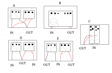
But since I am redoing it completely, I am trying to figure out if I should change the layout slightly.

The input section is according to the article and threads very sensitive to noise. If the two boards are in the same case, the input of one of the channels will be very close to the output and voltage regulater of the other - is that a problem? Would it be a good idea mirror the channels so the two input sections can be together or far apart?
I'm making it for someone I know and I think he will prefer, if he doesn't have to split two many cables, so Right and Left should be placed close to each other for input and output if possible.

I have made some suggestions and attached primitive sketches. What do you guys think, should I try something new or try to get as close as possible to Waynes layout?

Attachments

  • pearlcase.png
    pearlcase.png
    5.9 KB · Views: 2,746

  • Locked
Bose 901 II reproduction... the right way

I know nothing about putting speakers together. This is my first time. Thanks for understanding my incorrect use of terminology and stupid ideas.

I have fallen in love with the Bose 901 II design aesthetic. I would like to build my own but with a more conventional driver setup. I think I like the idea of 89% of the sound coming from the back, and 11% coming from the front since I can only afford cheap drivers. This ratio doesn’t need to be perfect.

How would you setup speakers to do something like that? I assume you would do a combination of sub/mid/tweeter. Which go on front and which on back keeping in mind the back has 2 panels and should be balanced.

I don’t know that I need specific driver recommendations at this point (but happy to hear them). I’m just looking for direction and what to look for.

Bluenote Koala No Power

Hi, i currently have a bluenote koala cd player. When i plugged it, ther eis no power to the device but there is a whining noise coming from the power supply/cd drive area. On closer inspection, one of the capacitor on the power supply is bulging. Do anyone know what is the cause of the problem? Or do anyone have the service manual for the bluenote koala? Thanks!

A tube amp for an odd beast

Hello and thank you for stopping by. I need to throw this out there, and start getingt to it.

I'm gearing up for my 3rd tube amp build, but, this one may stand to be something different from my previous builds - I've built a Fender 40 watt and a 20 watt 6V6 Marshall plexi. I'm an electronic technician pretty much by trade so fortunately, these builds went well and I use the Fender as my gigging amp.

I need to build a third amp for an instrument I made. On first sight, this intrument looks like a walnut Stratocaster with elaborate brass inlays and one single pickup, a humbucker in the neck position. This "guitar" will never be picked, plucked nor strummed. It is a fretless that I made strictly for use with an ebow (electronic bow). It is a pure, singing melody instrument who's lyrical expression is far close to a cello or violin than any guitar you would ever hear. It is my big, 10 pound electric violin/cello that looks oddly like a Fender Stratocaster. Primarily I've been using it straight through my DI - micpreamps - stereo FX processor - D/A converter into recording software. I'm fairly convinced that it would benifit from an amp that has a strong Hi Fi element(s) to it. It can sound good through a typical clean guitar tube amp but sounds a bit strident or mushy. a little of that is OK but it lacks a more pristine quality that is heard though my relatively hi-end home studio front end.

I'd like to use a pair of KT88's for the power section. The idea of having good headroom at moderate stage volume is attractive, and plus, I just like something about those tubes, even the way they look.
The option for UL also is something that interest me for this project. and if for some reason, I preferred straight pentode, I'd still have the option.
I build a "tube designed station" out of an old Bogner amp so, I'm in a good place to try different topologies as I go.

Strangly enough, this "guitar" used with the Ebow, volume pot full up yields an output of nearly 3 volts at maximum. This is just about line level and a very high output compared to the typical 250mV of a typical electric guitar. So right there, It would be easy to push every stage of a typical guitar tube amp into saturation (which is the opposite of what this will need).

In my recent looking around for alternatives I found those Dynaco Hi Fi amps interesting, that perhaps they may be a good start to hear what this strange instrument would sound like though a more Hi Fi tube amp.
What would your first inclination be for an instrument with 15k ohm @ 2-3volt output be if you wanted it big, rich and clean?
I figured it wouldn't be too much to ask for 60-70 watts from a pair of KT88's in UL.
Thanks muchly for your time,
Phil D

Help for PCM1704 Delay Circuits and Other

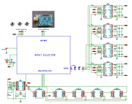
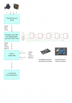
I try to make a NOS balanced dac with 4xPCM1704 and JLSound I2SOver module.Before to draw layout and PCB boards i need help and some advice from members if it possible.My circuit like that block diagram.My questions are ;

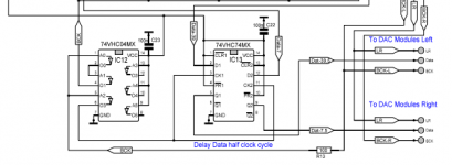
  1. Do i have to add a delay data half clock cycle circuit after my buffer and 7 bit delay like DDDAC ? It confused me.
  2. Do i need to use a SRC4192 after WM8804? Or my diagram is enough to get coax and optical inputs?
  3. According to members experience, NOS or DF1706 Oversampling.Which one should I prefer?
Best Regards

Attachments

  • DAC.png
    DAC.png
    139.2 KB · Views: 320
  • DAC.pdf
    DAC.pdf
    571.6 KB · Views: 102
  • DAC1704 Circuit.png
    DAC1704 Circuit.png
    69.2 KB · Views: 345
  • dddac.png
    dddac.png
    30.4 KB · Views: 322
  • DAC1704circuit.pdf
    DAC1704circuit.pdf
    844.6 KB · Views: 125

Missing PCB pad.

Just replacing some damaged caps in an Audiolab 8200CDQ. This is the second time this has been done as I have power supply issues where I live. The first recap was done by an IAG certified tech. When I unsoldered the caps I noticed to of the pads on the underside of the board are missing. They are intact on the surface. Can I still solder to these? Just use more solder so it runs through the bottom to the surface pads? What’re your thoughts?

Attachments

  • 17221376-012A-4CCC-AC75-8D9F81180994.jpg
    17221376-012A-4CCC-AC75-8D9F81180994.jpg
    613.2 KB · Views: 168

Stromberg Carlson ASP-60 out of phase transformers

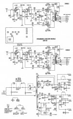
Can someone explain to me the reason for this stereo amplifier to wire the output transformers out of phase from each other? The primaries are flipped from each other and the feedback windings are also flipped from each other but the speaker taps are wired in phase so the outputs are essentially out of phase from each other if you hook up your speakers correctly. I don't believe it's a drawing error since there's an amp on eBay that someone wrote a warning on the bottom plate about its reverse phase so it is wired correctly according to schematic. Very strange. This is also the second half of an integrated amp (full pdf schematic) section but can be used independently. But in the preamp section there's no phase switching on either channel. Head scratching.... 😕 :scratch2:

Any thoughts?

Attachments

  • Stromberg_ASP-60_schem_1600X2600.jpg
    Stromberg_ASP-60_schem_1600X2600.jpg
    472.8 KB · Views: 238

Is it ok to have metal parts close to esl diaphragm?

Hi,

I started a new (fourth) ESL DIY project last winter. This will be the first one that has an integrated damping screen. I glued the damping screen on the wooden frame (which holds the stator wires), and on top of the screen I put the pvc spacers. The glue penetrates through the damping screen (mesh) and this bonds to the pvc spacers laying on top of the damping screen.

It seems that the damping screen is glued well to the wood, but the pvc spacers are a little loose. This is not a big problem as both stators (front and rear) will be bolted together, but I want the pvc spacers to be firmly attached to the frame. So I came up with the idea of using screws to attach the pvc spacers to the wooden frame (with the damping screen in between). I would think this is ok as there is no electrical connection between the screws and the diaphragm: the screws will lay a little lower "in" the pvc spacers and I will only apply conductive coating on the moving parts of the diaphragm (not where it overlaps the pvc spacers). I will use a small copper tape to connect to the bias power supply, but this won't overlap / touch the screws (and bolts) either. As in previous models there were not probems using bolts going through the stators and pvc spacers, I would think it is ok to use these extra screws to attach the spacers to the wooden frame?

I hope I explained my situation clearly enough...

Offset 20mv Hiraga PrePre

Years ago I bought a Hiraga PrePre from 404 Not Found

I've used it before and was able to zero the offset. However, this time I am using a battery bank (to charge phones) and the voltage is 5.18VDC. When powered up I cant get the offset lower than about 20mv. Would this fry my coils of my Denon DL103 cartridge?

Any tips how to get a lower mv? Do I need to install a different pot or could I do it a different way? I have also noticed that the offset voltage goes up when I remove the battery bank. Is this normal? (voltage might go up to several volts)

Rear fill speakers and signal done the right way

I have now gotten my hands on a Helix p-DSP cheaply and a SPL-Dynamics ice-150.4 amp for my front speakers. I plan on making my Alpine SPR-50c speakers active. I have a kicker DX125.2 laying around and have planned on adding rear speakers.

Now I have heard from all the audiophiles to not bother with rear speakers, but I found the right way to do it. Now I don't know how to implement it.

First the rears should be band-pass eq:ed from +-200hz to +-7khz and 20+ms of delay should be added. Then the right signal should be added out of phase to the left signal and vise versa. This should make it so that they don't play any centered sounds like vocals, that exist in both L and R signals. This is pretty much what the early Dolby Pro Logic processing did.

The problem is, how do I do this. Only the newer Helix DSP processors seem to have this function in the input mixer. And the other way is to use balanced signals and just cross the signal wires. But I don't have either, to my knowledge.

Would there be an easy way to implement something like this? And if so, should I use coaxials or midbass speakers in my rear deck?

Ground Zero GZRA 1.1650D class D IC to recognize ?!?

Hello again guys !

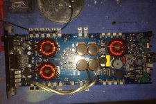
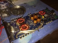
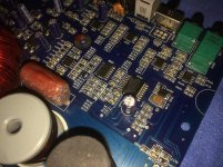
Ground Zero GZRA 1.1650D - blown output, no gate drive even if a feed a strong RCA signal.

Voltages are OK at pads. PS section is OKAY.

Have to change to IC-U509, as this one gives out the gate drive directly to IRFB4227 - but it's scratched. This is the first time i ever see this chip used in class D.
U 108 is 74HC02D.

Can anybody give a clue ?

Pictures attached.

Attachments

  • 0.jpg
    0.jpg
    319.3 KB · Views: 218
  • 1.jpg
    1.jpg
    368.8 KB · Views: 236
  • 2.jpg
    2.jpg
    379.2 KB · Views: 203
  • 3.jpg
    3.jpg
    375.8 KB · Views: 237

Power Supply switching frequency - what?

I greet all the members of the forum.
I apologize if maybe I posted in the wrong section, but in fact, the purpose is to fix a power supply of a car audio amplifier, so it seems right.
I'd like to understand one thing.
When we speak of "oscillating frequency of a switching power supply" do we speak of the frequency that is read on the gate of the mosfets, or of the triangular one (sawtooth) present on pin 5 of the TL494 or pin 6 of SG2525?

POLK LS-70 mods

Hey gang,

I recently picked up a set of these for a friend looking to upgrade from his small B&W standmounts on the cheap.

http://www.hifi-classic.net/review/polk-audio-ls-70-118.html

I was able to fix a voice coil rubbing issue by turning the offending driver around 180, worked like a charm, however I noticed on doing so that there was no stuffing behind the driver?
This is kind of a 2.5 way design? The driver I removed was just below the tweeter, plenty of stuffing between it and the lower woofer but none behind it?
I might try some foam I have around but I'm curious to know if this omission had a reason behind it? (pun intended)

Old 80's Panasonic Boombox

I picked this up a few days ago: PanasonicBoombox.jpg - Google Drive

It's a Panasonic RX 5085. Sounds surprisingly decent, maybe a little light on bass, but I don't mind. Contrary to my username, I don't know anything about these boxes. 🙂 I did have a few questions though, so enlighten me.

1. How does the "ambiance" mode on this thing actually work? There's mono, stereo, and ambiance. Flipping it to that mode seems to artificially expand the sound stage and create this fake "surround sound" effect. I don't really like it because it makes the music sound weird, but I am curious, how does it actually modify the signal to achieve this effect?

2. What type of enclosure do the drivers sit in? From what I could tell, there's no ports, but the design looks too leaky to be a sealed enclosure. Does this mean it's open baffle like most car speakers?

3. I was planning to open and clean everything up inside. Will adding a bit of polyfill or other dampening material inside the enclosure improve sound quality and bass extension? Or will this cause other problems I'm not aware of?

4. Do these boomboxes have the same issue with the worn foam surrounds as bookshelf speakers at the time? Will I have to replace the surrounds soon? Or are they rubber or something like most of the modern stuff?

Orion Hcca 5000 ESP indicator “On”

Hi.

I am working with an orion hcca 5000. it is the first time that I work with this brand and the ESP protection system. This amplifier when connecting remotely, only lights the POWER led and 3 pulses the ESP led and remains fixed. there is no consumption at startup. There is no source pulse when connecting remotely, nor does it raise the rail voltage. Can someone guide me?

Attachments

  • WhatsApp Video 2020-05-21 at 20.38.18.mp4
    704.4 KB

MJL4281/MJL4302 or MJL21193/MJL21194

So what is the preferred choice of the 2?

So far I think the MJL4281/MJL4302 have more linear gain and can have higher voltages.

On the other side the MJL21193/MJL21194 have higher SOA ratings. The temp derating is also lower.
They are slower also.

Looking at the data the MJL4281/MJL4302 looks more refined/faster/less distortion as apposed to the MJL21193/MJL21194 which are more robust.

So what are the experiences?

I've got this Amplifier PCB board based on the lme49810 quite cheap.
It uses 3 pairs of 2SC5200/2SA1943 but I don't know if these devices are legit.
So I was thinking of replacing them and could use something better as well.
These are 30Mhz devices so the MJL4281/MJL4302 are not that much faster. (35Mhz)
The gain will be better for the MJL4281/MJL4302 as fas as I can see. This is a good thing as the LME49810 has to deliver less current.
I was thinking for voltage rails of around 70v and driving 8 or 4 ohms


MJL21193/MJL21194 will give more SOA reserve but are slower.....and lower gain.

So would be nice to hear some experiences.

Headphones extender cable?

I find my self not using my headphones very often. I have built both Whammy and Starving Student II. I think the reason is that I can't sit in my normal listening position. The headphone cable is rather short so have to stand or sit on floor close to amp. Do you all use 4-5m extender cables to be able to sit in same position as when listening to the speakers?


If headphone is like say 32 ohm then a few mOhm of the cable impedance should not influence on sound quality?


I could probably use rather cheap cable to make a DIY extender cable?

How to wire dual preamp (linestage) outputs ???

Hello..

I'm building a linestage and it will have 2 pairs of RCA outputs.
Should I just connect them in parallel?
Or is there something more I should do?

Is some active circuitry needed?
The linestage is itself a tube buffer..... (with reasonable output impedance)

The purpose/usage will be situations like driving a main amp along with a subwoofer amp, perhaps with only one powered some of the time...
and having a headphone amp connected as well as a main/speaker amp, but naturally only one powered...

I realize that the input impedance the linestage will "see" divides between the 2 amps.
Divide the sum of the 2 amps' input impedance by 2?
Did I say that right? I'm really tired right now.. sorry....

Thanks in advance!

Greg

USB to SPDIF IC recommendations?

I'm looking for an IC to provide a USB to SPDIF interface. Basically, the cheapest hardware configurable device that can do 24-bit at 48Khz. Some examples that are close, but not exact would be:

CM108B (i think it's limited to 16-bit, let me know if i'm wrong)
PCM290x (also limted to 16-bits)

TE7022L seems to be good fit, but I can't find it in production / for sale anywhere. Leads?

Any suggestions/recommendations would be appreciated as I've spent some time looking and keep hitting dead-ends with this.
Projects by fanatics, for fanatics
Get answers and advice for everyone wanting to learn the art of audio.
Join the Community
507,755
Members
7,886,824
Messages

Filter

Forum Statistics

Threads
406,161
Messages
7,886,824
Members
507,755
Latest member
busgroove82