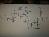
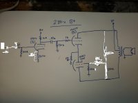
I have cobbled together and modified a few headphone amp designs that I found on the internet to utilize parts that I have on hand. I have built a working single-channel prototype and it seems to work well with an extreme amount of gain into my cheapo standard impedance headphones. I was hoping that someone a bit more well versed in tube amp theory could tell me if anything is inherently wrong here. My goal was to create a cheap but functional design. Total bill of materials not including an enclosure should be ~$100. B+ is 230vdc but I still get an acceptable amount of gain at 120v through a regular isolation transformer. I didn't change any component values for the lower voltage. I just changed power supplies. The output transformer is a Dukane line matching transformer. Primary~15k to an 8 ohm secondary. This isn't specifically what it is designed for but they cost $4 each and are rated to 4 watts. The sound isn't too shabby either. The design would use three 12at7 tubes. 12au7s also work, but have less gain. Still way more than necessary at the 230v B+ though. I haven't tried any other tubes in it. Power supply is just a typical transformer/ bridge rectifier/ pi filter setup.
Anyway, sorry for the crudity of my lovely artwork and I appreciate the help.
Anyway, sorry for the crudity of my lovely artwork and I appreciate the help.
Attachments
Last edited:
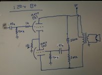
I'd decrease both of the 220k resistors to 100k (or even 50k), and increase the 270k to 330k.
Also add a 1M across the input RCA jack, and move the input 1k directly to the grid.
Second for removing the input bypass capacitor. Post some scope waveforms if you can.
Also add a 1M across the input RCA jack, and move the input 1k directly to the grid.
Second for removing the input bypass capacitor. Post some scope waveforms if you can.
Last edited:
What would happen if you made the 1st tube a "cathodyne" driver for the 2nd pair? Ala The Valve Wizard ? That would reduce the gain...
jjasniew,
A cathodyne grid has to be biased up to about 1/3 of B+.
A coupling cap from that grid has to charge/discharge, and that charge goes back to the input of the amp. It is going to apply 1/3 of B+ back to the tape head, every time the amp is turned on, and every time the amp is turned off. Bad!
Time to degauss the head again!
The cathodyne gain is slightly less than unity.
Now you have too little gain.
"Everything should be made as simple as possible, but no simpler" - Albert Einstein
Last edited:
It should be noted that the 220k resistors will have 0V signal to the grid of the one output tube when the plate voltage amplitudes are identical, but opposite in phase.
That resistive divider should be set to make up for the gain of the triodes in that circuit.
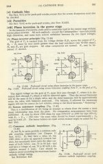
As it is now, what makes that circuit work is the cathodes that are connected to each other, and those common cathodes through 150 Ohms to ground. That is where the phase inversion takes place;
not the two 220k resistors.
If you doubt that, then disconnect both 220k resistors from the plates/transformer primaries, and connect those ends to ground.
It will work virtually the same (unless the number of turns from the center tap to one plate lead, do not equal the number of turns from the center tap to the other plate lead).
That resistive divider should be set to make up for the gain of the triodes in that circuit.
As it is now, what makes that circuit work is the cathodes that are connected to each other, and those common cathodes through 150 Ohms to ground. That is where the phase inversion takes place;
not the two 220k resistors.
If you doubt that, then disconnect both 220k resistors from the plates/transformer primaries, and connect those ends to ground.
It will work virtually the same (unless the number of turns from the center tap to one plate lead, do not equal the number of turns from the center tap to the other plate lead).
Last edited:
There's nothing inherently wrong with it. It will 'work'. Make sure that .22u cap is rated for more than twice the B+, and the 200k resistors will need to be at least 1W rated (because they need a high voltage rating, not because they will dissipate much power).
Ketje,
Aha!
1. Thanks for calculating the resistor values to split the voltage properly!
2. The way it was originally, the capacitor might as well have connected from the grid and 330k, to the OPT center tap. Would have saved a couple of resistors, but would also require a couple of back to back zener diodes from that grid to ground.
Just a silly way to illustrate how using a divider with identical resistances does not do anything, when it is dividing the push and pull signal voltages from a good OPT.
[Do not do # 2.]
Last edited:
Wow. Thank you for the responses. Too much gain wasn't necessarily a problem. Just thought it relevant to mention that it can seriously blow your hair back if that's your goal. Removing the 220u bypass cap does drop it a bit though. Removing the first stage altogether drops overall gain a bit too much though. I'm going to change up a bunch of stuff and I can get you some scope readings but it's going to be next weekend. I don't have time to work on it during the week. Just let me know what you would like to see. I don't know how I didn't notice the 0v on the signal divider either... The original schem called for a pot between two different resistor sizes. (balance pot?) I'm including the original schem for reference. I didn't have the correct pot so I just stuck a couple of resistors in there without considering their values. I'm good like that. :/ The film caps that I'm using are all rated to 630vDC at least. I went to mess with it a bit more last night and it started doing an oscillation/feedback overload/squeal sound whenever I hooked the .22 cap up to the 270k/grid junction. No doubt related to those two resistors, but I had run out of time to play with it. I really appreciate the replies, guys. I learn by doing so this is really great for me.
Attachments
It should be noted that the 220k resistors will have 0V signal to the grid of the one output tube when the plate voltage amplitudes are identical, but opposite in phase.
That resistive divider should be set to make up for the gain of the triodes in that circuit.
It will work anyway, as any floating paraphase does. The power section as depicted isn't anything else than a floating paraphase PI with the OT as plate loads.
Best regards!
Since I have not much to do, I change the feedback and the screen decoupling in your last posted schematic.😀The original schem called for a pot between two different resistor sizes. (balance pot?) I'm including the original schem for reference.
Why making live difficult ? In the schematic I posted earlyer the resistor values where allready change.I went to mess with it a bit more last night and it started doing an oscillation/feedback overload/squeal sound whenever I hooked the .22 cap up to the 270k/grid junction. No doubt related to those two resistors, but I had run out of time to play with it.
If you invert the values you get positive feedback, with the result you know by now 😱
Mona
Attachments
I was messing with it before I realised that I had replies. I'm going to try what you've suggested this weekend when I have more than a few minutes to devote to it. In the meantime I've been watching videos on theory from a dude named uncle Doug on YouTube. He explains it all in a way I can understand it. I'll post an update once I get the changes implemented. I really do appreciate the help.
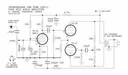
Anything inherently wrong with this design?
Depends on what you want to do with it. Aside from the use of a 6M11 the cct is not new & has been used since before WW2. At that time the advantage was a manufacturer could claim PP operation, an important marketing point. Refer to the cct on p585 of the Radiotron Designers HB.
Out of curiosity I bench tested several self inverting output stages a few years ago based on a pair of 6V6s. None of the ccts tried could deliver more than one-half what the same tubes were capable of when driven by an ordinary phase inverter. The cct must be run in Class A.
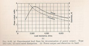
The PP triode sections of the 6M11 will need much higher load than 16K P-P, based on the published rp of 10K each. That forms a 20K generator driving just 16K, putting the triodes into a high distortion mode. The load impedance needs to be 30K minimum & better still at 40K. The attached curve shewing D% vs load impedance for a 2A3 is ubiquitous, the shape of the curve applies to any common triode. Only the scale factors change.
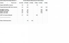
A summary of the tests is attached. I tried cathode tails of resistors, chokes & NFETs. Chokes gave the best results, but not as good a an ordinary phase inverter driven stage.
One cct of that era that did not cheat was based on a 6F6 accompanied by a low mu triode stuffed inside the same bottle. So a valid phase inversion was possible. That would be the 6AD7, now as expensive as UnObtanium.🙂
Depends on what you want to do with it. Aside from the use of a 6M11 the cct is not new & has been used since before WW2. At that time the advantage was a manufacturer could claim PP operation, an important marketing point. Refer to the cct on p585 of the Radiotron Designers HB.
Out of curiosity I bench tested several self inverting output stages a few years ago based on a pair of 6V6s. None of the ccts tried could deliver more than one-half what the same tubes were capable of when driven by an ordinary phase inverter. The cct must be run in Class A.
The PP triode sections of the 6M11 will need much higher load than 16K P-P, based on the published rp of 10K each. That forms a 20K generator driving just 16K, putting the triodes into a high distortion mode. The load impedance needs to be 30K minimum & better still at 40K. The attached curve shewing D% vs load impedance for a 2A3 is ubiquitous, the shape of the curve applies to any common triode. Only the scale factors change.
A summary of the tests is attached. I tried cathode tails of resistors, chokes & NFETs. Chokes gave the best results, but not as good a an ordinary phase inverter driven stage.
One cct of that era that did not cheat was based on a 6F6 accompanied by a low mu triode stuffed inside the same bottle. So a valid phase inversion was possible. That would be the 6AD7, now as expensive as UnObtanium.🙂
Attachments
My goal is to come up with a cheap tube headphone amp using readily available parts (preferably ones I have) that is powerful enough to make even the quietest tracks loud enough to be uncomfortable (just in case the power is ever needed). A reasonable amount of fidelity would also be preferred. That design was just simple and I adapted it to use 12at7's (albeit poorly) since I have 5 of them on hand. A true phase inverter is not out of the question. I have several more 12at7s and they're cheap anyway. I'd just have to account for the additional current requirements. I also have several other dual triodes in my collection. Several of them are in a tall bottle 9-pin noval config and I'm not sure why. Two 6cg7's for example among others. I'm not sure why they'd need to be bigger since they're just medium mu dual triodes.
The first design I tried used cheap and readily available rf triode/pentode 9-pin tubes as one-tube-per-channel amps in a typical triode/se pentode config. They worked and produced a stupid amount of gain but had very little bass as one might expect. Then I found the above design. I had never heard of a PP triode so I figured what the hey. So that's where I'm at. Im going to try everyone's suggestions and go from there. Hopefully learn a few things too since that's half the fun.
The first design I tried used cheap and readily available rf triode/pentode 9-pin tubes as one-tube-per-channel amps in a typical triode/se pentode config. They worked and produced a stupid amount of gain but had very little bass as one might expect. Then I found the above design. I had never heard of a PP triode so I figured what the hey. So that's where I'm at. Im going to try everyone's suggestions and go from there. Hopefully learn a few things too since that's half the fun.
Last edited:
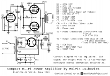
Another way to dump gain (and parts) is to go for something that looks more like "The Compact Amp".
That cct is essentially the one that gave the test results 'Popular Electronics 250R Tail'. I'll post some of the Scope & Spectrum shots later.🙂
My goal is to come up with a cheap tube headphone amp using readily available parts (preferably ones I have) that is powerful enough to make even the quietest tracks loud enough to be uncomfortable (just in case the power is ever needed). A reasonable amount of fidelity would also be preferred. That design was just simple and I adapted it to use 12at7's (albeit poorly) since I have 5 of them on hand. A true phase inverter is not out of the question. I have several more 12at7s and they're cheap anyway. I'd just have to account for the additional current requirements. I also have several other dual triodes in my collection. Several of them are in a tall bottle 9-pin noval config and I'm not sure why. Two 6cg7's for example among others. I'm not sure why they'd need to be bigger since they're just medium mu dual triodes.
The first design I tried used cheap and readily available rf triode/pentode 9-pin tubes as one-tube-per-channel amps in a typical triode/se pentode config. They worked and produced a stupid amount of gain but had very little bass as one might expect. Then I found the above design. I had never heard of a PP triode so I figured what the hey. So that's where I'm at. Im going to try everyone's suggestions and go from there. Hopefully learn a few things too since that's half the fun.
One 6CG7 in PP would be a very good choice. Could be driven by any number of different tubes. Your 16K P-P would be a good match.🙂
- Home
- Amplifiers
- Tubes / Valves
- Anything inherently wrong with this design?