Low or crackling sound in speakers

Good morning,

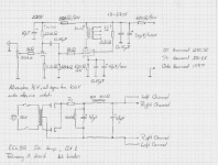
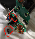
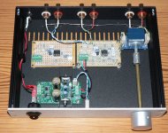
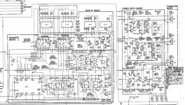
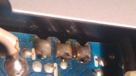
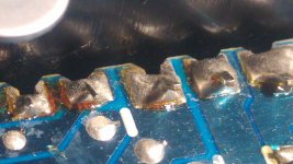
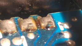
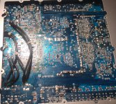
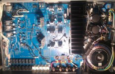
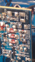
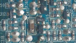
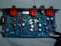
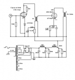
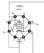
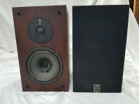
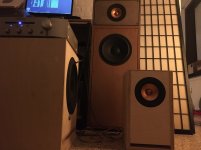
I've recently bought an Audio-Technica turntable (it should arrive next week) so I decided to retrieve my father's integrated amplifier. It's a Sony LBT-V701, about 20-25 years old, which apparently worked just fine the last time it was used. However, when I plug my smartphone or my Echo Dot into it, the sound that comes through the speakers is either low (when plugged into the CD inputs -there're no AUX input) or crackling (when plugged into the PHONO inputs). I'm using a 3.5 mini-jack and 2x RCA cable. I've tested it with two different pairs of speakers (both came with mini HiFi systems), that work perfectly well except with the amplifier.

I'm not precisely an expert in audio systems, just an amateur, so maybe I'm missing something here. Just to let you know: (1) the volume both in the phone and the amp was turned max; (2) the amp doesn't have a tape monitor switch.

Thank you in advance.

Alternatives to Dayton ND16-FA6

Hi all,

I am Interested in trying to add a tweeter to my JMLC 350Hz horn and make it semi coax.

Currently using a 1.5 inch exit JBL 2452SL (4 inch diaphragm compression driver)

The aim is to make it closer to CD.

Currently the pattern narrows in directivity as frequency increases considerably. I would like to hear what it sounds like with a wider top end.

Pattern narrows down to about 15 degrees at 10 khz (see chart in link below this paragraph)- however note my driver is 1.5 inch, and does not show the widening anomaly at high frequencies)

JMLC-350 – Horns by Auto-Tech

I can 3D print, so would make the necessery mount fit smoothly to the existing horn, perhaps in the middle of the throat, but not too far inside.

I'm sure someone has tried this before.

Is it a good idea?

Can small 5/8 or 3/4 Inch tweeters like the Dayton ND16-FA6 produce over 100db SPL if crossed over at 7 or 8 khz? High SPL is a reasonable priority as I love big classical dynamics!

Are there any better alternatives for a very small tweeter with high SPL and low distortion crossing at 7khz or so?

I would consider changing the horn for a CD one, but the only alternative spherical horn with a roundover on the mouth (needed for aesthetic reasons) is a tractrix. This is wider pattern, but not massively, so and they are not as good looking IMO anyway.

I would love a SEOS or OSWG, but they are not available in a spherical shape and 350hz pattern holding (as far as I know?)

The M2 horn is available, but is not free standing or aesthetically acceptable without mounting in a cabinet.

I propose placing the tweeter where the coin is in the image below, half way down the throat in a smooth 3D printed bullet enclosure.

Shared album - lance bartlett - Google Photos

Any suggestions/advice welcome!

Building an ECL82 Single Ended Amp ...

I've already asked some power supply specific question in another thread and received quite valuable information. Now I would like to share my ongoing building experience of my first tube amlifier.

Initially I wanted to build the EL34 amplifier but I quickly dropped it for a simpler and less expensive idea. With some assistance I picked the ECL82. Initially I thought I'd simply follow someone elses lead but then decided to study the ECL82 datasheet, read some schematics and articles and come up with my "own" design. As much as one could call it that, take the datasheet suggestion and make a few design choices.

I decided to operate the ECL82 with a B+ of 270V and a OT impedance of close to 8k. The equipment driving the amp will produce up to 2V rms at maximum volume, therefore I did not bypass the cathode resistor of the triode to reduce overall gain. The rectifier is a EZ81. Per datasheet the EZ80 should have worked but required higher PT secondary. PSUDII complained about exeeding the EZ80 maximum ratings. I wanted to play it safe and settled on the EZ81 instead.

I am not new to electronics. Learned the "Radio and Television Technician" trade in Germany after highschool. I worked in the electronic repair business for many years, first in Germany and later in Canada. Nearly a decade ago I switched careers and entered the IT field. Designing and building electronic circuits, be it analog, microcontroller or RF (amateur radio) has always been a passion. But until now I never got around to building with tubes. In my youth I restored a few tube radios (even repaired a few tube TVs) but otherwise only worked with solid state gear. Recent events in my life have brought back memories of the warm sound of tubes, the smell of heated dust and the glow of the tubes. So here I am building a tube amp.

The schematic of the first cut of the design is attached. I'd really appreciate some input as to what I've brewed here, good or bad.

Adi

Attachments

  • ecl82_se_cut_1_small.gif
    ecl82_se_cut_1_small.gif
    75.9 KB · Views: 3,842

6j1 tube preamp gain or buffer?

I recently bought this 6j1 tube preamp/headphone amp
Amazon.com: 12V DIY Preamplifier Kit 6J1 Preamp Tube Board Preamplifier 3.5MM Headphone Amplifier Replacement: Electronics

I like how it sounds through the headphones, and would like to use the preamp outputs to drive a class D power amp board.

Does anyone know how to find the gain at the preamp outputs? A buffer stage or does it actually amplify the signal? (I could not find any schematics online on this specific model)
Thank you

Crown k2 help

Hi,I need a bit of help with a crown k2 that I'm trying to repair.the problem is that the amp seems to be power cycling,when feeding a signal the signal lights will glow brighter as does the power light but then the audio cuts out and all lights dim as if the amp is going to sleep but then will kick in again randomly.

I put a link in to bypass the sleep circuit but the problem persists

I removed the input board and there is nothing obvious.

Any help is appreciated

TU-8340VK Noisy in Right Channel

Hi All,


I have been getting an increasingly bad noise in the right channel of my ELEKIT 8340 for a while now. Just intermittent to start, but now there all the time. I have checked all the usual starting points, so not valves or external stuff, speakers, leads etc. Sounds like maybe a bad resistor/component or solder joint.

I need to lift the hood and start looking inside for the issue. I am going to go over everything and re-flow solder and check for dry joints etc, but any useful hints or potential component issues anyone else has found previously would be appreciated.

This has been my main stereo amp for over 3 years now and with the transformer upgrade is a fantastic amp. Getting lots of extra use due to COVID isolation time, and I have the time to tinker and fix.


Any help greatly appreciated.


DjK

Looking for black pin/motorassembly for DATM53 Sony 2000ES/77ES/87ES/PCM2700/R7

I am looking for the black pin/leaver that transfers movement from the solenoid to the brake leavers or a complete motor assembly for the Sony DATM-53 drive, or a defect drive. Its used on all Sony 4 head DATs: 2000ES/77ES/87ES/PCM2700/R700.

Attachments

  • Screenshot 2020-07-02 at 21.15.06.png
    Screenshot 2020-07-02 at 21.15.06.png
    165.9 KB · Views: 61

Active pre amp DC offset increases with 2 modules used

I built a small active pre amp that uses 2 different modules sharing the same power supply.

Each module when tested gives a 0mV DC offset but when both are used together the DC offset rises to 30mV in the first stage and also some odd readings in the second stage.

First stage is basically a ESP P88 light with LM4562 with a gain of 2 using the front and back end of this pre amp design. It has 2 outputs in parallel with one as a pre out and the other feeds a sub output via mixing resistors and NE5534 with a gain of 3. These are powered by 7812/7912 regs from a 12VAC plug pack.

I also tried a NE5532 module with one half unused and wired as per TI implementation and has the same result.

The pic shows the layout but the sub module is not wired as at the moment is has dual pre outs.

I'm a bit puzzled with this result as I've looked at sub out schematics on some commercial amps but maybe I should feed both modules from the pot and not input the second sub module from the output of the first pre amp module.

Where have I gone wrong?

Attachments

  • RZ_pre4562_plus_sub.jpg
    RZ_pre4562_plus_sub.jpg
    264.4 KB · Views: 193

toroidal transformer hum

Hi, i built amplifier called av160 and its working, but there is one problem, humming toroidal tranfsormer 600w 2 x 40v secondary and primary 240v, tried to connect 0.1uF MKT X2 275AC rated capacitor on mains in parralel but that didnt worked, any suggestions how to eliminate humming, when amplifier is working and music not playing you can hear like from 2 meters that humming toroidal in silent room....😕

uni student looking for some advice

Hello! i'm an Electrical and Electronic Engineering student at Cardiff University, travel plans for this summer have been postponed for obvious reasons so i'm looking into some audio projects to occupy myself during the periods of inevitably rubbish weather here in south England/Wales.

I've done some reading of D. Self and B. Cordell's books, along with two years of uni work including analogue circuit design, control engineering, power systems and FPGA embedded design. I think it's time to actually build something that i'm interested in.

TLDR;

My aim is to 'design' and build a class A/B power amp, preamp with volume control, and maybe even an FPGA based DAC as i'm fairly familiar with Verilog already. So, as far as purchasing some gear;

Scope: Siglent SDS1202X-E, i've been offered 20% off a new unit.

DC bench power supply: Any cheap eBay linear supply? do I need to worry about output ripple too much? anything I should avoid?

Signal generation/measurement: this I am quite stuck on, I see people using soundcards like the "Behringer UMC 202HD" to make low distortion measurements, is it possible/advisable to use the same soundcard to generate and measure the same waveform?

FPGA dev board: anyone attempted something similar to this before?

I already have two multimetres/soldering iron/breadboards etc..

Any advice/insight/problems I will face would be greatly appreciated, i'm not trying to invent anything new here, just build upon my understanding, and who knows, maybe even power two bookshelf speakers with some half decent sound quality!

Thanks! 🙂

DC motor speed control

Good day all.
I need some advice plse. I have a motor that is mounted on a rotisserie, It works from 3Vdc ( 2x 1.5V batteries in series). I want to make an adjustable circuit between 3 to 5Vdc to drive the motor without having to worry about batteries.I have 12V 1.5A smps's that I want to use as they are small.
the resistance of the motor is 2.8R, meaning the current will be 1.071A at 3V and 1.78A at 5 volt. Watts drawn will be 3.21 and 8.9 watt respectively.
I have used a 11R 25 watt resistor as a voltage divider to test, The voltage is almost 3Vdc but the resister gets hot soon. What would be the easiest way to control the motor without having to use a bulky circuit, well I can all way's use a long connecting lead. This is what I have in mind, Would be using a mosfet work better ? Help appreciated🙂

Attachments

  • motor.jpg
    motor.jpg
    17.1 KB · Views: 267

Wifi Audio streaming device without internet

Hello guys

I apologize in advance If this topic doesn't come under the forum rules.

Im looking for a wifi audio streaming device which do not require internet access.

Requirements

Needs to stream locally stored audio from computer or smartphone hard disk via wifi.

Streamer should have a digital out to connect to a dac.

It should not require internet access but should be able to stream it via wifi router or mobile hotspot from devices connected to the same network.

It should not break the bank (approx cost 100 to 150 $)


If you guys know any device which fits the above criterias please share your information.

Thanks

Monitor audio ma4 series 1 crossover

I've recently picked up a very clean pair of these speakers and I'm liking them so far and was planning on recapping the crossovers but with a bit of digging online I found they used the same crossovers across a fair bit of their range.

The thing is tho they used the same crossovers for the b200 sp1039 which mine use and also the sp1014 which is a different driver in most ways but they must of thought it worked, well I've got a set of falcon acoustics 37k crossovers designed for the b200 sp1014 and t27 that look better than the ma crossovers, does anyone think it would be worth while giving them a try?

24 bit 96 k FLAC, what am I doing wrong?

When I play 24 bit 96 kHz FLAC files from my laptop, using Foobar2000, via USB, to my DAC (Pro-Ject Pre Box S2 Digital), the display on the DAC says 48 kHz. The Foobar application screen says 96 kHz. I suspect that somewhere along the line the 96 kHz is being down sampled to 48 k.

Do I need a special driver to support USB bit rates at 96k? Do I need ASIO drivers ?

16 x Satori WO24P-8 in wall subwoofer

Hi

For my new theater I am building an on wall baffle of sorts and I will build my own subs for it, since I can't really find a decent commerciel one. The subs will flank on wall speakers behind an acoustically transparent screen 15' wide. Limiting factor is depth. I have a lot of volume.

I have modelled many many many drivers but best compromise seems to be the Satori WO24P-8.

I have room for 32 of them, but I wanted to start with 2 x 8 in 2 arrays.

Questions:

* Optimal volume sealed pr. woofer?

(WINISD is fine, but practical experience?)

* How to best wire 8 pieces

(go for a 4 ohm load?)

Regards

Claus

Hi-End and Hi-Efficency loudspeakers (horn + onken)

Who produce these midrange ?
http://www.6moons.com/audioreviews/duomega/upgrade.html

----

I am starting a project using the Beyma CP380M compression driver with this horn:
http://www.stereo-lab.de/tractrix.html
cf600 1" model

As woofer probably I will use this 15" in onken box
IMG StageLine SP-15A/402PA

http://www.monacor.de/typo3/index.php?id=58&L=2&act=8&act_sub=24&artid=6071&spr=IT&typ=u

crossover 800Hz - 12 or 18db/oct

Attachments

  • strip7.jpg
    strip7.jpg
    48.4 KB · Views: 6,316

Fiberglass filled "reflex" boxes -driver pick ? (VMPS style)

The late Brian Cheney, at least with his early VMPS offerings, typically put two polycone woofers of dissimilar T-S, driver diameter, in a tall tower, pretty much filled the cabinet with fiberglass. There was a floor facing Morite weighted passive radiator at the bottom of the tower and that PR fired out a slot whose area, which IIRC, was smaller than the PR's Sd. There was no filter on the paralleled woofers (could have used one with the Super Tower 2).

This didn't seem to be such a bad way to approach some loudspeakers - other than eventual PR sag.

Are there good fudges for 2 dissimilar woofers and a slot loaded passive radiator in hornresp?

Anode coupled circlotron with transformer

Hello everyone, silly questions are coming for some

I have found many information about circlotronic circuits, all cathode coupled. Some with transformer and a lot more transformerless.

I was wondering, how can i reduce the output impedance of an OPT without the need of huge driving voltage swing? Why not an anode coupled circlotron?

I can see the need of several separated PSUs. What other drawbacks are there? There must be a reason i can't find such an approach, not even in a test bed as failure

Below you can see what i mean
1.jpg

SMPS - switching frequency, ripple, leakage tradeoffs for class-D?

I recently finished the tpa3255 reference design here

Are there any good reads on what to prioritize when looking at SMPS?

Can it be drilled down in to comparing a few stats? Or is it harder to quantify than that?

Or is it mostly down to the design of an amp being more or less sensitive to power quality?


If you look at a big name manufacturer like Benchmark they seem to favor higher switching frequencies and thus smaller transformers here

I'd like to go with a smaller, higher frequency smps (I don't care too much about wattage) like this: CFM150S480-B

It's only 4 inches x 2 inches and has a switching frequency of 115khz and very low idle power draw, but it has a ripple of 1%.

TL084 to???

Hi All,

I have an electronic xo and servo circuit board that was built around the TL084 opamps that is very noisy. Using the high pass section in the unit to the HF amp and not using the HF section in the unit is night and day different however I would like to high pass my speakers as intended by the unit.

My concern is the actual circuit and layout is the cause of the noise and not the TL084. However it is easier to try a different opamp first before I go down the path of redesigning the whole circuit and PCB.

Is there a pin compatible opamp for the TL084? The TI website says a replacement is the TLE2074 however it is a different package.
Anyone know of an adapter to an 8 pin dip?

16ohm Midwoofer in a 3way design

Hi everyone!

I am planning of building a 3way design with a Focal tweeter, PHL Midwoofer and 2 Peerless woofers I have at home.

Focal is 6ohms
PHL 16ohms
Peerless 8ohms (each) - 4 ohms in paralell

It will probably be a bi-amp system. Separate Mid/High and Lows.

My question is;
- How unfriendly actually is a 16ohm midwoofer for crossover design and amplifier matching.

Should I choose a more suitable mid for this system? Should I get a different midrange? 8ohms?

Thank you all : )

Sony ST-A7B frequency display

A friend got this Sony tuner and brought it to me to repair the “frozen” frequency display, which is a known problem and fairly easy to solve.

After the repair, the tuner was working the whole evening until a brief power grid blink, for a couple of seconds, so when the power was restored the tuner remained silent. A 15,3V circuit breaker went off and a transistor Q805 on counter PCB had to be replaced. But now the frequency display behaves weirdly: between 90 and 104 MHz it shows the correct number. However, under 90MHz it will display almot double the frequency (not exact multiplication), whereas above 104MHz it will restart counting from 88.4MHz. Otherwise, the tuner operates just fine.

I have narrowed down the problem to the counter PCB. Further details:
- transistors Q801-Q804 test OK
- Q801, Q802 and Q805 show correct collector voltages as indicated in the schematic, however only in the 90-104MHz range, otherwise they show the opposite values
- IC801, IC802 get considerably warmer than other chips on the board, but this may just be normal
- I did not check all voltages on IC pins as referenced on the schematic because the manual does not indicate the measurement condition (i.e. the tuning frequency) and so they are sometimes there and sometimes not, depending on the tuning frequency

I am kindly asking for help to identify the IC on this board which is responsible for erroneous frequency reading in some ranges. Thanks in advance.

Attachments

  • Screenshot 2020-07-01 at 23.20.42.png
    Screenshot 2020-07-01 at 23.20.42.png
    650.1 KB · Views: 118

May be a long shot identifying a speaker

Hello all,

I have been looking for a pair of speakers I saw at a friend of a friends apartment back in the early 80's. I don't recall the brand, but they were high end and the owner was a Marine stationed at an embassy somewhere in Japan? and purchased them at the PX or a local business.

They where about 4.5 or 5 feet tall pyramid shape dark wood or plastic cabinets topped with a plasma tweeter in a clear plastic or Plexiglas enclosure that was shaped to complete the pyramid.

My memory may be a bit off but the uniqueness in shape and design is hard not to remember. Surely someone in this group may recall something similar to my description. If this sounds even slightly familiar I would be grateful for a brand name and or model, pictures or whatever you may recall.

Thanks,
Bill

Little help with VU meters.

Hi, I was preparing to make this VU meter driver A simple passive logarithmic VU-meter on breadboard when I saw topic on this forum about this board:
s-l1600.jpg

s-l1600.jpg

This is schematic I planned to use for breadboard project:
vu-meter-circuit.gif


By parts they seem pretty close, could I somehow omit opamp and power stage from this board and use it like VU driver from schematic? 😀

Will post sch from ebay board if I manage to find it, thanks.

I think IC is lm358n
HTB1AvI4RFXXXXauapXXq6xXFXXXv.jpg


This board could help, they are pretty similar:
TekRam-TA7318P.jpg

2783875400_1462173712.jpg

BLH/TL Build for Dayton RS100-4

Hello all!
I haven't been around in a while but the speaker building and design bug is always there. Anyone interested in a public build, open source small BLH/TL for the Dayton RS100-4? I just purchased a pair and spent some time working within a few parameters that I have decided I need in a small driver point source build. The build must meet the following:
1. Easy to build (less than 20 pieces and no complex angles).
2. Cheap to build if desired by the average builder.
3. I am not trying to cover so much of the spectrum as many (including myself in the past) have. I don't really want the unit to go below 55-60 Hz as I want to be able to play fairly complex music and might even high pass the speaker so as to allow for higher volume with lower distortion or more complexity with lower distortion.
4. I want it to be compact.
5. Above all sound quality will be king. I don't want to use too many "room tricks" to gain what I have set out to build. I want the mouth fairly close to the driver so they merge more effectively.
6. Will use an independently powered sub of some sort for the real low material so keeping the horn and TL working within the limits of the driver are a reality.

I attached a Sketchup rendering of what I have so far and would absolutely love if others wanted to build with me so we can all work on whats right, wrong and could be better. Leave a message in this thread if you want to take a shot at it. I'll draw up the full plans and post them here for all to use. Any input from Martin, Dave, Scott, GM, Chris or anyone else with advanced knowledge of what I am working with is always welcome! Now for a couple of specs on the enclosure I have drawn up so far.

-760 Hz mouth
-50 Hz flare
-55Hz TL length
-F3 of 55 Hz or so

Martin, I will be over on your page within a week or so to pay for firing up the worksheets again.

11329801614_ec540e5d7d_o.jpg
11329758716_9e3ec9ca30_o.jpg
11353368636_9cdb3a30a2_o.jpg

Total noob - want to build (assemble) 6-channel amp

I was convinced in another thread to go the route of building my own class D amp. It was this link that really convinced me:

Six channel DIY Anaview AMS0100 amplifier

So, I've recently just gone down the path of active XO, and this would be part of that build. I would like some help figuring out what I need to replicate the amp in the link above, but with some modifications.

1) I am not sure what's going on with the company whose parts are used in that amp. There seems to be a question about whether they still sell small quantities to consumers. I've contacted them, will wait for reply. In the meantime, an alternative source would be great.

2) I would like to know how easy/possible it would be to include any DSP in a build like this, so that I could have the XO function contained here, as well.

3) It would appreciate advice/help (not actually hands-on help) from anyone who loves hobby building. I'm not an electronics guy. But I am building this with my son, who is interested in pursuing an EE degree. It's a father/son project. I don't mind just piecing together components.

4) We love a great cost to value ratio. I don't think we need to break the bank to get something that sounds great. (I'm half deaf, anyway)

That being said, I have a set of speakers with no XO's at one end, and a receiver and pre-amp at the other. It would be my preference to build a 6 channel, so that I can do a 4-way build in the future. (with subs on a separate amp) I'm open to any and all recommendations.

I come armed with basic soldering skills, and the ability to ask questions. 🙂

embedding a DMM into a bench-top instrument panel

Hello all,
I'm the owner of 4 DMM, all middle range models, eg UNI-T UT61E, Voltcraft VC 850, etc. I'm redesigning my workspace with a new bench. It will have a vertical stack of 2, maybe 3 surfaces to hold the scope, signal generator, PSU, etc. I sort of do not like handheld DMMs, they take a lot of valuable benchtop space and cabling is messy, always need to be re-organized, etc. Obviously, benchtop DMM would be a solution but their prices (new modern devices, or older good brands like Fluke or HP) are somewhat high for my usage... and I already have 4 handheld devices... so I came to the idea of vertically embedding them into a panel. I do have the tools for some woodworking, but it's not that easy, as they often have no screw taps behind, have cumbersome formats, and the back-panel need to be accessed to replace their batteries.

Anyone has done something like this and can recommend a sane approach ?
Thanks, Charles

A little TV Troubleshooting help on an Audio Forum?

Hoping this allowed. If not, Mods please do what you have to!

LG 32lc7dc Power off red led.

Power on: 18 Green blinks, then nothing but vertical lines (se below) and after a short while turns off.

Replaced the PS board and T-Con board. Could this be a Main board problem or the connections to the top/sides of the picture panel?

Thanks for any ideas!

Attachments

  • Resized_20200627_195557.jpg
    Resized_20200627_195557.jpg
    331.6 KB · Views: 121

How to connect 4 speakers (FL SL FR SR) to a 5.1 amp

Hello,
I have a set up of 4 full range speakers, FL SL FR and SR.
In the past they were connected to a stereo amp in parallel ( 2xLeft + 2xRight). This very amp just died so I want to improve the system and add a dimension to it.
Considering the amplification, I only know 5.1 as a configuration that support more channels than stereo. However I only have 4 speakers and I wonder if it is possible to connect these ones in such a way that we would be able to hear all channels (FL SL FR and SR).
My problem is that if I connect each channel to the proper speaker, I wont be able to hear the center channel and the sub since I don't have speakers for these.
Is there a way to connect the sub channel and the center channel to all the others speakers so I can hear all the signal but with a bit of spacialisation ?

Thanks a lot for considering this thread !

PS : Pardon my english if it is bad, I'm not native.

Audio Path Capacitors From Nichicon

I read that people use low leakage capacitors for audio path.
For example Nichicon UKL.

What about all audio capacitors from Nichicon?
They are not really low leakage capacitors.
Can/should they be used in audio path?

Nichicon is not offering much use examples info about their capacitors families. For example "Selected materials to create superior acoustic sound" of UKA series is not telling much to me (same as to anyone of you guys, right?)

By the way, anyone heard of UKA? Are they same good as FG or other audio capacitors from Nichicon?

Thanks

PS
interesting video here:
YouTube

FS:Dave Slagle filament modules and Coleman regs

Up for your consideration is a pr of Dave Slagle filament boards and a pr of Coleman regs. Everything is assembled and adjusted by Dave. The filament regs are the 1 amp version, and Dave had adjusted them to use on the type 26 triode. They of course can be adjusted to any other tube within the 1 amp rating. Everything is included except the appropriate heatsink, which of course is dependent on your application. please see Dave'a application notes on his website.

Price is $ 250.00 (the original cost of the filament boards ), and I'll throw in the assembled Coleman regs at that price. Shipping is $ 10.00 ( insured priority mail ) in the US only.

International buyers please note. Shipping and insurance costs are on you and will be quoted depending upon destination.

Haven't a clue how to post pics on this website. Send a request to my e-mail

wrm0325@comcast.net

and I'll send them to you directly.
thanks for looking.

Cheers, Crazy Bill

BTW, both items new and unused.

Small power supply for line level device

Just need a quick double-check on this;

I'm planning on using a Hammond 187C12 as a small transformer for a line level device power supply - freeDSP Aurora to be specific. Since this is center-tapped, I am going to put 1 diode on each windings (as opposed to the 4 for bridge rectification) for full-wave rectification where the center tap is the common (0 VDC). Maybe a two-diode device like this.

The transformer has (12.6 / 2) = 6.3 VAC RMS on each winding, so my rectified and smoothed output voltage (assuming high enough capacitance) should be (6.3 * 1.414 - 0.4) = 8.5 VDC.

Does that make sense? Did I make a mistake somewhere? Should I use bridge rectification anyway (will there be less power loss overall)? Also, what's the maximum C I should limit myself to, for this transformer?

Diagnose of my AMP, please

Guys, hello.
I just bought some second hand NAD C326BEE amp.
Seller stated that he was only owner of this amp and had never take it to extreme or had any issues with it. So, it was a lie 🙂
As I understand this amp had bad times, but looks like got fixed.

It seems to be working fine, but my "fine" is not very reliable, as I am new to whole WIFI field 🙂

So, I will be glad to know if I spent my money for nothing (~250GBP).
Please look at the pictures and tell me what you can say about condition of this amp, what possibly happen to it in the past (some soldering work, overheating, water damage, other).

I think of doing some repairing work future (recapping, replacing some other elements).

Thanks a lot.

Attachments

  • 20200219_212842.jpg
    20200219_212842.jpg
    361.1 KB · Views: 376
  • 20200219_213228.jpg
    20200219_213228.jpg
    397.9 KB · Views: 367
  • 20200219_213243.jpg
    20200219_213243.jpg
    263.7 KB · Views: 356
  • 20200219_213323.jpg
    20200219_213323.jpg
    316.8 KB · Views: 350
  • 20200219_213338.jpg
    20200219_213338.jpg
    229.3 KB · Views: 360
  • 20200219_214734.jpg
    20200219_214734.jpg
    808.9 KB · Views: 231
  • 20200219_215110.jpg
    20200219_215110.jpg
    727.7 KB · Views: 212
  • 20200219_215407.jpg
    20200219_215407.jpg
    329.5 KB · Views: 204
  • 20200219_215419.jpg
    20200219_215419.jpg
    370.5 KB · Views: 182
  • 20200221_105525.jpg
    20200221_105525.jpg
    322.8 KB · Views: 168

NAD PP2 Phono Preamp Upgrade

I just bought for a song an almost brand new NAD PP-2 Phono Preamp. I bought it to use before I finish my Ono preamp.
I can also compare the sound and see if my Ono is as good as the review are saying it is 😀

This is the inside. Pretty neat for such an inexpensive preamp. Already, for the price, it seems to be a bargain.😎

Very well built, metal film resistors, low noise transistors. Good quality, gold plated connectors, good, small casing. MM and MC separate inputs. Good specs. Difficult to beat even by diy.

If it is worth it, I plan to replace the cheap electrolytic caps inside with some Panasonic FC that I have in stock, can't hurt I guest.:angel:

Attachments

  • inside_small.jpg
    inside_small.jpg
    70.4 KB · Views: 4,887

Help please: Bias and hum

The C3g-45B monoblock is up and running. We have music played thru a speaker. But, a couple of items need help. Let's start with just the BIAS question.


BIAS on C3g driver tube

A 2.2V LED is used to bias the C3g. LED is connected from pin 7 to ground. LED lights up properly, but the measured voltage is + (positive), not the desired - (negative). The measurement is taken from the LED + to ground.

Here are some other measurements that may or not be useful:

C3g Anode to ground is -2.2Vdc without any B+ and with filament voltage only

C3g Anode to ground is +2.3Vdc with B+ and filament voltage

LED positive (+) leg to ground is +0.5Vdc without any B+ and with filament voltage only.

LED positive (+) leg to ground is +2.157Vdc with B+ and filament voltages on.

So, I am confused as to whether or not the + (positive) voltage measured on the LED is appropriate? I thought it should be negative.


We will tackle the 0.35V 60hz hum issue after we address the LED bias concern.

Thoughts?

Thanks

Attachments

  • C3g-45B v9.0.png
    C3g-45B v9.0.png
    48.3 KB · Views: 346
  • Screen Shot 2020-06-21 at 11.07.10 AM.png
    Screen Shot 2020-06-21 at 11.07.10 AM.png
    22.9 KB · Views: 340

CNC waveguide baffle 2-way

Greetings all - been a reader for a long time trying to learn enough to start engaging. I've got DIY aspirations, but recognize I need to learn a lot before I start learning a lot by doing.

As I've read more and learned about what ends up making great conventional speakers great, even and controlled (maybe wide) dispersion and flat on-axis are the keys. I've been frustrated with the waveguide tweeter options, but was excited to see a recent video from Joseph Crowe Audio about a 2-way design for DIY:
YouTube

This looks like a great design to sculpt the waveguide into the baffle that permits using a great-performing, reasonable cost dome tweeter from SB acoustics. I really like that the waveguide is integral to the baffle - it has a much more polished look, and it really seems to integrate the two drivers really well. In the video, he steps through how the handoff works particularly well with the horn-loaded tweeter's natural performance and his proposed first-over crossover design, and then goes into measured distortion to show that it's not a sacrifice.

Although this is a more complex speaker philosophy than I'd ordinarily take on for a first project, this actually looks like the baffle design does hard enough work that it actually *simplifies* the rest. This has jumped into my short-list of projects to cut my teeth on.. I'm just worried that I might not need to build again after it 😛

In the video, he says he'll be selling the baffle and the cabinet as a flatpack, but I think he sometimes sells 3D geometry for folks who have access to 3D printing (or maybe CNC?). Now to go read up on veneering cabinets some more...

DIY 2 way Floorstanding Speaker-Accuton Drivers

Here is a high grade floor standing speaker designed by Tony Gee of Humble Homemade HiFi. It’s based on Accuton C30-6-358 cell tweeter, 173-6-191E woofer, and 2 P173 passive radiators.
My cabinet differs slightly but the internal volume etc. is to original specifications. It is a translaminated construction of baltic birch plywood. I had the pieces cut with a CNC machine. The front baffle is 1” baltic birch epoxy laminated with a .25” sheet of aluminum. There is extensive interior cabinet bracing with a separate sealed compartment at the base for the crossover.

The cabinet is lined with .5” of felt and sheep wool stuffing.

The crossover was designed and modified after listening sessions over a year. I purchased the designed and assembled crossover from Humble Homemade HiFi.

Dimensions: 45"h x 10"w x 12"d

$1850.00 plus shipping. The speakers are located in Phoenix, Az

Attachments

  • IMG_6149.jpg
    IMG_6149.jpg
    768.6 KB · Views: 503
  • IMG_6151.jpg
    IMG_6151.jpg
    555.9 KB · Views: 497
  • IMG_6152.jpg
    IMG_6152.jpg
    655.5 KB · Views: 490
  • IMG_6153.jpg
    IMG_6153.jpg
    510.6 KB · Views: 449

NAD C 326BBE

I just aquired a new for me (circa 2007 based on a component date code) NAD c 326BBE amp. Havent even turned it on eyt, but decided to take a look inside first.

I was a bit surprised to see it populated with King-Sun (KSC) Aluminum Electrolytic Capacitors (China).

I looked at some old discriptions of NAD amps and seems they used hire quality compnents like ELNA caps but it was only a single exmaple.

For the switch pwoer supply, i dont think i much care as long as thay are doing what they need to do.

In the audio path though i am considering replacing the electrolytics with Panasonic FC caps and any electrolytics not in the audio path with some high-quality caps as appropriate.

i'm looking for some feedback on this from others, would you change them or leave them.

would you use different caps then i am considering in the audio path?

I'm also kinda curious of the venerable 3020 had noname caps in it as well?

New bookshelfs for Mark Audio Alpair 10M

I've moved houses and needed new bookshelfs for my office. I started it as Covid-19 project but got stuck on the lack of wood (also at my suppliers), but finally they are finished... I used Mark Audio Alpair 10M drivers out of an older project that i disregarded (my first build with Mark Audio) as i never listened to them anymore and putted them in a 17.9L ported box tuned to 45Hz and added a little LCR notch filter to flatten the sound in the treble.

I'm very happy with the build that happened this weekend with the help of a friend known here as humbledeer. We did also build a subwoofer at the same time for her setup. She is working on the final cad files of my builds, wich i will publish freely here with all the details. But here is the first picture of my build, still in a raw testing state. Sanding and finishing will happen later after i installed myself fully in this new house because it's still a mess of cardboard boxes...

Attachments

  • IMG_2108.jpg
    IMG_2108.jpg
    511.6 KB · Views: 298
  • IMG_2112.jpg
    IMG_2112.jpg
    466 KB · Views: 291
  • IMG_2117.JPG
    IMG_2117.JPG
    864.3 KB · Views: 303
  • IMG_2131.JPG
    IMG_2131.JPG
    812.2 KB · Views: 281

Do Old, Unused Computer Grade Electrolytics Age?

I suspect the answer is yes but that is just my guess.


I have a collection of unused, old (up to 50 years old) computer grade electrolytics. They are primarily Mallory, Sangamo and Sprague that I had bought surplus, but never used all of them. They appear to be completely intact.


I suspect that I shouldn't start a new project with them (if nothing else they are generally bigger than today's caps) but I was wondering if they age when they are unused.


I can't really measure them too well, since my LCR meter( a DER EE DE-5000) can't measure caps having capacitance of 10,000 to 15,000 uF.


Thanks.

50W + 50W TDA7492 CSR8635 Pre Amp ---- No Audio

Hi there,

I have recently bought this board off of Banggood to use learn about the CSR8635 bluetooth module mostly.

I attacked a 9V power Supply along with two 4 Ohm speakers and it worked perfectly. i then paused it and walked away to work on another project.

When i came back to it about half an hour later, the board was still connected however i was not able to get it to play music again.

I turned it on and off again, and even then there were no enabling sounds from the bluetooth coming out of the speakers.

I increased the power supply to 12V.

I shorted pin 10 and pin 8 as i found in a previous thread to constantly enable the boards pre amp and that didnt work.

I then pulled the RST pin of the CSR8635 to GND to force a reset of the board to see if there was another enabling problem but still to no avail.

The buttons on the board that control volume previous and next songs and pause still triggered on the phone i was using just no audio being outputted anymore.

Has anyone had a similar problem? if so is there a fix?

Any help is greatly appreciated.

Thanks,

Joe.

Power supply transformer for pre-amp

Could somebody recommend a transformer for a valve pre-amp with a 12ax7 and a 12at7 the first valve may need DC heater as I need some gain. So I need heater + HT with HT about 170-200V maybe about 3W HT. Problem is I need something off 230V UK mains. Hammond only do 115V mains.

20200619_180409.jpg


As I have just made this schoolboy error.


Something new I can order.


Cheers.

Find repair parts for Bose Amplifiers

On a "Bose L1 Compact Power Stand" (that looks like a little wood burner stove with a pipe sticking up) the volume control pots are very scratchy. They are small circuit board mount, dual pots (6 pin), they measure ~3/8" x 3/8" x 1" tall (including the shaft) the markings on the pots are " 10C 10K 9D4 ". Bose does not sell repair components to individuals. I have not been able to find the parts on Google. I can do the repair (50 yrs experience) if I can get the parts. Any suggestions or sources you have would be appreciated. Thanks, Rick

6db loss in compressor

Hello group,


I am having 6dB loss on my tube VM Compressor (stereo) even with bypass engaged. Tested as well with a sine at 1kHz. When Bypass is NOT engaged, that is to say, the compressor is engaged and with treshold at 0, the signal have 6dB loss as well and a roll off at low frecuencies, like a HPF at 40Hz.


For the 6dB loss, thinking that maybe I have one legged connection, due the loss is present with bypass engaged, I checked all D-Sub 25 pinouts from Soundcard Output to Patchbay, and DB-Sub 25 pinouts from Patchbay to Soundcard Inputs, and all polarities are correctly wired.


Checked the Compressor wiring from XLR in and out to input and outputs transforners and all looks correct.


One thing with this compressor is that one channel have to be wired inverse at the output otherwise there is a phase cancellation, which I do not understand too because L and R have not the same signal. This make me think that must be a mistake with the sidechain feed ?


Any help or hint is appreciated. Thanks in advance.

Ortho Acoustic WAW

This is a bit premature because I am not fully done with this build yet (still waiting for amp cards from China and I still got a filter to finish). But I got pretty exited when I finally manged to make a WAW that actually worked (you can read about it in this thread). But why stop there? I got a bit restless and wanted to build something new. It was the start of another W5-2143 based build, the Ortho Acoustic WAW 🙂

You can follow the build if you are interested on my blog: EmuMannen

The speakers are finished but I am still in the process of building a purpose built filter and replace the plate amps with something else (initially Tripath for the FR and TPA3251 for LF, to be replaced with TPA3251 for the FR and TPA3255 for LF as soon as I can get hold of a TPA3255 card).

  • Locked
Linux operating system -suitable for test and measurement software ?

I am from the Analog era of test and measurement equiptment , though I do have two digital multimeters.
I am intending to buy a computer , and want an operating system which will accept software for audio test and measurement.
I realise many audio engineers use Apple/Mac systems , though I prefer not to unless there is no other comprehensive option.
I don’t much like Windows either , thus I ask here ,
does the Linux operating system accept software packages for audio test and measurement ?
or are the useful audio test and measurement software all designed and manufactured only for Windows and Apple/Mac systems ?

Any information will be appreciated , or any reference to Threads in this Forum or elsewhere where the above is comprehensively covered.

Yes , you are correct , I really am not knowledgeable about computer systems.

Help wanted to setup PSU rails in JLH Mosfet amp!!

OK...I've been attempting to resurrect a couple of JLH 80W monoblocks!
I've got to the part where I'm setting up the rails of the PSU.
The construction manual states that:
" Occasionally the heavy current 55V supply rails, particularly the +ve one, will not setup without a load. If this happens, use two 1K5 1W resistors supplied in series across the line to earth rail to load it with a few milliamps"
Really need 'baby steps' here!!!

  • It's the -55v rail that is misbehaving for me.
  • I've got 3 x 1k(3W) resistors which i can connect in series...got that bit!
  • Then...connect the 55v output to ground (case) via the resistor chain???
  • Next step struggling....do I adjust rail 'under this load'....or remove load and go back to setting up rails as before???


The 'other' monoblock setup fine....both 50v and 55v rails... without this step BTW!!

Please advise...and thanks!! 🙂

2 Way 2 Pole Non-Switching CFA

attachment.php


This is the result of the circuits assambled , described in Non-switching complimentary output stage
https://www.diyaudio.com/forums/sol...com/forums/solid-state/356531-2-feedback.html
As one can see , the two way allows the use of sophisticated output stage , without stability problem as above 1Mhz is is shunted.
As it is stable I gave further local feedback to bring the open loop OS distortion down to 0.0015%.
For now, I have a problem with slew rate . It needs a buffer for the HF feedback feeding C7.

Attachments

  • 2POLE 2WAY CFA.JPG
    2POLE 2WAY CFA.JPG
    123.7 KB · Views: 280

Need help with car amp ppi900.4

Hi everyone I am trying to troubleshoot a ppi900.4 that has very low volume on the rear output sections. The gain is all the way up and the speakers are very quiet. The front section of the amp is good no problems there.

I opened the amp and checked with an oscilloscope every transistor and there are 6 T460 I imagine this is the output section. They all had the same square wave.

What should you look for if all the transistors that have to do with the output section are working at the same voltage ???

thank you !!

Pioneer six 737 refurb questions

Hi everyone

I have a pioneer sx 737 receiver amp which apart from a slightly crackly volume knob (which I am sure a squirt of deoxit it would fix) works fine and appears to be in good condition.
Having said all that, I know this amp has never been serviced or restored and have been thinking that a basic recap is well deserved and overdue.
I have never done this before and am no electronics expert, but I have built speaker x-overs and can read basic schematics and use a soldering iron.
My questions are as follows:
Am I mad to consider doing this myself?
if you were me and slightly daunted by doing everything, which basics would you tackle to get the best results for the smallest work to gain confidence and hopefully improved sound (power supply boards only)?
I am slightly nervous about investing a fortune into something that may not go according to plan!

Thanks for your time

Paul

Hafler DH110 schematics

I am currently refurbishing a Hafler DH110 preamp. Recap, change P.S. using Belleson regulators, motorized volumen ALPS pot for remote control, contacts cleaning (the wake point of this preamp),....


I wold like to have a copy of the schematics. I know that the owners manual can be downloaded from hafler.com, but it is a multiscanned copy with very bad quality. And I don´t want to spend 20+30$ for a copy of the owners manual on ebay.


I´ve been looking around in the web but I didn´t find it, just the same poor quality copy of hafler.com.


Should someone have a proper copy off thoose schematics and be so kind to send it to me?. Or a link of course.


Thanks in advance.

Throat in Radian 950 - is this right ?

I have had a pair of Radian 950PB (AL diaphragm) for about a year now and have been using them on a pair of Azura 340 horns. I liked what I was hearing and so I decided to upgrade to the Be version. The new drivers arrived today and the throats have a big step in them which is not present in my older 950's.
I have a bunch of compression drivers and I have never seen a big step like this in a throat.
All the other drivers I have are smoothly tapered and I always thought discontinuities in the throat/high pressure region of horns was something to be avoided.

Radian customer service says they have not changed the throat designs but the two examples I have are clearly and significantly different.

Is a step like this normal ?

Attachments

  • 20200702_191048.jpg
    20200702_191048.jpg
    966 KB · Views: 224
  • 20200702_191038.jpg
    20200702_191038.jpg
    1,000.2 KB · Views: 260
  • 20200702_191030.jpg
    20200702_191030.jpg
    771.4 KB · Views: 224
  • 20200702_191018.jpg
    20200702_191018.jpg
    569.6 KB · Views: 229

Burson Audio V5i Hybrid Opamp

Looking for a simple and good circuit design for an opamp preamp to go with my ACA that uses the dual "Burson Audio V5i Hybrid Opamp" that just became available on the site. It will need to use the same 24V single rail power supply as the ACA. Volume control not needed as I have that already with my source. Any suggestions? A project with available bare boards would be ideal, but not required. Thanks!
And... a simple and good design for a preamp using the same opamp with a differential input and the usual V+/V- supply. Thanks x2!
I've ordered the opamps already, cause, why not, and also got a number of ne5532's from digikey as guinea pigs.
Projects by fanatics, for fanatics
Get answers and advice for everyone wanting to learn the art of audio.
Join the Community
507,765
Members
7,887,509
Messages

Filter

Forum Statistics

Threads
406,182
Messages
7,887,509
Members
507,765
Latest member
Coreque