The C3g-45B monoblock is up and running. We have music played thru a speaker. But, a couple of items need help. Let's start with just the BIAS question.
BIAS on C3g driver tube
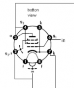
A 2.2V LED is used to bias the C3g. LED is connected from pin 7 to ground. LED lights up properly, but the measured voltage is + (positive), not the desired - (negative). The measurement is taken from the LED + to ground.
Here are some other measurements that may or not be useful:
C3g Anode to ground is -2.2Vdc without any B+ and with filament voltage only
C3g Anode to ground is +2.3Vdc with B+ and filament voltage
LED positive (+) leg to ground is +0.5Vdc without any B+ and with filament voltage only.
LED positive (+) leg to ground is +2.157Vdc with B+ and filament voltages on.
So, I am confused as to whether or not the + (positive) voltage measured on the LED is appropriate? I thought it should be negative.
We will tackle the 0.35V 60hz hum issue after we address the LED bias concern.
Thoughts?
Thanks
BIAS on C3g driver tube
A 2.2V LED is used to bias the C3g. LED is connected from pin 7 to ground. LED lights up properly, but the measured voltage is + (positive), not the desired - (negative). The measurement is taken from the LED + to ground.
Here are some other measurements that may or not be useful:
C3g Anode to ground is -2.2Vdc without any B+ and with filament voltage only
C3g Anode to ground is +2.3Vdc with B+ and filament voltage
LED positive (+) leg to ground is +0.5Vdc without any B+ and with filament voltage only.
LED positive (+) leg to ground is +2.157Vdc with B+ and filament voltages on.
So, I am confused as to whether or not the + (positive) voltage measured on the LED is appropriate? I thought it should be negative.
We will tackle the 0.35V 60hz hum issue after we address the LED bias concern.
Thoughts?
Thanks
Attachments

You want the cathode of the tube (and the anode of the LED) to be positive with respect to ground.
This makes the grid of the tube negative with respect to the cathode, which is correct.
To confirm this, with the B+ on, connect your voltmeter red positive lead to the grid,
and the black negative lead to the cathode, and you will get the correct Vgk bias value of -2.2VDC.
This makes the grid of the tube negative with respect to the cathode, which is correct.
To confirm this, with the B+ on, connect your voltmeter red positive lead to the grid,
and the black negative lead to the cathode, and you will get the correct Vgk bias value of -2.2VDC.
Last edited:

Regarding the 45B filament power supply. The Power Transformer is supplying the 2.5Vac directly to the filament pins on the 45B. I wanted to try AC and see how it sounds prior to going with the Rod Coleman DC solution I have. I want to compare AC vs. DC and started with AC because it is easier to implement.
banpuku,
Well, there is your problem.
You connected your bias resistor and capacitor to one end of the 45B filament.
And here is the first order solution:
Get Two each 25 Ohm 3 Watt or 5 Watt resistors.
Connect one 25 Ohm to one end of the filament.
Connect one end of another 25 Ohm to the other end of the filament.
Connect the un-connected ends of the 25 Ohm resistors to each other, and connect that junction to the top of the 1.7k & + of the 30uF bypass cap.
(do not connect either end of the filament to the top of the bias network).
Your hum will be reduced a lot.
If you still have too much hum, there is more:
The next order solution of using AC filaments requires adding at lease three more parts, a 25 Ohm potentiometer, and two 100 Ohm resistors.
Connections:
Filament to 25 Ohm, 25 Ohm to 25 Ohm pot, other end of 25 Ohm pot to the other 25 Ohm, and the other end of that 25 Ohm to the filament.
The pot wiper connects to the top of the bias network. And the 100 Ohm resistors tie to the ends of the pot, with the other ends of the 100 Ohm resistors tied to the pot wiper.
Adjust the pot for minimum hum.
But since there is more hum with the interstage not shorted, you also have hum problems further upstream.
Fix that next.
After fixing the upstream hum, then f you still have hum, even with the interstage secondary shorted, then you either have too much ripple in the B+ that runs the 45B, or you have a bad 45B, ask the vendor to take it back, it has very bad filament % balance (modern DHTs should not be that bad).
Such an expensive tube should have very good filament hum balance.
Last edited:
Correct, no potentiometer.
Then use a couple of 50R resistors instead. Their junction goes to the cathode resistor.
Right now the hum is completely unbalanced.
Last edited:
Great. Thanks. I will try tomorrow morning and report back.
Be sure to use enough power rating for the resistors.
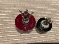
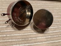
Here are a couple of pots that I have used in the past. One is 100 ohm, the other is 50 ohm.
Both are wire wound. The center tap goes to the top of your cathode resistor.
You can also just use a couple of 2-3 watt 50 ohm resistors from each AC filament to the top of the cathode resistor, but you won't be able to fine-tune it.
Both are wire wound. The center tap goes to the top of your cathode resistor.
You can also just use a couple of 2-3 watt 50 ohm resistors from each AC filament to the top of the cathode resistor, but you won't be able to fine-tune it.
Attachments
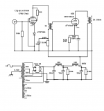
Here is the latest schematic. The EML 45B does not have a center tap, only 4 pins. 2 for heater, grid and anode.
Ok, connect G3 to the cathode on your c3g tube. Connecting it to ground will probably not hurt it but it might reduce gain. Its not like this in the specs sheet..
I think someone indicated this already, but your cathode should be around +87 Volts since you are doing "auto-bias" or "cathode-bias"
According to the emission labs specs for the 45b tube it looks like are trying to run the tube at 48mA.
so, this means with your 1.7K ohm cathode resistor, you want to measure around +81V at the top of it relative to ground.
IF you are measuring significantly MORE than +81V, then use OHM's law to calculate how much current your tube is passing as it might be TOO much.
In this case you will need to reduce your B+
Pay close attention to their Maximum conditions quoted by Emission Labs. Don't push it hard.
Running hotter will probably sound great, but your tubes will likely not last as long.
Still have that plate choke?
Ian
Team - progress! I did the following:
1. Per soulmerchant, connect G3 to the cathode on your c3g tube
2. inserted 2 x 56ohm resistors attached to the AC filament supplies (at the 45B filament pins). Tied the 56ohm resistors together and attached at the top of the cathode bias RC network.
1mV hum (undetectable from close to the speakers)! Yes!
45B output tube anode B+ 488V
45B output tube 49.5mA
C3g driver B+ 173V
C3g driver
Pat
Last edited:
OK, more measurements. Note, I am trying to hit the EML 45B recommended operating points (see attached, Yellow highlighted operating points).
1. 45B anode vs. ground : 475V. If the 1st C in the power supply is changed to 0.8mF instead of 0.68uF, then, according to PSUD, we get the extra 20V needed to hit the 495V target. Are there other ways to increase the B+ besides increasing the 1st cap in the power supply?
2. Top of Cathode resistor vs. ground : +83V
3. Top of Cathode resistor vs. 45B anode : 391V
4. 45B current still running at 49.5 - 50.0 mA. Is this too hot? I would like 48mA to match the recommendation from EML. What would I change to hit this target?
5. C3g driver Anode B+ = 170V
Attachments

Update: things are settling down nicely. The 45B is running at 48mA, which is the target.
My power up sequence is as follows: 1) heaters for about 1 minute 2) B+ When this sequence is followed and signal is already coming thru the input jacks, there is a "pop" (for lack of better words) when the B+ is applied. It's an all or nothing B+. Wondering what causes this and is there a way to stop it from happening?
Also, there are random (not frequent, but enough to scare the **** out of me) "pops" that occurs. Not sure why this is happening.
The pops that I described above are causing the rectifier tubes to go bad. I've lost 2 Type 83 rectifiers. Something is amiss. Thoughts? Filament voltage is 4.8V which is within the 5% margin of error. The power transformer is putting out 500V which appears to greater than the 83's max AC Plate voltage per plate with a capacitor input. If I eliminate the 0.68uF 1st cap in the PS, then the 83 has a max of 550V per plate, which should serve us well. I will remove the 1st cap in the PS and report back.
UPDATE: I removed the 1st cap in the PS (0.68uF) and the amp still pops and will likely blow my 3rd and final 83 rectifier. What would cause this "pop" sound? It also occurs when the B+ is either turned on or off. hmmmm. thoughts?
UPDATE: I removed the 1st cap in the PS (0.68uF) and the amp still pops and will likely blow my 3rd and final 83 rectifier. What would cause this "pop" sound? It also occurs when the B+ is either turned on or off. hmmmm. thoughts?
Last edited:
add inrush limiter in-line with your fuse
CL-80 Amphenol Advanced Sensors | Mouser
When I heard pops ... it was tubes have gas ...
not sure if this is your case ???
CL-80 Amphenol Advanced Sensors | Mouser
When I heard pops ... it was tubes have gas ...
not sure if this is your case ???
Maybe you haven't pre-heated the rectifier tube for long enough when initially installed - to ensure any free mercury that has jostled around the innards during transport/storage has vaporised, or if your ambient temperature is relatively low.
I'd highly recommend installing a secondary side fuse in each HV winding arm, and inserting 3x series connected 1N4007 in series with each rectifier plate as a form of PIV arcing prevention and likely rectifier failure.
I'd highly recommend installing a secondary side fuse in each HV winding arm, and inserting 3x series connected 1N4007 in series with each rectifier plate as a form of PIV arcing prevention and likely rectifier failure.
- Status
- This old topic is closed. If you want to reopen this topic, contact a moderator using the "Report Post" button.
- Home
- Amplifiers
- Tubes / Valves
- Help please: Bias and hum