I'd highly recommend installing a secondary side fuse in each HV winding arm, and inserting 3x series connected 1N4007 in series with each rectifier plate as a form of PIV arcing prevention and likely rectifier failure.
Thanks for the recommendation. Would the 1N4007 come before or after the rectifier tube?
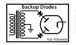
Is this what you were suggesting, trobbins? From valvewizard.com
"If we were worried about running a valve rectifier too close to its maximum Va(rms) [AC voltage rating], we could place one or more silicon diodes having a much higher peak inverse voltage in series with each anode, as protection elements. In theory, the valve rectifier can then be used with supply voltages up to twice the rated Va(rms). The silicon diodes will have no adverse effects on the normal operation of the valve rectifier."
So, if I am reading this correctly, this technique allows a lower rated tube rectifier to be used. I am thinking of the Type 80 instead of the 83. This eliminates the need to pre-heat the mercury in the 83. The 80 has a 350V Va, which would be sufficient as this technique would increase supply voltage to 2 x 350 = 700 / plate. Correct?
Attachments
Last edited by a moderator:
There is no free lunch.
If you disregard the regulations, the tube will die.
OK, back to the 83. Does the attached schematic look correct for use of the backup diodes to help with the "pop" issue that is causing the 83s to die?
Attachments

You push the boundaries.
The series diodes don't help with that, because the reason of dying not only the over voltaging.
IMHO 83 is too "tiny" for this job.
I regularly use mercury vapor rectifiers, but within the limits (not more than 80%).
My AX50 tubes are more robust ones than 83, but not "all purpose" devices.
If I wan to use rectifier tube over 500V, I choose kV capable tube (for example Tungsram PV200-1000).
83 datasheet is laconic to AX50 datasheet.
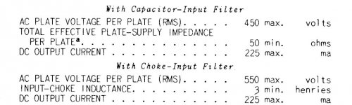
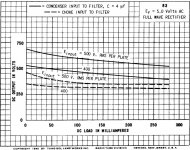
Minimum inductance (at choke input case) is only one parameter, if you don't understand devices behind it, it's meaningless.
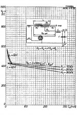
As you see, the AX50 define relatively small capacitor value after choke.
If you don't wait to total vaporisation of mercury (if my amp has not been turned on for days, the vaporisation time even 20-30 min!!, the "normal" heating time is 5 min), or switch back power in a short time after switch off, the MV rectifier will die.
The series diodes don't help with that, because the reason of dying not only the over voltaging.
IMHO 83 is too "tiny" for this job.
I regularly use mercury vapor rectifiers, but within the limits (not more than 80%).
My AX50 tubes are more robust ones than 83, but not "all purpose" devices.
If I wan to use rectifier tube over 500V, I choose kV capable tube (for example Tungsram PV200-1000).
83 datasheet is laconic to AX50 datasheet.
Minimum inductance (at choke input case) is only one parameter, if you don't understand devices behind it, it's meaningless.
As you see, the AX50 define relatively small capacitor value after choke.
If you don't wait to total vaporisation of mercury (if my amp has not been turned on for days, the vaporisation time even 20-30 min!!, the "normal" heating time is 5 min), or switch back power in a short time after switch off, the MV rectifier will die.
Attachments
The random 'pops' may be internal 'arc back' within the rectifier tube. Is the heater voltage correct for the spec (ie. within say +/-5%)? Have you tried to use a longer pre-heat time - say at least 2 minutes? Is the local ambient between say 20-40C ?
If the local ambient is below 20C then you may need a longer pre-heat time, as the outside glass temp near the base needs to reach at least 20C.
On the other hand, is the local ambient getting too hot, such that the outside glass envelope temperature near the base is getting higher than 60C ? That will cause internal gas concentration to get too high, and PIV will fall and that may be also causing arc-back.
Arc-back is typically associated with too high an internal gas concentration, but you may also have too high a secondary voltage - have you measured the winding rms at 500-0-500V?
Adding 'back-up' diode as shown in your last post effectively stops arc-back, as the external diode experiences the inverse voltage and stops any reverse current. The external diode has to withstand 1.4kV with some margin (margin for a higher secondary voltage, and margin because you are using multiple diodes in series). I recommend using three 1N4007 (from the same batch) in series.
How do you know your other 83's have died?
euro21, the OP's amp has a 50mA idle, and the maximum dc current draw is unlikely to get above about 100-150mA.
What the OP hasn't done is to provide a PSUD2 simulation to confirm the peak plate current doesn't exceed 1.0A during energisation of the supply.
What the OP hasn't done is to provide a PSUD2 simulation to confirm the peak plate current doesn't exceed 1.0A during energisation of the supply.
The RGP02-20E-E3 is a low cost 2kV 500mA diode, available at Mouser and the like. Takes the worry out of series-string diodes. Use two in series, if you want to be extra certain!
https://www.mouser.co.uk/datasheet/2/427/rgp02-1767948.pdf
https://www.mouser.co.uk/datasheet/2/427/rgp02-1767948.pdf
I purchased some RGP02-20E-E3 diodes and CL-80 Amphenol Advanced Sensors. They should arrive on Friday. Will report back then.
Thanks again for your input. Very much appreciated!
FYI: While the amp was running (prior to loosing the 83s), it sounded very good. Only one of the monoblocks, but still. Very promising.
Thanks again for your input. Very much appreciated!
FYI: While the amp was running (prior to loosing the 83s), it sounded very good. Only one of the monoblocks, but still. Very promising.
If you’re putting diodes in series with the rectifier tube you might as well do away with the tube. As others have said mercury rectifiers need long warm up times, especially if they have been sitting. Run the filaments for an hour if the tubes haven’t been used.
What the OP hasn't done is to provide a PSUD2 simulation to confirm the peak plate current doesn't exceed 1.0A during energisation of the supply.
The OP began to build amplifier (from very expensive parts) without knowing enough information using mercury vapour rectifiers.
I have been using amplifiers with MV rectifiers for years, but I use 4 independent power switches in my amplifiers:
1.) main switch, which switching all transformers primary to mains;
2.) MV rectifier/s/ filament transformer/s/ primary main switch;
3.) each other tubes filament transformer/s/ main switch;
4.) HV secondary CT switching to "ground": isolating MV from PSU.
Power on sequence in this order.
Main switch, MV filament switch, waiting ....waiting ....when mercury evaporates switching all other tubes filament (if you use DH tubes, is important "preheating" tubes before B+), waiting some seconds, then switching HV CT switch.
Using this mode the MV rectifier preheated correctly (requires a little practice), and NEVER sees excessive loading without preheating.
Before correct "heated" status ANY load (EVEN an unloaded smoothing -LC or CLC- part of PSU) may damage MV rectifier (sooner or later), so break switch between MV rectifier and PSU is NEEDED.
The other possibility for MV rectifier: when operating (HV switched on), MUST ALWAYS loaded! If you not sure, that load (amplifier) always drains enough current to grant "arcing" MV, use any ballast (high wattage resistor).
Myself have a simpler power on sequence : ON
power off is the opposite : OFF
(The gear has a mixture of Si and tube rectifiers.)
power off is the opposite : OFF
(The gear has a mixture of Si and tube rectifiers.)
A pot without a couple of "catch" resistors from the pot ends to the wiper, will give trouble if the wiper lifts (opens).
Correct! Thanks for noting this as well.
Myself have a simpler power on sequence : ON
power off is the opposite : OFF
(The gear has a mixture of Si and tube rectifiers.)
Yes, best solution. Also one I employ.
I use silicon diodes and TV damper diodes in a "Graetz" bridge. I do use a HT fuse as well.
No poisonous mercury in my home please. Disposal of mercury is a headache too. Proper disposal of Lead was hard enough for me!
One ON/OFF switch is the best for my daughters and wife to operate too. 😉
Still trying to get at least one daughter interested in this hobby... at least they like dad's vinyl records. 😎
A couple of updates:
1. I have my 83 tubes ready to reinstall once the diodes & inrush limiter arrives on Friday.
2. Also, I purchased a pair of 5Z3 rectifiers which have more voltage capacity.
3. The 45B filaments are using a pair of 50ohm resistors without a pot. Measures 1mV of hum. Very pleased with this.
4. the "pop" noise occurs not only when the unit is turned on/off, but also at random times while listening to music. Not sure why this occurs when listening to music, but this is when the 83 tubes have blown. Thoughts?
FWIW: I do let the 83 filaments warmup extensively (15-30 minutes when first installed). Then, upon reuse, the filaments warm up about 1 minute prior to turning on B+
Pat
How do you determine an 83 has 'blown' ?
Have you measured the 500-0-500Vrms levels, or just taken them as granted?
Does the heater voltage measure at 5.0Vrms ?
Have you measured the 500-0-500Vrms levels, or just taken them as granted?
Does the heater voltage measure at 5.0Vrms ?
trobbins: here are the measurements that I used to determine if the 83 is blown:
the heaters measure 5.0V
B+ into the 83 is measuring 500-0-500
B+ out of the 82 is measuring 0-0-0
Dead 83.
the heaters measure 5.0V
B+ into the 83 is measuring 500-0-500
B+ out of the 82 is measuring 0-0-0
Dead 83.
Thanks for that.
Assuming that heater current is flowing, and that there has been no loss of internal gas concentration, then it seems like the failure mechanism is the cathode has substantially reduced emission. I guess that could be a result of gross arc-back current levels damaging the cathode surface - which would be a one-way street as any initially good cathode surface would have to handle an increasing current concentration.
Assuming that heater current is flowing, and that there has been no loss of internal gas concentration, then it seems like the failure mechanism is the cathode has substantially reduced emission. I guess that could be a result of gross arc-back current levels damaging the cathode surface - which would be a one-way street as any initially good cathode surface would have to handle an increasing current concentration.
Last edited:
trobbins: here are the measurements that I used to determine if the 83 is blown:
the heaters measure 5.0V
B+ into the 83 is measuring 500-0-500
B+ out of the 82 is measuring 0-0-0
Dead 83.
Have you checked for continuity through the filament to see if it's getting blown? It seem like that is what is happening if you don't even have 1/2 voltage. Do you see it light at all?
Last edited:
- Home
- Amplifiers
- Tubes / Valves
- Help please: Bias and hum