Kitchen Cabinet Speaker

We have a Pure Evoke 1 DAB/FM radio in the kitchen and the sound from the the built in speaker is not up to much.
The radio lives near a tall larder unit made of 18mm faced chipboard with slide out wire baskets and containing dried and tinned foods. For a quick and easy solution I was thinking about cutting a hole in the side of the cabinet and fitting a HiVi M3N or similar and driven by a class D amp.
Is this likely to work?

Lance

Newbie Gainclone Problems (LM3875)

This is my first post. I apologize in advance for my extreme ignorance.
I recently bought an amp that I thought might be a shortcut to gainclone fun. See first picture. It cost less than a bare toroidal from partsexpress.
My goal is to build something like what's in the second picture.
I don't yet read circuit block diagrams well, so I hoped that by starting with a complete amp, I could just connect up an eBay input selector and be done (in a new chassis).

However, this amp has some hiss, and when I check the voltage at the amplifier, I read 45.7 volts. Am I right that this is too much power? The transformer has 30 volt secondaries.

If I'm right, should I try to modify the psu to drop the voltage? Or buy new amplifier boards? (e.g. ebay mx50se)?

Thanks for your help, and my apologies if asking questions like this straight off is not ok.

Attachments

  • DSC00252.jpg
    DSC00252.jpg
    783.8 KB · Views: 540
  • DAL3886INT_6T__46364.1426966809.1280.1280.jpg
    DAL3886INT_6T__46364.1426966809.1280.1280.jpg
    46 KB · Views: 514

Wrong transformer

In my limited electronics design experience, I've been doing digital for decades. I've just acquired an interest in tube amplifiers, and analog circuits in general. As all of you know this is far more intricate than digital.

One easy thing for someone like me is to forget about PP vs RMS. I ordered a Hammond transformer from Digikey that, with a CLC without load outputs around 530Vdc.

I was originally modelling around 375Vdc for B+.

I was planning on working with some 12AX7s and KT88s. I know the KTs can handle it, but definitely not the 12AX7s.

I've bought Merlin's and Morgan's books and understand the predicament I'm in, particularly around the DC load line and if the cathodes aren't heated up, and voltage drops that come with that. The KT88s should be fine but the 12AX7 would not appreciate a 530Vdc potential.

I'm also using silicon diodes as a rectifiers, so there is no heat up delay.

I basically bought the wrong transformer, I meant to get one at a much lesser volt.

I realize there are many ways I can approach this, including just buying another PT, setting up a delay circuit, etc.

In my mind, based on what I've learned, I'm already screwed. A 12AX7 has a max plate voltage of 300V, assuming no current flow. With the PS I have I'm far in excess of that, no matter what I do.

I'm just wondering if anyone can suggest the most economical and safe way to move forward, just to get by, while I refine my schematic, without buying a new PT. I've already learned(re-learned) a few lessons, which is why I'm asking for more knowledge.

Bottom line - how can I continue testing with this circuit and guarantee that I won't overvoltage my 12AX7? Did I blow it with my ill transformer choice or is there a way around it?

FS: DIYINHK AK4497 DAC Boards

I have realised that I am not going to get around to assemble this dual mono DAC that I had planned so I am putting these up for sale.
These are 2 no PCB's as per the link below that I build a little while ago.
768kHz/32Bit AK4497EQ DAC, I2S/DSD input - DIYINHK
Selling both boards together for half new price at £99 excluding PayPal fees if appropriate and postage.
6E479551-90FD-4A20-9705-BC60A6114231 by themystical2012, on Flickr
996D75FA-3BE0-474D-AE7A-C7641E5A6B51 by themystical2012, on Flickr

3 way with TC9FD as mid -suggestions

Have been reading a lot of good reviews about Peerless TC9FD as a mid and about how the voicing is perfect and response is flat .
I am interested in a 3 way with TC9FD as a mid with a minimum of 8-10 or at the max a 12 inch woofer in a relatively small enclosure . Can some one point out any plans or builds which I might have missed ?
I did read a 5.5 inch tangband sub build , but the goal is to have an all rounder with a decent spec woofer and a tweeter implementation . The target cost would be under 300 USD for the drivers .
I am not good with speakers and crossover design so I am at this point of time looking for open source builds .

Any suggestions ?

Questions regarding designing a parafeed line stage and the LL1930 transformer

Hi, I am new to the hobby and have been working my way through books and articles and learning to use LTSPice.

I am interested in designing, simulating, and building a parafeed line stage and have been looking at the Lundahl LL1930 transformer for parafeed line stage applications. I was wondering if anyone has built a line stage using this transformer.

The transformer has two primary windings and two secondary windings with a 5.1 : 1 or 11.6 : 1 turns ratio and. Static resistance of each primary is listed as 610 ohms and the static resistance of each secondary is listed as 16 ohms.

I do not see a listing for the primary impedance however, and I am wondering what tubes are recommended for use with this transformer.

More generally, I would also be interested to learn about the thought process you use when designing a new amplifier/preamplifier from a systems perspective. Do you begin with a circuit topology and then pick a transformer and work through the circuit backwards optimizing as you go, or start from the source and work towards the output, or use another strategy altogether. Many thanks, Martin.

Ian's Ultracapacitor Explore PLUS - build thread

This thread is for the owners of Ian's excess PCBs from post 163 of his original thread Develop ultra capacitor power supply and LiFePO4 battery power supply.

The schematics were shared in post 187.

I started a Project in Mouser: Ian Ultracap PSU v1. I chose the smaller-capacity alternative as the ESR was lower too and I'm not sure I'd need that much capacity anyway. Please adjust the project accordingly, if you need the higher-capacity alternative.

The outstanding part is the LT3042 board. I will update this post when we agree which one to use. So far, there a few ready-made eBay alternatives (though with LT3045 instead and Ian warned me that we should make sure the current is limited to 200mA) and some PCBs were designed by diyaudio.com members and can be ordered from PCB manufacturers.

The list will grow here:
1. PCB: LT3042 LDO Regulator - PCBWay.
2. PCB: Ultra Low Noise Linear Power Supply, using LT3042 - OSH Park.
3. LT3045-78xx Ultralow-noise (0.8µVrms) linear regulator 0V-15V, 0.5A, 78xx Layout - eBay
4. This one is also pin-compatible, but it doesn't look as good as the one before it: LT3045 3.3V 500mA 0.8uVrms Ultra Low Noise Linear Voltage Regulator Replace 7833 - eBay

Technics SE- A900S no speaker relay click

I have been asked to have a look at a friends amp
the amp powers on and the vu meters light up but no relay click
the operation light is not lit
you can hear the big power relay click on and off
the main power supply is working both caps test ok
i have had the board out and checked all the caps replaced two which where out of spec
replaced caps C502 / C504 100uf 6.3v and R502 which was burnt
put it back together and still the same but when switched on R502 gets very hot
i have included the manual
TECHNICS SE-A900S SERVICE MANUAL Pdf Download | ManualsLib

20200718_153233 by glenn jarrett, on Flickr20200716_152600 by glenn jarrett, on Flickr

MLSSA on linux?

Are there loudspeaker measurement systems based on MLSSA principles around? For measuring inside it might be better then swept sine.

I had something like that running on DOS with an interface connected to the printer port years ago. But I guess now using the sound card might be a better option 🙂 I'm happy if I can do frequency response, impulse response and waterfall.

Hello from Germany


Hi, I'm new to the Hi-Fi world and I love to learn things. I've been considering investing in a Hi-Fi system for my desktop and my living room alike. I figured: why not do everything by myself? I have time, am patient and unequivocally wish to enjoy the process of searching for the right parts, understanding how it all works etc.

Any advice for a neophyte like me ? 🙂


I only have a pair of Focal Spirit One S Headphones on my desk... hopefully it'll soon change with your recommendations (i.e. DAC, AMP, Speakers...): I'm open to any suggestion. Where should I start ?


Thank you for reading this!

light up tubes without signal

I know this might sound strange, but I want to power tubes only to light up, I don't need to amplify any signal.


I have two cheap EL34, from the datasheet

Filament Voltage 6.3V
Filament Current 1.5A


A) I presume that in order to power both of them I need a transformer with 6.3V secondary and 3A in total. Am I correct?

B) Is AC ok? Or, do I need to provide DC voltage?

C) I have been told that doing this way the tubes won't last that much? Is this True? How long they can survive?


I know this is kind of strange, but I need this to make a terrible joke to a bunch of bad audio-friends.

DIY Amp Guidance

I am very new to the idea of building an AMP. I have an old metal toolbox from my Grandfather that the electrical union gave him with a nameplate. I just can’t bring myself to throw it away. So I have this idea of making an amp out of it. The tool box is roughly 18x8x9 in size and is a metal Craftsman.

I found a MOD 102 5 watt amplifier kit on Amazon. I would like to add 3” or 3.5” speakers to the front of the tool box, I may be able to get 4” in but it would be tight, and start detracting from trying to keep a more nostalgic look.

I have no idea what I am getting ready to step into. I am very handy and the project itself does not scare me. I just haven’t done audio before with such a specific purpose/outcome. Success would be a unique conversation piece that I could plug into and get a decent sound out of to strum around with an electric or acoustic-like a little practice amp.

All guidance and direction appreciated. Thanks in advance

Jordan Eikona as a mid

Just curious, anyone used the Jordan Eikona as a mid in a 3 way. This lauded as one of the best full rangers and can dig to 40hz in the right box and touted to have “holographic imaging qualities” (puts the BS Dictionary away!).

Looks like it could do 150hz to 5khz in a 5l sealed box supported by a 10” (sub) woofer (e.g. SB29NRX75-6, Scanspeak 23w4557, Dayton RSS265HF-4, L26ROY) And a small ribbon, 0.75” tweeter Or Fostex Supertweeter (e.g. Neo CD1.0, OW1, T90a).

However, not seen any off axis measurements so a bit of an unknown.

Thoughts?

Speaker for analogue synth

I'm playing around with analogue synths and I'm considering whether or not to build a dedicated speaker (or two). I figure there have got to be a few people here who have done similar things.

I have a few requirements. If im going to go to the trouble then it should be able to handle practice volume with other musicians. It should be able to reproduce low notes in the range of 20hz (give or take depending on whats realistic), and it needs to be able to reveal the appealing timbres and complexity of a genuine analogue synth. I'd like to keep this under apx $200/speaker but thats a ballpark.

Id prefer not to build a horn but I'm open to suggestions.

Amplification will be some sort of off the shelf thing like a behringer or similar. Active is an option or I can design a xo. I have measurement gear.

Left to my own devices I would likely look at Eminence's 12" pa drivers and a compression horn but I was wondering if anyone has used something like this that they were super pleased with.

DIY full range speaker

Hi i am trying to get the knowledge and build a simple full range speaker floor standing, something very easy (no spl metering , no crossover designs etc) . I don't have any wood work skills or a friend so i will go to a wood work shop with the dimension of my floor standing dimension from a cabinet speaker calculator for the specific Full range driver .

Is there any links related to a such a simple project ? Because every link i found was to complicated for what i am trying to do .

For example i want to buy a Tang Band or seas or scanspeak driver hook it up to a floor standing sealed cabinet (made by the wood worker) with the right VAS lts , damp the box with dumping material and then connected the speaker to a Amp and play some music .
I currently have speaker, POLK AUDIO T50, so i will have some reference of the sound .

Could a such simple project end up with a good sounding experience overall ?

Need assistance on this resistors found in KAV-300IL

I bought and old KAV-300IL. Open up the amp and found this repairs done. Its 2 x Dale 5ohm resistors soldered across the 10ohm AMD resistor. I don't quite understand whats it for. Because 10ohm dale and 10ohm SMD resistor in parallel would become 5ohms. Found it across 3 10ohm SMD resistors....


would need some assistance on whats it for??

Attachments

  • resistor.jpg
    resistor.jpg
    488.3 KB · Views: 183

Do Brands of Capacitors Matter alot for Power Capacitors?

I am planning to replace the 8 x 6800uf 63V capacitors on my amp as they are 20yrs old.....


I am curious if brands of capacitors matter. The original ones are nichicon ones. But if I use brands like cornell dubilier, Kemet, united chemicon, will there be any significant difference in the audio?


I do understand mundorf is good but its very costly so I am looking for alternatives.

miniDIGI Jumper config for 1 miniDIGI + 2x miniDSP

Hello.
I don't know if this is the proper forum, but let's try:

I do have a stack with 1 miniDIGI board + 2 MminiDSP balanced connected following the Application Note "Configuration of 1 miniDIGI + 2 miniDSP" to buils a 4 way crossover

What I need to confirm is the Jumper Chart for 1 miniDIGI + 2x miniDSP stack because i think thet the one ath miniDSP web is wrong or, at least not the proper one for my application.

this is what I did:

Minidsp 1 (left CH) SLAVE
Minidsp 2 (right CH) SLAVE
Minidigi MASTER

Does I have to setup J1 at miniDIGI like a 2 way setup??

An externally hosted image should be here but it was not working when we last tested it.


Picture might not be cclear, but the miniDIGI setup is like MASTER

Bullet-shaped BR

I was CAD doodling yesterday and came up with a rather sleek-looking bass reflex for the Tectonic TEBM36S12 that can be printed in a single piece (though it will need splitting up to fit out). The part I can't quite figure out is where to put the connectors and what form the stand should take. For the stand, a profile that joins on at the front would allow it to be printed with the speaker without using supports. I would really appreciate examples of anything similar which I could s̶t̶e̶a̶l̶ adapt for this design. The only thing slightly similar which I could find is the top half of the B&W Nautilus.

On the driver front, could anyone suggest a decent sub-£100/pair driver that's less than 100mm outer diameter? I'm not set on using the Tectonics, I just had them to hand for another project and had the parameters plugged into Transmission Line.


Thank you.

Attachments

  • BRSq CS.JPG
    BRSq CS.JPG
    222.5 KB · Views: 239

Arcam AV50 Receiver red power LED

Hi everyone, i have a AV50 prologic receiver which just powers on and the power led goes from amber to solid red, there's no flashing red. There is nothing on the LCD display. I've also tried to press different buttons to "wake it" but no response.

Is there someone who knows what this solid RED led means? I've emailed ARCAM and they actually said they don't have a specific fault for this. I'm requested a service manual from them.

Unforuntately i don't have the remote anymore, so can't do any troubleshooting with that.

Thanks in advance.

Guitar amp with 2 x EL86 push-pull

For some time now time i've been planning to make a guitar amp with 2 x EL86 (= 6CW5) push-pull.

I looked at the schematic of the Hagström 620, which has 2 x EL86 in push-pull but i do not trust the schematic i could find on the internet. The screengrids are being fed straight out of the rectifier section, while the anodes are being fed from a point after a fuse and a resistor. I can hardly believe this to be right. If that fuse would blow, it would probably take the EL86's with it.

Because i allready have built a guitar amp with EF86 + 2 x ECL86 pp which is based on the clean channel of the VOX AC15, i now want to build a similar amp with EL86's, so i can hook the two amps up in stereo.

According to Philips datasheets, two EL86's in pp can produce 18,5 Watt at 4,5 % distortion, with Vba = 250 V and Vbg2 = 200 V.

Because the current for the screengrids varies a lot between no signal (2 x 2 mA) and full signal (2 x 13 mA) i plan to stabilize the screenvoltage with 2 ZZ1040 voltage stabilizer tubes.

I want to use the E92CC as the phase inverter because of the chassis i plan to use. The schematic for the phase inverter comes out of a Philips datasheet for the ECC40. Not exactly the same tubes but i am pretty sure it will work with an E92CC.

So here is my plan. I am a bit unsure about the 100K resistor that is connected to the point where the two ZZ1040 are connected to each other. I think this resistor is necessary for making sure that both ZZ1040's will start up.

Any suggestions?

Attachments

  • Hagström 620.jpg
    Hagström 620.jpg
    192.3 KB · Views: 525
  • Schematic.png
    Schematic.png
    30.7 KB · Views: 539

Suggestions for complete newb - PC/desktop speakers?

Hi all,
I've done a fair bit of searching and reading, and all this sounds more like algebra than English to me, so I hope this isn't a lost cause.
I'm trying to get some help to repair my old Logitech Z-5500 PC speakers in another thread, and something someone said kicked off a curiosity bug in my head about speaker building.
So I started researching and now I really want to build myself a set of small deskop speakers to replace the Bose bookshelfs that I'm using now.

I really like the Needles, I just don't have the room for them in my office, and they will need to sit on my desk, not on the floor.
I have a decent workshop, so the actual box construction shouldn't be too hard, and I can usually solder without burning down the house.
My problem is that I have not a single clue where to start in regards to driver selection or enclosure design, plus I'm cheap (read: poor) and don't have a ton of extra time for a lengthy build.
Where should I start? I'm looking for something that will sound as good or better than my Z-5500s with these Bose bookshelf speakers (sorry, can't find a model number) serving as the left/right channels. I'd also like them to be smaller than my current boxes, which are about 15"tall x 10"wide x 7"deep.
I'm driving all this off the Z-5500 amp and sub, which I plan to keep unless there's a compelling reason not to?

Any advice appreciated!
-Mike

As simple as possible, no simpler?

I'm fishing about for something to build with the parts i've collected and need a decent MC phono amp. After some research, i'm interested in this. Thanks to Richard Lee for the front end and an unknown Sony engineer for the back. Any comments? Improvements?

SonyPhonoMC-noise.png

SonyPhonoMC-raw_response.png
If i simulate an inverse RIAA circuit on the front, i get a mild bump around 30Hz and rolloff below and a very small rise at 20kHz, otherwise flat.

TIA, Rex

Attachments

  • SonyPhonoMC-Noise.JPG
    SonyPhonoMC-Noise.JPG
    126.9 KB · Views: 173

Yamaha P3200 - IC replacement

Hello! I'm looking for a suitable replacement (or upgrade) for M5238A input op amps in my Yamaha P3200 that I recently bought. It seem that both of them are fried. Will OPA2134PA work?
The amp will be used in my studio to power my main monitors (Tannoys), so if there is a possible upgrade I am into that!

I've attached the P3200 schematic if needed.

Attachments

XLR low pass filter between prepro and power amp

I'm not sure if this is possible (I'm a complete beginner) but is it possible to filter out frequencies above approximately 30khz between a preamp/prepro and power amp?

The prepro is listed as 560 Ohm at the XLR output
The power amp is listed as 47 KOhm at the XLR Input

This looks useful but I'm unsure which resistance to use or if it is even suitable:
Low Pass Filter Calculator

Acurus A150 LOUD Speaker Buzz

My Acurus A150 which I’ve had and used without any issues for more than 20 years with the Acurus surround processor preamp and another 3 channel Acurus amp suddenly began producing a loud buzzing in the speakers. It happened last night when watching something that went from fairly low volume to high volume. The buzzing is LOUD. Even with the lines in from the preamp removed the buzzing continues. It’s not the low hum you might expect from a ground loop issue. I’ve swapped speakers to make sure I hadn’t blown the pair. The buzzing is still there. Before I take the system apart and do a rebuild I figured I’d ask if anybody has seen this issue or something similar on an Acurus amp or others.

Hypex Ncore NC400 - input anti-alias filter?

A friend brought me a pair of Hypex Ncore NC400 little amplifiers to make some deeper analysis, based on my measurements. First, I would like to congratulate Bruno and the team to outstanding parameters of this amplifier in the audio frequency band. Very low noise (I measured -95dBV(A) at the output, negligible distortion of all kinds, no hum, no mains spurious components. So far so good. I was thinking about returning the amplifiers to the owner saying I have found nothing special. Then I got an idea to use old-fashioned stand-alone instruments and to make some measurements like long ago in the lab. I have connected an analog 10Hz – 1MHz generator to the input and observed amplifier voltage output shape on the scope screen. Everything fine up to 440kHz. And then it happened – though the input signal was only 21mV, it started to be evident that the amplifier, at least the piece that I have measured, has not designed an input anti-alias low pass filter properly. When the input frequency approaches to Fs (about 460kHz) and 2Fs (about 920kHz), one can see aliases, difference frequencies Fs – Fin (or 2Fs – Fin) appearing at the output of the amplifier. I measured about 56mVp-p output swing of the alias signals, in the audio band. I have put a 2xRC analog low pass filter (27kHz) at the scope input to remove 460 kHz switching frequency of the NC400. So, the input signal containing HF components may, under certain circumstances, create audible alias frequencies at the NC400 output. This is not very good and I guess that a better input anti-alias low pass analog filter would cure the situation.
Attached is my measuring place, the alias signal is stored in the scope memory. Please see analog low pass filter at the scope input to remove/reduce 460kHz switching frequency.

Attachments

  • Hypex alias.JPG
    Hypex alias.JPG
    246.8 KB · Views: 781

Whats the Main Purpose of Using Multiple Low Power Transistors in Parallel?

Hi all, I am wonder what the purpose of using multiple Low Power transistor in parallel.

Just an analogy. For 200W, I use 4 x 50W rated power transistors. Is it any better compared to using 2 x 100W ones? I am asking because I saw 6 pairs of Sanken A1860/4886 on the Krell 400xi. Each pair is rated at 80W. If they use higher power variants, it will cut down the number (eg. 4 pairs of 130W rated ones).

So, is there any reason to use more transistors??

Monster Massive

In this thread I'm going to take another stab at building a Synergy Home for my home. I've built some Unity horns for my car, but have never finished one for home use. I had another project that died on the vine about a year back, and this project will attempt to address some of it's shortcomings.

Here's some things I hope to accomplish with this project:

1) From my car projects, I've learned that using existing boundaries can allow one to make horns much much smaller than what would be "ideal." The typical solution is to use the corner of a home. I have tried corner horns, and I do not like the 'headphone' effect. Basically corner horns have no reflections, and that makes them sound a bit uninvolving, like a giant set of headphones. But there's another way to use boundaries which will be utilized in this project.

2) I really think that Geddes is on to something with his research that indicates that diffraction and higher order modes are two of the things that make horns sound bad. At the same time, these things can be problems in Synergy horns, because of the midrange taps and a lack of termination on the horn.
An externally hosted image should be here but it was not working when we last tested it.

For instance, the old Lambda Unity horns may suffer from diffraction at the edge of the horn, and in the horn throat at the midrange taps

3) The last thing is cosmetics; my reference speakers are currently banished to my bedroom due to their size. So I'm hoping that this project will have a smaller footprint and also a look that's avantgarde enough to make it back into my living room.

TPA3250 anywhere?

Hi,


I was planning to build the nice little amplifier described by Glenn Zorpette at IEEE Spectrum (Full Page Reload), however as he and others have noted, the 3e-Audio amp module does not seem to be available any longer. I have looked briefly at the long thread on here about amps containing this IC and searched online, but I have seen very little that might work as a good replacement.


Does anyone have suitable ideas for substitution? I am handy with a soldering iron and reading schematics, but I'm not really up to designing things from scratch. And having a decent premade PCB is a must!


Thanks,


Phil

Best resistors for F-5 and B1 mezmerize

Just curious what opinions are out there on the best resistors to use in these Pass builds. I’ve used PRP in the past in a Dynaco ST-70 build. With it being tube I’m sure it’s not the highest resolution, but I’ve read some less than thrilled reviews on them. So I’m thinking of trying out either Takman or Vishay/Dale. I’m liking the Takman, because they are cheaper, have both metal film and carbon film (the build threads show that carbon film is preferred in some places), and every value is available in the Takman. For whatever reason I can’t find a lot of common values in the Dale, like 220k. I can find 221k which I know it doesn’t matter, but some values the closest are even more off. This is with Mouser at least.

So just wanted to gather some thoughts before I place any orders.

Dan

Service Manual for RAMSA WP 1400

Hello guys! , i dont know where a post my thread, i think posted here.


I need e service manual for my RAMSA WP-1400 amplifier.

Last time i use them , all is fine sounds graets, but yerterday i power-on the amplifier and i dont know what pass , the sound is tooo slow and if i level up the gain . Makes the sound saturation. i try use other inputs (pc, cell phone) but nothing pass.

I discover a problem in frequency divider , i have one in each speakers. i replace frequency divider but the amplifier not returns to normal.

Can you help me please?

Thx

Sorry for may bad English.

An externally hosted image should be here but it was not working when we last tested it.


An externally hosted image should be here but it was not working when we last tested it.

6080 Hybrid Power Supply

I’ve been doing a lot of research in hybrid supplies, One because I have a large of tubes that are in this PS, and another because particular op amps are cheap, and usually you can get very good results. I also have an old Navy Electronics manual
And it shows a pentode tube driving a 6080 tube, and the pentode I happen to have a lot of is the 6CB6, so I went with these, and also I’m a big fan of Walt Jung! That guy knows op amps! Anyway here is my result, I’ve already built it and tested it works great so far, now listening tests are in order. BTW notice the 33K resistor coming to G2 from the regulated side, this is what I found in the Navy Manual, a small amount of feedback. A ripple reducer! Interesting!

One note: the trim pot is 100K not 200K

And lower resistor in divider is 6.98k and not 12K

Attachments

  • 84FB80C9-4FB6-4429-821F-FBDC7AA72DF1.png
    84FB80C9-4FB6-4429-821F-FBDC7AA72DF1.png
    793.5 KB · Views: 218

Mark Levinson 336 blowing fuses in home

Hi,

I have 2 ML 336 amps. One of them is blowing the 20 Amp fuses in my home when switching from off to standby. I found that there are 3 wire wound resistors inside, that I guess are used to slowly load the huge caps in this amp. These wire wound caps are defective. Anyone knows where to get them and what would be the specs of these resistors ? Thanks.

marantz pm17

T2 (tape2) play relay L309 and PH(phono) relay both have low voltages on the negative sides of the capacitors that are in parallel to the coil of the relays. This causes the relays to click constantly, the positive side is perfect and all (around 22v)

I de soldered both relays except for the two coil pins and the same thing happens, so not caused by an short after the relay. The coils measure ok. Swapped relay, replaced the two suspect caps, even though the ESR was good on them. Inspected solder joints under light and magnification.

Next measured the voltages on J103 and found flutuating voltages on the PH self biased transistor Q101 and Q107 for the T2 (play) Base ends & the corresponding chip pins LC7822, was getting
fluctuating voltages here too, irrespective if the PH or T2 were switched on or off. I replaced the self biased Q101 and this did not make a difference.

Are these chips know to go bad? Before I go replacing this, if I can even find one that is, has anyone any idea what else it could be
I have set up the dc offset and the transistor bias and they are both spot on, on both channels. The relays only seem to click when it gets hotter, after a few mins. I will get some freeze spray next week and try and
freeze the chip to see what happens. I have taken the power board out, inspected all solder joints, tested the caps with ESR meter.
Its an horribly complicated amplifier, god I Love my marantz 1030 and receiver 2216b they are a pleasure to work on. It would be handy in the marantz repair shop, just swap in a few new boards.

Attachments

  • marantzPm17-2.jpeg
    marantzPm17-2.jpeg
    98.6 KB · Views: 242
  • Marantzpm17.jpeg
    Marantzpm17.jpeg
    106.9 KB · Views: 258

I killed my FRD with a fancy cabinet - Help!

Hello DIY audio,

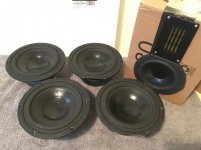
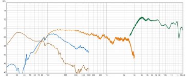
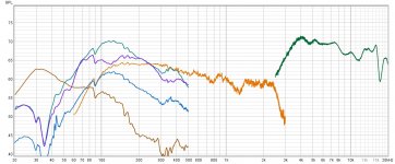
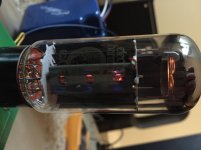
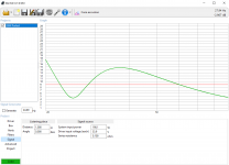
Ok - i got this FRD and played around with it at home in some dummy/mock cabinets:
One thing that stuck out for me, was that this driver was easy to 'choke', with to much dampening - it hated dampening within the cabinet.

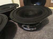
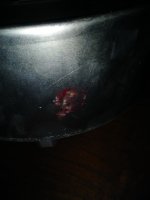
Visaton : SL 87 ND - 8 Ohm

RDC: 7.5 Ohm
Qm: 2.38
Qe: 0.91
Qt: 0.66
fs: 138 Hz
VAS: 1.24 l
mms: 2.1 g
cms: 0.63
rms: 0.77 kg/s

SL 87 ND - 8 Ohm | Visaton

aside from that it sounded good within my small listening room, i then contacted visaton and they recommended a 5L sealed cabinet, i could go bigger though - which suited my interest as i had an 8L cabinet that needed filling.

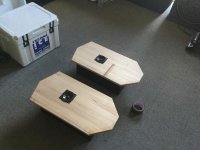
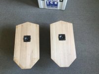
I built the cabinets and used no stuffing what so ever, but maybe i tested my luck and used a thin wool/felt lining glued within the interior walls of the cabinet.

I also made the Cab. walls and baffle of the cabinet extra thick. (1 inch)
Being a loudspeaker noobie, i thought some overkill wont do harm??

Well it did haha, so the drivers sound terrible within these cabinets - they sound muffled and acoustically dead. there is no sound below 500hz atleast...

So my pride is damaged - can i salvage this project from crash and burn??

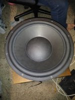
  • Recut the baffle for a bigger stronger driver (4 inch)? (recommend a driver!!)
    maybe the TS parameters have to be allowable for an over engineered 8l cabinet??
  • Experiment with porting? (cut a modest 1 inch hole in the baffle and with cardboard tubes, tune it by ear?) It will make it bass reflex, but the porting may allow it to breath??
  • Any other advise or ideas? I dont mind experimenting 😀


UPDATE -

Got some Extra drivers on order to try: Dont hesitate to recommend something it might 'whet' my appetite for another build 🙂


Mark Audio Pluvia 7 - Chrome

Pluvia 7 Chrome

Speaker Specifications
Nominal Size (mm) 70
Nominal Impedance (Ohms) 8
Power Rating (W) 22
Sensitivity 1W/1M (dB) 85.84
Resonant Frequency (Hz) 67.86
Qts 0.538
Qms 2.391
Qes 0.695
Vas (Litres) 5.543
Re (Ohms) 7.2
Xmax (mm) 4
Freq Response Min (hz) 70
Freq Response Max (hz) 25000
Mark Audio Pluvia 7 - Chrome
Brand: Mark Audio
Product Code: Pluvia 7 Chrome

Visaton Speakers in Kraut Jars on Vimeo

Attachments

  • sl87nd_8.pdf
    sl87nd_8.pdf
    86 KB · Views: 79
  • IMG_1360.jpg
    IMG_1360.jpg
    985.6 KB · Views: 473
  • IMG_1349.jpg
    IMG_1349.jpg
    981.8 KB · Views: 469

jbl 2226h - 30 Hz to 220 Hz - can do? max spl?

I am in India. These drivers have become accessible to me again. I have used them before in 4Pis... They were fantastic.

There must be many newer drivers that are better. I myself have a pair of AE TD15Hs, which are probably better. But the AEs are not available here, and by the time I have them shipped and pay the customs levies, it becomes nonviable. Now my cat has chewed the surrounds on my one of my AE and it is going to be too cumbersome to have them serviced to factory spec.

Can the JBL 2226H be used as a woofer in a 3 way system with -3dB points @ 28-33 Hz and 220 Hz (freestanding)? What would be the appropriate box and what is the maximum SPL I can achieve in a studio monitoring situation? I will be using DSP/active crossovers... MiniDSP or Hypex...

I have been playing with the attached .wdr file in WinISD, and coming up with all kinds of confusing plots...

I'd be very grateful if those of you that are used to doing this and understand the balance of compromises necessary, can play around with the wdr file, and suggest box/port/filter combinations which will help me achieve maximum SPL with my response criteria in consideration...

Thank you.

Attachments

CFP Unity Gain Buffer

I'm looking for a line-level buffer stage to precede a volume pot. The criteria are that it a) needs to run from the PA main rails; b) capable of driving a 1k pot; b) reasonably high input impedance; c) DC coupled input and output, with very low offset to minimise any DC across the pot track ends.

I've come up with the circuit below, which is reasonably simple and meets my requirements. Any suggestions before I commit to layout and assembly?

Edit; see post #11 for information about modern op amps capable of driving a 1k pot to line levels.

Attachments

  • cfp buffer.png
    cfp buffer.png
    17.6 KB · Views: 1,450

For sale: (4x) Vifa M18WO-09 8-ohm woofers

SOLD!
For sale: Four (4) clean, lightly used Vifa M18WO-09-08, 8-Ohm, 6-1/2 inch woofers.
The bad news: Two of them have a small section of the outer magnesium basket neatly removed from one edge (see pic), while the other two are unaltered.
Otherwise, it's all good news. These look great: cones, spiders, rubber surrounds, terminals, all very presentable, and measure the same 5.9-6.0 DC Ohms.

U.S.A. shipping only. Asking $90 plus actual USPS ground shipping cost for the set of four woofers as seen.

Attachments

  • Vifa M18WO-09-08 pic2.jpg
    Vifa M18WO-09-08 pic2.jpg
    119.7 KB · Views: 383
  • Vifa M18WO-09-08 pic1.jpg
    Vifa M18WO-09-08 pic1.jpg
    124.6 KB · Views: 342
  • Vifa-M18WO-09-08.pdf
    Vifa-M18WO-09-08.pdf
    102.5 KB · Views: 84

Fender tube vibrato circuit voltage weirdness

I'm working on a Blackface 1967 Fender Bandmaster AB763, and the thing that's keeping me from being done is there is some out of spec voltages in the vibrato circuit, hoping someone can enlighten me.

Link to schematic

When I turn off the vibrato switch, the 12AX7 is getting over 400V at the first plate (pin 1) and both cathodes show around 0V. The grids are both receiving around -40V.

Then when I turn on the vibrato, the cathode of the second section (pin 8) is showing around 18V, while the pin 3 cathode bounces back and forth between -1 and 2V.

Bottom line, the amp is sound good and the vibrato is working, I just don't know a lot about these circuits and I'm not sure if this is just fine. 400V seems a bit high to me. The 220K resistor got replaced and it doesn't seem to do much to drop that voltage to 280 where it belongs.

Any help would be appreciated.

Max

Virtual Waves anything similar?

INRP TECNE - site informatique, physique et musique (analyse de logiciels : Virtual Waves)
I had this french software in 1996, It came on single diskette. It has a wonderful graphical synthesizer construction by wiring modules , that I simulated active crossover filters and listened though input output wave files. It has signal analyzer of .wav file that I used the 3D to measure response of horns distinguishing from room reflections.
This software in not available any more, Is there anything similar with affordable price?
Hayk

15" Mystery woofer

Does anyone know anything about this woofer. It is double spider Numbers on it are 117V and 050324.

Attachments

  • 20200716_174613_resize.jpg
    20200716_174613_resize.jpg
    108.8 KB · Views: 248
  • 20200716_174623_resize.jpg
    20200716_174623_resize.jpg
    50.8 KB · Views: 258
  • 20200716_174633_resize.jpg
    20200716_174633_resize.jpg
    54.4 KB · Views: 242
  • 20200716_174645_resize.jpg
    20200716_174645_resize.jpg
    89.4 KB · Views: 237
  • 20200716_174652_resize.jpg
    20200716_174652_resize.jpg
    109.6 KB · Views: 250
  • 20200716_174705_resize.jpg
    20200716_174705_resize.jpg
    75.3 KB · Views: 117
  • 20200716_174718_resize.jpg
    20200716_174718_resize.jpg
    62 KB · Views: 116
  • 20200716_174729_resize.jpg
    20200716_174729_resize.jpg
    93 KB · Views: 100

DIY Power Cables

Is there anything other than basic best practices to consider when making power cables? Just want to make sure I don't start a fire due to overlooking something. Thanks.


Here are the steps I took (no fire yet lol):


I used 2 X 18 awg stranded hookup wire for each conductor.
Twisted and braided.
Two wraps of PTFE tape.
A wrap of foil tape.
Braided shield.
Two wraps of PTFE tape.
Braided outer sleeve.
The braided shield is grounded at wall receptacle end.
I used Marinco connectors on both ends.

A Tube Rollers Line Stage

I’ve wanted to do a Line stage preamp for a long time that would allow one to use various tubes of similar operation, with a topology that would be suitable for any tube inserted, provided they had the same tube base. So I came up with this idea after a line stage protoboard I built. The 9-pin tubes have a heater switch that will allow for series or parallel operation from the same supply. The load resistors to the second triode can be adjusted for any particular load line.

The tubes shown in pic are a pair of 6N6P tubes, that I prototyped. A very nice sounding tube.

Attachments

  • 15F44D7C-9BDD-4EA2-A3F6-D1616E26FD59.jpeg
    15F44D7C-9BDD-4EA2-A3F6-D1616E26FD59.jpeg
    352.5 KB · Views: 133
  • 277019B3-7308-403A-9974-00DBB5F9E57B.jpeg
    277019B3-7308-403A-9974-00DBB5F9E57B.jpeg
    652.1 KB · Views: 133

Setting approximate driver delay in X Sim, help please

Hi Gents,
I know it is not the correct way to do things, but can anyone give me a method to enter an approximate value in the tweeter delay field of x sim if the tweeter actually measures 1/2inch forward of the woofer on the baffle. I am measuring from the top of the tweeter dome to the top of the domed woofer dust cap.
I realize that this is not as accurate as the "interferece" method, but hope that there is a general rule of thumb which can be used for someone who is able to use some of the features of X Sim but has not been able to understand and apply any of the more sophisticated ways of determining delay.
I have designed two different 7L two way speakers which both sound quite good and measure plus or minus 3 db from 1K to 12K using a .5 inch setting in the tweeter delay field, but maybe I've just been a little lucky. Gentle, constructive input would be greatly appreciated, I am but a beginner after all.

Best,
Jay

Improving on Lo-Fi performance.

I am experimenting, from as design point of view, not sure if I will actually try to build it, with the idea of a Para-UL, Parafeed configuration for a 12L6 power tube with a Bogen OT. I have lots of these inexpensive OTs and was thinking I might be able to boost the performance of the 12L6 family of tubes using this OT.

This is more of a MidFi experiment so don't rain on my parade, the object is to improve the specs if I can. This is in line with typical mass produced radios and portable turntables used in the day. The Bogen T72510 is actually much better than the cheap OTs they used back then.

I'm looking at about 3W 50-20K. THD TBD, running the 12L6 at 188V with a 5k:8 Ohm OT tap. (How realistic that is, is questionable, but that is the specs from Bogen and the 12L6).

T72510:
https://www.bogen.com/products/pdfs/specialelectronicspdfs/WMT1As.pdf

12L6:
https://frank.pocnet.net/sheets/093/2/25L6GT.pdf

Anyways, I appreciate any comments on this design. The values I have are my first shot attempt so I expect they need some tweaking. My theory is not all that solid and I have very little experience with MOSFETs, but for you all I bet this is a fairly simple circuit mod.

Attachments

  • Para_UL.png
    Para_UL.png
    45 KB · Views: 212

Shared subwoofer(s) for multi-room audio using Chromecast groups

I was cooking tonight and my options for music were either a Lenovo Smart Display on my counter, or the Alpair 11ms Nostromo's in my living room 20ft away (via my dining room, which connects the two as the bottom of the U). I've been researching multi-sub options for the Nostromo's (like the bucket sub), when I had an idea.

Chromecast (which I have throughout my house) supports groups of speakers. Speakers can be in multiple groups, and each can have delay within the group.

I'm thinking of building and placing a few subs in the dining and living rooms, powered by a single amp, sourced by a chromecast with an LPF. This chromecast would be a shared member of both the 'kitchen' group, and the 'living room' group, filling out the bottom end of each.

Other than the obvious gap in lower migrange left between the smart display and the subs, I think it might nicely round out the sound of both rooms.

Has anyone tried something like this, or have any ideas or criticism?

Speaker Plans

Hey Guys,

I'm looking at building a few PA systems. I have a friend that's a cabinet maker with CNC machines ect and I have access to drivers/horns/Powersoft amp modules ect.

I was just wandering if anyone has any really good designs that they can share.

Ultimately, I'd love a 15" coaxial FOH speaker box on top of a 18" sub for small weddings gigs. but open to building anything.

Thanks!

Replace Memory Capacitor

My Yamaha RX-V3000 AV receiver (around 2001) does not keep the settings in the memory and it is a pain to reenter them whenever the power goes off. I found that there is a memory backup capacitor "super capacitor" (C662) which is 0.047 F 5.5V (see photos). I located this component but it is on a circuit board that looks like it would be a major production to remove and I fear that I could cause damage trying to get that board out so that I could desolder it from underneath and then install a replacement. Could someone kindly answer the following:

1. Other than not being aesthetically pleasing, would it be OK if I removed the memory capacitor by snipping the solder tabs on the top side of the board that is more accessible, and then solder the leads of the replacement part to the remainder of the tabs that go through the board? (Or I could attach the replacement part with short jumper wires to these tabs if necessary?)

2. I am not familiar with this type of capacitor and to me it looks like 2 coin cell batteries back to back. It is my understanding that this capacitor slowly discharges and can retain the memory for a few days and then gets recharged when the power is back on (and thus it is not actually a battery at all.) Is there any possibility that when replacing this memory capacitor that damage could be done to the memory chips and are there any precautions that should be taken. I am assuming that I would receive the replacement capacitor in the discharged state, but should I discharge it by shorting its 2 leads to be on the safe side?

I want to be extra careful because I do not want to kill this receiver. For a short term solution I have the receiver plugged into an uninterruptible power supply that helps keep the settings during short losses of power, but the UPS battery seems to get depleted in a matter of hours and sometimes I like to unplug the unit for longer than that during times of thunderstorms. Also the UPS probably adds noise since it is not a clean sine wave. Thanks in advance for any advice.

Attachments

  • Cap 1.JPG
    Cap 1.JPG
    149.3 KB · Views: 609
  • Cap 2.JPG
    Cap 2.JPG
    125.8 KB · Views: 516

3 way active DSP, tweeter protection and some measurements

Dear all,

I am working in a project to convert the acoustic energy aegis three speakers into 3 way active dsp speakers.
https://www.listeninn.com/products/Acoustic-Energy-Aegis-3-1343-B.jpg

I opened the midwoofer just to check the interior and I saw a piece of hardware connected to the tweeter, with nothing written on it.

Of course, one of the critical part of the project is having the tweeter protection cap in place. I wonder if this piece of hardware is actually a tweeter protection cap, so i don't need to calculate and buy a capacitor.
  • ¿Do you think i could stay safe with that "capacitor"?


Just for your information,
I attach a close measurement from tweeter, mid woofer, woofer and woofer vent.
I see much overlap between the woofer and the mid-woofer, and I pretend to increase the signal into the woofer in order to extend to lower hz and made some equalisation for response correction.
I already made some tests with standard biamp capabilities of the speaker (still with the passive XO in place)

Thank you all for the advise

Attachments

  • aegis acoustic three.jpg
    aegis acoustic three.jpg
    833 KB · Views: 130
  • Response1.jpg
    Response1.jpg
    186.7 KB · Views: 136
  • Response2.jpg
    Response2.jpg
    199.3 KB · Views: 131

FS Metrum Hex Non-Oversampling DAC $1200 or B/O

Hello all, selling my excellent DAC that has been the cornerstone of my system for about 5 years. A couple of superficial scratches on the powdercoated top, see pictures.

Dual mono and Differential design; even the usb interface has it's own dedicated power supply. Accepts USB up to 24/192 PCM, optical 24/96. Really really nice output stage and dead quiet on even the most sensitive horn systems.

This one has the Lundahl LL1527XL line transformers to convert the native differential output to single ended.

Please note the USB is compatible with Windows and Linux systems; it is not compatible with the current Mac OS! You have to roll back your system to Mac OS 10.7 (i think) for a compatible driver. Or you can swap out the otherwise really nice hiface usb interface for something else.

$1200 OR BEST OFFER+ shipping to USA. I am willing to sell to europe but shipping will be at the cost of the buyer.

Attachments

  • IMG_0478.jpeg
    IMG_0478.jpeg
    548.8 KB · Views: 135
  • IMG_0481.jpeg
    IMG_0481.jpeg
    571.3 KB · Views: 134
  • IMG_0482.jpeg
    IMG_0482.jpeg
    838.2 KB · Views: 138
  • IMG_0487.jpeg
    IMG_0487.jpeg
    783.5 KB · Views: 126

New SSE Build (Possible tube/bias issue?)

Hey everybody!

I have built a couple of guitar amps in the past, but the SSE is my first foray into HiFi amp building.

I started the build back in March. When I ordered the transformers from Edcor, I had them shipped to Sumas WA, just across the border from me (I'm a Canuck). Unfortunately, they arrived a few days after COVID shut down the border... The project went on the shelf as I not-so-patiently waited for the border to reopen. And waited...

Eventually, I gave up and managed to find a cross-border shipping company/broker to bring the transformers across the border.

Finally, I was able to throw it all together for a test run (a proper enclosure will follow). There were no issues that I noticed upon initial power-up, and the amp sounds great! I am currently running the amp in triode mode with no feedback.

However, I did notice that my power tube screen grids are glowing (EH 6CA7EH). Not an even glow across the whole grid, but only on a few of the grid filaments. Is this possibly a sign of faulty tubes, or due to the fact that the tubes are running quite close to their max dissipation? I don't see any signs of red-plating.

Vk=38V Rk=560ohm Ik=67.9mA Vak=377V (Total dissipation=25.6W)

The 100ohm grid resistor is dropping 0.95V for 9.5mA grid current, which works out to 3.57W of grid dissipation (which is safely below the 8W rated for this tube).

Specs:
Edcor XPWR002 720V Power Transformer
Edcor CXSE25-8-5K Output Transformers
Edcor CXC100-5H-200mA Choke
90uF polypropylene aux capacitor
Sovtek 5AR4
EH 12AT7EH
EH 6CA7EH

Attachments

  • IMG_0201.jpg
    IMG_0201.jpg
    952.8 KB · Views: 164
  • IMG_0296.jpg
    IMG_0296.jpg
    609.3 KB · Views: 152
  • IMG_0297.jpg
    IMG_0297.jpg
    618.1 KB · Views: 154

Amiga Towers Complete! What Next?

Hi all. After many months of learning about DIY from the nice folks here, I ordered one Amiga MT tower kit and used it as a template for the 2nd matching speaker. I've got a small woodshop that allows me to do that w/o a real issue; it was just a matter of learning the process.

Personal opinion on the Amiga MT: clean and clear, great for music when paired with a sub. I really like them - alot. Serious thanks to Paul Carmody for his work in the DIY community.

Comparison to my B&W 684 S1's: the Amiga's blow them out of the water for clarity, and that doesn't even cover the reduction in harshness. I examined the crossovers in the 684s and no wonder... there's just no serious attention given to them (imo). I dunno, I'm sure they sound like they want them to sound.

Next: My goal is to complete 4 more builds before I order measurement equipment and begin to design my own. I've planned the following:

  • C-notes (being shipped now, for my son's 16th b-day)
  • Paul Carmody's Sunflower Center (to match the Amigas)
  • Dayton Ultimax 12" Sub
  • TBD Bookshelf

So, what bookshelf would the community recommend I build to take DIY to the next level?
What speaker would open up the soundstage more and make things three dimensional while working really well with a sub? I considered the X-LS Encore's. Anything else?

Thanks - looking forward to being around here for a long time.

Requesting assistance with Scan-Speak 26W/8867T00 subwoofer design

Hi,

I am designing my first sub. I was thinking of making it a cube in shape but elongated box would be ok too. I am using WinISD for the design work.

The woofer is Scan-Speak 26W/8867T00. It is rated for 80W RMS and 200W max. Linear excursion is 9mm and max mechanical excursion is 14mm. On its datasheet the recommendations are V=70litres, fb=25Hz, f(-3dB)=28Hz. I put the recommended volume and tuning frequency into WinISD and changed input power to see what I would get from the plots.

The transfer function magnitude had
0dB at 97.71Hz
-3dB at 27.84

I looked at cone excursion.
At 200W:
*Max mechanical excursion is 14.834mm at 36.91Hz
At 80W:
*Max mechanical excursion is 9.353mm at 36.91Hz
Something doesn't seem right to me. I need to lower the volume to 56litres to not have the driver excursion go over the ratings. Are Scan-Speak recommendations off?

I looked at port velocity.
At 200W:
*23.494m/s at 21.66Hz
At 80W:
*14.812m/s at 21.77Hz
Is that velocity too much? I chose 1 circular port with a diameter of 10.2cm. The vent length is 48.42cm, which is longer than my external cube dimensions. Would there be a problem if the tube has a bend in it? Does the bend angle and arc length make a difference? I had a look at making the port diameter smaller to make the tube length shorter but the velocity jumps up to 36.353m/s at 200W and 22.92m/s at 80W. Is that too high?

The plate amp I was thinking of using is either Hypex FA252 which can do 150W RMS @ 8Ohm or 300W RMS @ 8Ohm. Would it be better to run the plate amp at 150W or 300W? I don't want to blow the woofer, and those excursion numbers look too high even at 80W.

Would someone be able to assist in the design to make sure that I don't damage the woofer?

Thanks

Attachments

  • TF1.PNG
    TF1.PNG
    85.9 KB · Views: 263
  • PV1.PNG
    PV1.PNG
    85 KB · Views: 252
  • DS.PNG
    DS.PNG
    464.9 KB · Views: 249
  • CE1.PNG
    CE1.PNG
    86.8 KB · Views: 261
  • Scan-Speak 26W_8867T00.txt
    Scan-Speak 26W_8867T00.txt
    901 bytes · Views: 67

Stretched Magnet Wire Stators for DIY ESL Builds ?

Copper magnet wire appears to be more readily available in required quantities as opposed to PVC insulated wire (without buying in bulk minimum quantities) and is already used in step up transformers.

Would magnet wire be suitable to make stretched wire stators from ?

Would there be any drawbacks (cracked insulation from stretching, arcing, vibration buzz, etc.) ?

As for calculating the open/closed area, more of the "closed" area would be copper versus insulation. The same AWG/gauge wire would have a smaller OD providing more physically open area restricting less air flow.

Any thoughts ?

TIA
Projects by fanatics, for fanatics
Get answers and advice for everyone wanting to learn the art of audio.
Join the Community
507,774
Members
7,888,029
Messages

Filter

Forum Statistics

Threads
406,218
Messages
7,888,029
Members
507,774
Latest member
pete2000