help with an issue with multiple class d boards

Guys,

i have an issue and not quite sure what is causing it, but lets see if somebody has come across it.

Working with no issues using CSR8645 bluetooth amplifier board. Noticed that youtube has tried to mute the sound a little on a few songs so please disregard the poor sound.

Designs by 3rutu5 - DIY Boozetooth Speaker MK3 - YouTube

I've currently tried boards from various sources and get the same issue on all but one board.

CSR8645 (have 3 of them, one works flawlessly in above video)
CSR8645 Bluetooth V4.0 Amplifier Board Module APTX 2*5W for DIY Bluetooth Sound Box

and

CSR8645 (have 2 of them)
Bluetooth 4.0 CSR8645 Amplifier Board 5W+5W APT X Stereo Receiver Amp Module| | - AliExpress

QCC3003 Bluetooth Audio Receiver Module
QCC3003 Bluetooth Audio Receiver Module 5W+5W Power Amplifier Stereo Support Call BLE5.0

and

SANWU-HF69B-6W+6W (only have one)

SANWU(R) HF69B 6W+6W Dual Channel Stereo bluetooth Speaker Amplifier Board Power - US$7.46

I've been wanting to run a low powered bluetooth speaker setup just using a solidarity 18650 batter and a single speaker. All builds were based on AUKITS bose clone where a step up module was used to go from 3.7v to 5-6.5v which all boards can handle, and all but the SANWU were to have a 2000uf capacitor across the VGC, GND connection onto the board. The problem i'm encountering on all 4 boards is once the volume goes past 3 quarters volume or something with a bit of bass, the unit restarts and sometimes cannot reconnect. I dont know if the problem is specific to using these boards as the green one in the video does not experience this.

My thoughts is potentially it is due to the supply potentially, but as i removed the step up module for a test and changed it over with the DC\DC isolator i'm not quite sure. As it restarts, it could be under load and have a protection circuit or something on board, but i just dont know. The SANWU i havent had any luck with, but have seen a guy add some extra capacitors to the board, but i dont think it was for the same issue.

below somebody else's experience with the board.
https://www.instructables.com/id/DESIGN-AND-BUILD-YOUR-OWN-PORTABLE-BLUETOOTH-SPEAK/

I do realise i'm using no name chinese gear and it could come down to quality control or just the person i based it on could have got it from somebody else and have a slightly different board, but any advice for this noob would be greatly appreciated.

If i can finish my last project using one of these 4 boards successfully with an addition of a capacitor or something would be awesome.

BK-20 and folded horns in general

Hi,

I was asked by a friend why his Madisound BK-20 pair (fitted with TB W8-1808s instead of the Fostex) sounded so different from his previous speakers. Being a scientific fella, he wanted to know if the "different" was "better"... and despite the can of worms, I took a listen.

They sound bad. Off. Displeasing.

So much so that after an ad-hoc test of frequency response, I decided it was a great opportunity to play with the near-field scanner (that I never get to use...) since it is one of the few modules that can be used with a full system. (n.b. I've measured the drive in question free-field before and know it's, QC issues aside, not at fault)

I'm probably not supposed to post the actual graphs and measurements, so my 2-cent synopsis is that the response is very direction sensitive, a few degrees this way or that and the frequency response is all over the place. It's not just beaming, the problem is well down to 400Hz or less, and the best part is that it doesn't just scale with amplitude, it just morphs and changes in a wondrously non-linear way.

So I felt somewhat vindicated, but then wondered if there was anything to be done. I will admit I don't have a lot of back-loaded horn experience.

Is it simple or intractable or somewhere in between? (It did occur to me that swapping out 1808 for 1772 might help?)

Big Built-in Speakers

Evening All

I have recently closed on a new house that we will be moving into in the next week or so. I have been fortunate enough to have been designated an "office" space so I can move from the current dining room table setup into something a bit more suited for productivity. The challenge is that the room will also double as a "guest room" and triple as my "music room".

I have been looking at the space over the past couple of weeks and have some ideas but wanted to do some gut checking with the community before starting anything as the concept is a bit quirky.

I have a pair of mono-block SET amps based on the 2A3 which are good for about 6.5 amps per side, which I really enjoy and plan to use in the new room.

The room itself is 150" wide and 180" deep. There are a couple of extra alcoves (entryway, bathroom entrance) that increase the space slightly but I am ignoring those for now. The ceiling is 106" at the walls with a raised center.

The basic idea is to install a Murphy bed along the short (150") wall. Alongside the Murphy bed will be some built in cabinets to provide bedside table functionality and extra storage. Outside of that I plan to build some speakers, filling the space to the walls. The Murphy bed assembly is 90" tall.

I initially looked at doing a BIB or other large TL (even toyed with folding the TL over the top of the Murphy bed towards the center of the room, but it all got a bit complex). My major concern with the BIB approach was given how far apart the speakers are (around 135") and how close the drivers would be to the exterior walls, that I would not get a good result at my planned seating position, about 84" from the built in assembly.

Instead I decided to look at a full height sealed box with a large FR driver (thinking AN or Fane). Based on my estimations I could build a box with exterior dimensions of 14.25" wide by 16" deep by 90" tall. Only problem is that wouldn't fit a 15" driver and would still have the wide separation concern. So I considered whether I could angle the front baffle toward the center of the room.

The attached drawing shows speakers with the front baffle angled 30 degrees toward the listener. That makes the front baffle 16.5" wide which should be about enough to get a 15" driver on. In the drawing the black square is my estimate of my seating position beside my work desk (shown in green). The triangles coming out of the speakers show a 10 degree dispersion (in red) and a 30 degree dispersion (in yellow).

Without accounting for internal bracing or driver volume I calculated the internal box volume at about 350 liter (12.5 cubic ft). So good volume to handle even something like the AN Classic 15 Alnico.

But I have not seen anything online with similar geometry (narrow, tall sealed box) and with an angled front baffle, which leads me to believe there is probably a major reason why not.

If anyone has any ideas as to whether this will be a complete disaster, or has a good suggestion as to something else I could do with the space please let me know. Or if anyone has good experience with a BIB stuffed into a corner with a relatively close listening position please let me know. I am totally open to trying something different with this space, and while my diy skills are not the best I think I could have a go at most things. But I honestly have struggled to find much in the way of design ideas for a fully built in solution.

Thanks, Phil

Attachments

  • Room Layout.JPG
    Room Layout.JPG
    53.8 KB · Views: 240

Encore DL2010a preamp, looking for manual & schematics

Hello,

I am looking for the Encore DL2010a preamp's owners manual & schematics.

Encore was a Kansas City company founded by two Honeywell aerospace engineers in the late 1980's, Garic Laughlin and Michael Fessler. There were many prototype versions of the DL2010, all were state of the art at the time. This version was the best and last version that Daric Laughlin produced.

Best regards,

Attachments

  • Encore DL2010_4.jpg
    Encore DL2010_4.jpg
    186.9 KB · Views: 109
  • Encore DL2010_3.jpg
    Encore DL2010_3.jpg
    540.9 KB · Views: 97

kriesler 11-102

Hey Y'all how are you doing? Im only new on here and i have minimal knowledge on electronics but i have some knowledge. So ive just got a kriesler model 11-102 and it is a beautiful machine. I knew when i got it it had minimal sound out of the right speaker. Anyway first thing i did was test it and the sound from the right side is minimal on both the T/T and the radio. I went and replaced the cartridge and stylus on the Garrard 60mark2. still the sound is minimal. The left side has full sound. The volume seems to work okay as the left goes loud as and the right does go louder but no where near what it should be doing. so any thoughts? it may just be something simple. ive checked speaker wiring loom, all valves are nice and orange. speaker transformers arent hot. what do you guys reckon?

Personal preference question

With a full range, we are forced to sacrifice to some extent on both ends. OK. My question is for smaller drivers, FE85, RS100 etc, where we are pushing our luck to get down in frequency. To achieve a subjective overall balance, how much hump before LF roll-off do folks prefer, and how much early roll-off on the top? How much does it vary as you do push lower?

I ask as I have seen diligent efforts and done so myself to get 80 to 15K or so quite flat, but they sounded like crap as desktops. Measured several micro-speakers, ( Warfdale, RS, and no-name) All had quite high Q alignment and early roll-off even though they all had tweeters.

A think a thhow a puthhy cat

Hi all
Trying to adjust the antiskating force of my “SME 3009 II Improved” to suit the needs of my SHURE M97xE which is equipped with a brush damper, a few theoretical questions arose. Surfing around for answers three articles caught my attention:
1) B.B. BAUER: “Tracking Angle” (ELECTRONICS March 1945) [http://www.helices.org/auDio/turnTable/bauer.pdf]
2) J.K. STEVENSON: “Pickup Arm Design” (WIRELESS WORLD May-June 1966) [http://www.helices.org/auDio/turnTable/stevenson.pdf]
3) JOHN WRIGHT: “Bias Correction and Dynamic Conditions” , HI-FI NEWS October 1969
[archived at 09 March 2004 at www.Vinylengine.com]

In 1) Mr. Bauer provides the means to calculate the skating force across the arm’s travel, provided coefficient of stylus friction "mu" is known (he estimates a value of 1/3).
In 2) Mr. Stevenson estimates the lateral thrust (i.e. skating force) as 20% of downward pressure.
In 3) Mr. Wright explaining the results of his experiments, he comes to some conclusions, which seem to contradict Mr. Bauer theoretical calculations, like ” Bias force is therefore substantially unaffected by the surface speed” and “Bias force is therefore substantially unaffected by the playing radius”. The reason of the discrepancy is that these results (as also Fig. 5 and Fig. 6 of Mr. Wright article) are based on experiments conducted on unmodulated record grooves. At the end of his article Mr. Wright deals with modulated grooves and their effect on skating force. He concludes that “Bias force is therefore substantially directly proportional to modulation velocity-at least for sinewaves” . His Fig. 7 provides experimental data for friction coefficient ”mu” .
Combining formula from 1), and ”mu” data from 2) the attached drawing was produced. The 6 thin curves represent the skating torque produced when an elliptical 0.0003x0.0008in stylus hanged on a radial arm with the geometrical data of an “SME 3009 II Improved” is reading a record with grooves modulated with signal of varying modulation levels (0dB refers to 1cm/sec at 2 kHz).
Two things become easily evident:
a. The skating torque variation due to modulation variation is 30%.
b. The curves follow the form of the well-known tracking error curve.
Both smell trouble.
Practical antiskating mechanisms do not adapt automatically to increased skating torque due to varying groove modulation.
Practical antiskating mechanisms do not provide an antiskating torque, which follows such a curve.
(Continues)
George

Attachments

  • 1 skating torque.jpg
    1 skating torque.jpg
    51.4 KB · Views: 529

Jamo 507

Bought Jamo 507 Speakers last week. Beautiful cabinets. Cones all good. Unable to test. One speaker has very low volume. Switched out speakers with other. And still low volume. Switched channel on amp. Switch wires later. Tried All the combos but still low volume no life. no obvious signs on crossover. It’s almost like open wires are crossed someplace. can't get To the woofers buried deep in the cabinets. Sure would appreciate any clues.
And by the way the good speaker sounds amazing. Wow. I think it’s called the Denmark sound.
Connected second set of speakers to amp to confirm both channels work as should.
Thanks folks

Lab Clean Out Sale - Test Equipment

I'm running out of space in my lab and need to clean it out so I'm selling a few things I no longer need or haven't used in a while. Open to reasonable offers.

AP SYS2722 (see my separate ad) $9500

Shipping is not included on the following items:

Audio Precision AUX-0025 Switching Amplifier Measurement filter including $95 rack mount kit: $900

AP Rack mount kits -RAK-212 for AUX-0025, etc. and slide mounts for the 2722. I bought a box of these and it contained more than I needed, most are brand new: $35/set for new, $25/set for used

Eico 666 Tube tester (solid state) works, clean for it's age but has a flakey test switch, manuals included: $150

Datron 1062 6-1/2 digit multimeter not working (EEPROMS probably need to be reflashed), display lights up, beryllium copper binding posts. $40

I'll post pictures and more items later

What difference does Ohm's make in a Volume Pot and avoiding fakes...

Hello,

When looking at Alps Alpine RK271 series potentiometers for volume control of line in on a LM3886 chip power amp, what difference does 10K, 20K, 50K or 100K make?

Anyone know where to find a 10K version right now?

Mouser is sold out right now, Parts Express sucks shipping to Canada and I am trying to avoid a counterfeit one off Ebay.

Thank you,

David.

Question about circular tweeter array like on the Tekton Double Impact

I thought that speakers setup in a circular array like the Tekton Double Impact and Impact Monitor were not a good idea. Are they able to get away with it because they are tweeters?

I'd like to know whether this kind of configuration could work well with full range drivers and what benefits it would have (beyond just efficiency)? Any potential drawbacks like comb-filtering and what does that sound like?


Impact-Monitor - TektonDesign LLC

ECL82 amplifier question

Hello, I've finished making Chiomenti's "Lo scherzo" whit ECL82 tubes and I must say that it plays OK, even though I don't have very efficient speakers. However, I noticed that in one channel, precisely that relating to the O.T. on the right (see diagram), it was initially buzzing. The problem is that at first I was running the 8Ohm output through the wire just behind the power transformer.
Now, I ran it around the case like the diagram. The buzz has decisely decreased but it is always slightly higher than the other channel. Moreover I have the perception that it is a little bit louder (tried with listening in headphones because I did not feel it with the speakers).
Any suggestion for this?

Forthermore, since I wish to use it also like an headphone amp because low wattage, what kind of adapter could I think of for proper running? Thanks.

Attachments

  • ECL82 amp.jpg
    ECL82 amp.jpg
    62.9 KB · Views: 280

System Power Design For Rack

Hi all!

I wonder if people might be able to give their advice on this, please:

Hopefully I am moving soon and the place has just been rewired (UK NICS cert.) and I need to build a rack for my system that has to run from either one or two (depending on suggestions) mains sockets.

Gear:

Computer
USB Sound Card
MiniDSP 8x8
Parasound Zamp Amplifiers x 2 (mids and tweeters)
Behringer NU1000 (stereo sealed subs)

Furman M10X Power Distribution

The caveats are:

- Computer and MiniDSP must be on at all times
- The rest of the system including TV/monitor must be powered on by the Furman power unit.
- Ideally should be run from one power socket if possible


I don't jam dat volume too hard but watch do movies with dynamics. I can't imagine I draw that much current for the whole shebang.

Attached is a schematic (and blank) of the system. Apologies for the fruity-tooty colour scheme.

What do you lot think? This is basically how it is now and I get bad noise from the USB soundcard but I think that's another issue to do with the cheap PSU in the computer and/or unavoidable system noise from ground loops.

If you have time to have a look and make a suggestion it would be most appreciated.

Cheers!

Attachments

  • Power System Smaller.jpg
    Power System Smaller.jpg
    260.9 KB · Views: 169
  • Power System Blank Smaller.jpg
    Power System Blank Smaller.jpg
    190.5 KB · Views: 169

Emission test proper procedure and results interpretation

Sorry if this might be a newbie question:

The background to my question is tube testing with uTracer 3+.
Often when I test allegedly NOS and used tubes, I get low plate current than what stated in the datasheet for specified conditiions. I read in few website that using fixed grid voltage is the wrong way to do emission testing. Here is my question:
Let's assume I test EL84 in the following conditions-
Va=Vs=250V
Vh=6.3V
Vg1=-7.3V
and I get the following results: Ia=30mA, Is=3.5mA

When I increase the grid voltage to -6V, I get Ia=48mA, Is=5.5mA

How one should interpret these results?

I have to say that I'm not in the position to trust the uTracer yet and currently I have no another tester to compare with.

Thanks!

Altec Lansing IM7 IRF7379 Amp Problems

Hi everyone!

I was given an Altec Lancing inMotion IM7 a while back and I shorted the subwoofer amplifier accidentally trying to mod it. One of the IRF7379 chips caught fire and burned up two small parts near it.

The IRF7379 I replaced:


The two smaller parts: (One of them says "KA2" and the other says "Z 2")


So far what I have done:

1) I replaced the IRF7379 that burned up. (Amp worked but had crackling noises)

2) I removed the two smaller parts and replaced them with others from another channel's amp, sound improved but horribly distorted at high volumes.

3) Removed the two replacements, put them back where they came from, and left the solder pads empty. No crackling but horribly distorted at high volumes.

^This is where its at now. What are the two little parts and where can I find them? Ive looked all over and don't have a clue. Also, what else could be wrong and causing the distortion?

Thanks in advance! If its totally screwed I guess I'll just have to buy a shiny new IMT810 haha.

Speaker box size

Noob speaker box size help.

Hello everyone! I'm a newbie embarking on my first diy 2 way speaker build.I've read a lot of info on d.i.y. speaker building but can't understand a word of all the technical aspects. Basically I bought 2 Seas p17re h419 woofers and 2 seas 27tdf H1211-6 tweeters for the build. But for the life of me,I can't figure out the actual box size for them. The seas woofer specs say that vas for the woofer is 30.5l. Does that mean the actual box volume? Can someone help? Tia!

ECF82 aka 6U8A aka 6F2 - any good sounding?

Any infos are hard to find over the web, any chance that could be change is count, so let's try 😉

I have Audio Institute VR-70E (widely known as Dynavector VR-70E) where originally a pair of 6F2 is on board. Not bad Chinese Valves, but there's always could be better. I've tried 6U8A RCA, but ECF82 Polam goes much better. Those Polish Tube Valves sounds better in overall, but there is a annoying problem with vocal sibilance (especially "S" syllable).
Is there any good sounding ECF82, 6U8A, or 6F2 known by anyone? Preferably with good dynamics, good bass control, smooth mids and without overbright hi-end?

Tubelab SE PCB Version 1

For Sale: Tubelab SE PCB Version 1 (original board)


I have a Tubelab SE PCB original version that I never used and I’m clearing house. It’s in (as new) condition. Its been stored in its original shipping and stored on the shelf in a plastic tote since I bought it. I built the Simple SE first and then went down different roads and never got back to it.


Also included is a DVD published by Elector all about Valve Amplifiers.


$45.00 shipped in the USA. Paypal.


Thanks.

Attachments

  • IMG_1490.jpg
    IMG_1490.jpg
    285.3 KB · Views: 189
  • IMG_1491.jpg
    IMG_1491.jpg
    247.1 KB · Views: 181
  • IMG_1492.jpg
    IMG_1492.jpg
    223.3 KB · Views: 182
  • IMG_1361.jpg
    IMG_1361.jpg
    336.7 KB · Views: 180
  • IMG_1362.jpg
    IMG_1362.jpg
    297.6 KB · Views: 176

For Sale: diytube GetSetGo PCB

For Sale: diytube GetSetGo PCB.

This is a PCB to build a directly heated, Single Ended Triode Design tube amp.
It comes with printed instructions to build the amp which includes parts list and schematic.

Probably not for the person attempting there first amp kit (unless you’re an electronics expert just getting into amp kits).

$45.00 and I’ll ship it at my cost if in the USA. Paypal.

DIY Audio Electronics from Zynsonix.com: DIYTube Get*Set*Go Single Ended Amplifier
Get*Set*Go--6B4G or 2A3? | Audiokarma Home Audio Stereo Discussion Forums

Thanks.

Attachments

  • IMG_1494.jpg
    IMG_1494.jpg
    230.8 KB · Views: 221
  • IMG_1493.jpg
    IMG_1493.jpg
    226.8 KB · Views: 216

help with PAM8320, aq new 20W class D mono amp

This is a fairly recent part, which looks to promise a fairly simple 20W Mono amp. Further, it looks to have a DIY friendly SO-16 package, with 50 mill pin spacing. But the devil is in the details. Here's the spec.

http://www.mouser.com/ds/2/115/PAM8320-273748.pdf

My question is about whether it is even possible to build an amplifier powered by a single 12V source.

The backstory is, I was considering these very inexpensive and ready made STEREO boards, based on an older PAM8610. You may find these interesting too, especially at this insane price...

PAM8610 Digital Amplifier Board 2x15W Two Channel Stereo Class D Sale - Banggood.com

I inquired to Diodes Incorporate whether i could couple the inputs together on that board, and also couple the outputs together, maybe through 0.1 ohm resistors (to add balance) and a 4 ohm speaker. The engineer at DI responded saying it would work, but it would be more efficient to use the MONO 8320. But looking at the data sheet, I'd almost get the impression it requires three power supplies (one bi-polar supply and a separate supply for the preamp / logic section.

Again, this is a pretty new offering so there is not a lot of example applications out there. I've requested some samples, but if I can't use it with a single 12V supply, its not going to be a very useful part for my needs.

thanks for any assist/advice.

USB I2S interface

One of my old developments: usb interface ui-01

Galvanic isolation Si8640 and Si8662. Clocking from the DAC / ADC board, power supply - primary AMS1117-5.0, then DC-DC at 3.3 V and DC-DC at 1 V to power the core. All connection schemes are based on datasheets. 1 input line, 1 output line. Self Power, i.e. not from USB.

PCM Data I/O 16-32 bit, 44.1-384 kHz, 2 I/O lines (stereo in + stereo out)
DSD data output: Win - DSD DoP 64-128, Linux: DSD native 64-256.
8 GPIO lines with the ability to install Si864x isolators.

MCLK - 512fs

Attachments

  • SAM_0581.JPG
    SAM_0581.JPG
    398 KB · Views: 211
  • SAM_0585.JPG
    SAM_0585.JPG
    660.6 KB · Views: 204

Positive voltage feedback musings

My end goal is:

  1. Single ended with choke CCS
  2. 40W into 16 ohm @ 1% THD.
  3. 100 ohm output impedance or more
  4. At most 100W dissipation
  5. As little feedback in loops as I can get away with

A variant on the Big MOFO or similar with a frontend would be perfect except it has a low output impedance. I could wrap a current feedback loop around it to raise the output impedance but if I've understood correctly I'd have to use a lot of feedback to get my desired output impedance. And in addition to that I don't need the distortion reduction of the feedback, it already performs good enough. But could I do the F7 trick but in reverse? That is I use a modest amount of positive voltage feedback to raise the output impedance by a lot in addition to a normal negative current feedback loop to prevent instability.

I read somewhere that Nelson wrote that the F7 positive current feedback was 2 dB and reduced the output impedance by 30x. If the same trick works in reverse with positive voltage feedback then I could get by with less overall feedback to get my desired output impedance which would be great.

And so I threw together this circuit. If I've understood correctly the drain pins are inverted relative to the gate but the source is not. Hence I believe that the circuit will apply negative current feedback and positive voltage feedback. Unless I messed up somewhere which is pretty likely 😀

And as I write in the example I'm not sure if Q2 should be connected to Gnd or the current sense. My gut says if it has the same ground as Q1 it won't apply any positive current feedback but I'm no expert so I might be wrong =)

Attachments

  • SourceFollowerDangerPVF.png
    SourceFollowerDangerPVF.png
    148.6 KB · Views: 171

John Coltrane

For Sale: John Coltrane “Interplay” 5 disk box set issued by Prestige


I bought this box set while in college and listened to it straight through one time. It has been stowed safely in a plastic tote for a few years. My job has me travel throughout the US South and East sometimes to foreign lands. I need to move again (for my job) and I am cleaning house. My tastes have changed and I just don’t listen to it.


The set is in “as new” condition and includes the book articulating the time and era these recording occurred. I don’t think I ever even thumbed through it.
$50.00 shipped in the US. Paypal works best. Thanks.


Review here: Interplay - John Coltrane | Songs, Reviews, Credits | AllMusic

Attachments

  • IMG_1365.jpg
    IMG_1365.jpg
    290.2 KB · Views: 122
  • IMG_1366.jpg
    IMG_1366.jpg
    353.5 KB · Views: 121

4th order bandpass with an IB sealed chamber?

Modelling this in Winisd.

How is a 4th order with an "infinite" sealed chamber any different to a ported box?

Cone excursion models the same, but the frequency response suggests there will be an 8dB gain at 18Hz.

Is this actually going to be the case?

The "port gain" graphs for the two enclosures are basically identical?

Attachments

  • tempest4thIBvport.png
    tempest4thIBvport.png
    49.9 KB · Views: 208
  • tempest4thIBvportcex.png
    tempest4thIBvportcex.png
    42.8 KB · Views: 205

Some Kind of Grommet

Hi,

Maybe someone knows. I’m mounting a horn on top of a bass reflex cabinet. I need the wire from the horn to run in the box via a hole. Is there some kind of small metal grommet I can use to accomplish? I’ve seen some backs of systems and there’s some kind of small grommet but all I can find is shelf pin grommets or fabric ones (the rest are large for like desks and power cables).

I’m using 1” solid wood so I need a finished look.

Thanks in advance for your help.

Impedance, Sensitivity, SPL.

A Samsung AV Amplifier delivers its output into 3ohms on all channels. The system sensitivity of the speakers is quoted as 86dB.

The driver in the sub was unserviceable. It has been replaced by an 8ohm driver with a SPL of 92dB.

(1) Is the balance between sub and satellites pretty much where it started?
(2) Will the change in load have a detrimental affect on the amp?

What size power supply for TDA7498E based amp?

Despite thinking i would buy a volt + amp i think i would go for this amp (price power ratio)

AUDIOPHONICS TDA-S50 Amplifier TDA7498E Class D 2x 50W / 8 Ohm

AUDIOPHONICS TDA-S50 Amplifier TDA7498E Class D 2x 50W / 8 Ohm - Audiophonics

I have a 24v 6a power supply but i can get 2 power supplys so the total price would be no more than around 70 euros

ALIENTEK AC/DC Switching Power Adapter 100-240V to 28V 4.3A

FX-AUDIO AC/DC Switching Power Adapter 100-240V AC to 32V 5A DC

What is recommended to buy? Any other suggestions from a european store?

Ampeg B-15 N - Weird noise

Hi there,

i've got myself an old Ampeg B15 N which had his original 110v power transformer switched to an Ampeg european 220v one.

It all works, i mean, i can plug a bass/guitar and ear it coming out of the speaker.
but i have a relatively quiet but unbearable oscillating noise at all volume. (The noise's volume changes with the amp volume.)
i've changed the pre tubes and the can cap, still the same problem.
Here's attached a sample of it recorded through my phone pointed at the speaker.

does anybody know this sound ? and of course, does anybody know from where it could come out ? what do i need to check ?

i'm not a high level electronic guy, and don't have a variac or an oscilloscope.
only a multimeter, an iron and some common sense.

thanks in advance,
Fred.

Attachments

  • Ampeg noise.mp4
    158.7 KB

Linn Lingo Mk1 toggles continously between stall and normal mode

I bought a Wilson Benesch Circle about 15 years ago. My local Linn dealer adapted a Lingo 1 (year of production 1993), this was possible because the synchronous motor is similar to the motor of the LP12. Everything seemed to work properly.
But last week I checked the output voltage of the Lingo. It starts with 95 Vrms (stall mode) and changes after a few seconds to 60 Vrms (normal mode). So far so good, but afterwards it toggles continuously between the two modes. If I removed the belt i.e. no-load operation of the motor or changed the speed to 45rpm, but the behaviour remains unchanged. In stall mode the motor produces audible and sensible vibrations, therefore in the moment it would be better to feed the motor directly with 230V line voltage. I found a complete circuit diagram of the Lingo 1 in this Forum, but did not understand the control circuit. Maybe someone can explain to me which parameter forces Lingo to switch into the stall mode? How can I find out if its a problem with the Lingo or the motor? Would a recapping solve the problem?

Regards
Martin

Isolating PT circuit in LTSpice

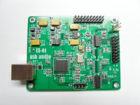
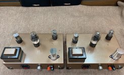
I recently built an 12AX7/KT88 prototype (I do not have "current" schematics for it, sorry), and I think it sounds good, but it is not very loud. I seem to be about to get around 100dB out of it on-axis from about only a foot away from some crappy desktop speakers. I'm also going for more hi-fi than a guitar amp, so I don't expect maximum gain(and I realize a negative feedback loop is missing, not relevant to the question however), but I'm still trying to figure out a few problems.

I looked up Uncle Doug's tutorial on how to measure power output from it using a 1kHz signal on an 8 ohm dummy load, and from my memory I was only getting a few watts (literally like 3W) out of it.

I'm powering it out of an old iPhone which I'm estimating only puts out about about 250mVrms.

Also my OT is a Hammond 1628SEA from Digikey (https://www.hammfg.com/electronics/transformers/audio/1627-1642.pdf). It's a 5k input impedance to multiple outs(I'm using 8), supposed to be rated for up to 30W.

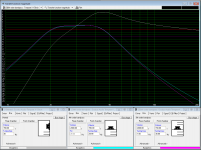
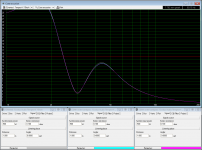
I understand different frequencies will have different responses, etc, but I wanted to try an exercise in LTspice to see if I could work backward, even if strictly theoretical and possibly unrealistic, and just pump in some raw numbers to see what I would get out.

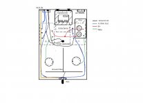
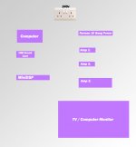
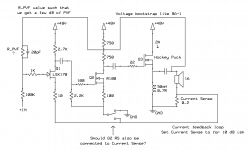
Here's my slop-matic:

RHWZQpE.png


There are many obviously unrealistic things about this schematic, but for the case of modeling, the idea was to swing the grid between -5V and -35V against a 530V B+, using a model(hopefully correct) of the OT matching the Hammond, into a dummy 8ohm load and see what I would get out. In this case, I was getting about 3.2Vrms across R10, which should translate to about 1.28W.

With the OT windings being 25:1 for 8ohm, my guess were that if I wanted to get this to 10x as much (12.8W), the secondary would have to swing 32Vrms, which means I'm at 800Vrms on the primary, which is more than B+ supplied even if I'm going after the opposite swing from the transformer.

I guess what I am trying to do is start a design again, working backward, and figuring out what I need to feed the OT, then what I need to feed the power stage, etc, etc.

I'm sure the things I'm doing wrong are almost innumerable, but if someone can point out a few big hitters, I can get my mind back on the right track.

Thank you!

Another AG9016 "addict"

Another AG9016 "addict"

Hi,

first of all my copliments on this forum, especially the links on tube related articles, often on entry-level, are very very helpfull.

As a brief introduction, I just finished (re)building my first EL84 SE amplifier (Kontakt KT7). Although I bought the amp in "working" order it needed some new capacitors and a by-pass of the input section in order to get a reasonable sound.

After a while I decided to fully strip the amp, and rebuild it from scratch with new (and preferably better) parts, and although I had minor knowledge on tube electronics, I managed to get it up and running again.

I am actually working on a site were the rebuilding process will be described in full with detailed pics, and as soon as it is finished I will drop a link as I feel that this could be interesting for other applicant Kontakt/Bocama/Lafayette rebuilders.

Now only recently I bought a philips AG9016 amp which is the next project I want to dig in to. I have read the topics on this forum on this amp, i.e. 40 yrs old philips AG9016 flea-power ?,
and there seems to be somesort of "improved" schematic were most of the C's and R's are removed?

There was actually an article in a magazine called A&T (!?!) how to "pimp" this specific amp, but somehow I cannot find it anywhere on the net.

To make a long story short, all (schematic) information, additional tweaks etc., are more then welcome !

Thanks in advance

Cees66

Which class D amps for portable sound system?

I'm trying to get amplification to drive a single passive 12" PA system, rated at 200 RMS, and an additional passive 12" subwoofer, rated at ~300 RMS. The amps will run off a buck converter connected to a 12v deep cycle battery. I'm looking for cheap, powerful, and energy efficient.

Right now I'm looking at buying two TPA3255-based amps:
AIYIMA TPA3255 Subwoofer Power Speaker Amplifier 300W Mono Hifi Home Audio Amplifier NE5532 OP AMP Bass Treble Adjust|Amplifier| - AliExpress ($45 each)
and run one in PBTL mode and one in SUB mode. It seems that the input power is limited to 35v, so I think this will give me ~120w RMS at 8ohm, for ~90$.

I'm wondering if there might be a cheaper, more powerful, or more energetically efficient solution. One idea I've been playing with is using a single TPA3255 with two output channels (2x300w), feeding in a mono main PA signal on the left input and the pre-filtered mono subwoofer signal as the right input. This would let me get away with using a single amp, for ~$50, also I'm imagining ~120-150 RMS at 8ohm, and possibly half the energy use. However, I'm not sure if this is feasible, in particular if feeding in main PA/subwoofer signals as left/right differential inputs is a good idea.

Any advice or thoughts would be appreciated.

FS: QA450 & QA401 Audio Analyzer

I'm upgrading to a (far more expensive) audio precision system.

Selling a lightly used Quant Asylum QA401 Audio Analyzer & QA450 4/8 ohm load.

Comes with accessories and cables to measure your DAC, amplifiers, speakers, etc. SNR, THD+N, crosstalk.. Lots of insights.

QA401 Audio Analyzer


– QuantAsylum

QA450 Programmable 8/4 Ohm Load [Retired]


– QuantAsylum


$500 + Shipping for both.

I would consider selling the QA450 separately.

High pitched noise IcePower500ASP + Nutube B1

I just finished building a Nutube B1 and a ICE Power 500ASP + 500A module. I noticed an increasing high pitched noise coming from the 500ASP though, the 500A seems fine and Im not sure what can it be. Im using star ground at power supply and connections seems as 500ASP user manual

An externally hosted image should be here but it was not working when we last tested it.


Any tips on where to start debugging?

Painting P-Audio PH-2380 Horn

Quick question; I'm thinking of doing a 15" build with the above horn, or something like it. I want to WAF it as hard as is practical, because whilst the new other half is quite prepared to let me build whatever I want, I don't want to look at an ugly speaker! How thick can you get away with painting the horn before it is detrimental to performance?

Cheers,

Russ

  • Locked
Please ban the racist term "Chi Fi".

Please ban the term "Chi Fi" from the forum. It is an example of cultural racism. I know that not all people, including forum management may be aware of modern forms of racism, so I will spell it out. Chi Fi is cultural racism because it's very usage implies that "Hi Fi" is the normal state, and "Chi Fi" is the non-normal state, and of course normal is therefore not Chinese. Research racism yourself if you do not accept this.

NAD 3020 noise simulated

As promised a while back, I simulated the NAD 3020's line stage. Total output noise comes out to ~3.7 µV A-wtd. Including the 23.7 dB power amp gain of this 25 wpc amplifier that brings this up to ~56 µV, this means a total (best-case) SNR of about 108 dB(A), slightly short of the claimed 110 but still very respectable for a little old amplifier.

With the (20k) volume pot turned down for a 2.83 V output, I'm getting ~111 µV(A), so about 88 dB re: 1 W / 8 ohms. Not too shabby at all.
Turned down further for 50 mW / 4 ohms, it's 68 µV(A), so about a 76 dB score on that.
There used to be amplifiers with even lower noise despite substantially higher output power, but those used a two-stage volume control (4-gang volume pots).

LTspice schematic attached.

Attachments

Cyrus PSX (original for Cyrus 2) Recap. - Which caps ?

Okay, so after this thread and warning shot..

https://www.diyaudio.com/forums/sol...-psx-blows-fuse-mains-plug-2.html#post6301599

time to replace the 4 x 15,000 uF 63 volts in the PSX.

Looks a simple job, just 4 caps to desolder and resolder.

So which replacement caps are suitable based on uF, voltage and sizing.

I just quickly Googled, 15,000 uF, 63 volts - I think that's what they are...

and found these on Mouser...

LKG1J153MKNF Nichicon | Mouser United Kingdom

Are these any good ?

and recommendations ?

Speaker and amp for diy Smart assistant

I just got the edict from my wife that Alexa is creeping her out, and that I need to find a different solution. I also got permission to spend money!😀


I'm looking to setup a locally hosted smart home assistant, and wanted some recommendations on small (<=3"), inexpensive (<$15) speakers of reasonable volume, and that are clear enough for the synthesized voice. It would also be nice if the overall depth was somewhat shallow.


I've used the FE85 in the past (currently listening to them now actually), but they need a (relatively) big, sealed, enclosure to sound good. I plan to 3d print the enclosure, but I don't think I can get away with sealed since I'm gonna put a rpi and microphone array inside. Some of the neodynium speakers from Dayton Audio seem like a good match, but I'm not sure if they are any good.


For the amp I plan to use this TDA2822M based amp from parts express: TDA2822M Low Voltage Stereo 2 x 1W Audio Amplifier Board (although I may not actually need the analog volume control if I can do that digitally). I know its <$5, and I will not be using this for playing music; are there any fatal flaws that would prevent me from using this amp?


Thanks all!

Help with Crossover for MW144 TL

:cop: Split from http://www.diyaudio.com/forums/multi-way/68301-my-morel-mtm-project-6.html#post4796981

I have a mw144 with 30s in a transmission line. The cab is near enough the ipl M3
link: IPL M3TL mk3 Transmission Line

I think it's 8 years since I first posted, looking for help. I think I had probably been at it 8 years then. On and off.

They are OK, with a 2nd order about 2.8khz. It's nothing special though and I have taken many db away from the 30s to improve things. Leaving the tops about as loud as the bass, but a hump between 500hz and 1khz making them sing more than dance. I like dance.

Time change and so have my hobbies. It's electric bikes now. I would like to try some different crossovers though. Just not design them. Are there any designs about that are polished enough to copy with reasonable success?

driving control input with led output on Icepower

I am combining a 700AS2 and a 200AS2 in the same chassis. I want to use the the 700AS2`s 12v trigger function to bring it out of standby. The problem is that the 200AS2 is normally on, and can only be put in standby with a 5v signal.

Would it be possible to connect the standby led output from the 700AS2 to the standby input on the 200AS2? It requires 2.8V on a 20kohm load to trigger.

I have attached the datasheets for both.

Attachments

headphone cable repair

I have an earphone that I often use while working. The single driver allows me to listen to music yet still hear and converse with coworkers and customers. Somehow the outer jacket of the cable got abraded, exposing the inner wires and the ground shield.
I lucked out and found that dipping the worn section into a can of "As Seen on TV" Flex Seal and hanging it to dry is the most perfect repair that a person could hope for.

help with replace upgrade or replace amp boards

Realised I posted this query in the wrong place.

Title should be repair, upgrade or replace amp boards.


The darlingtons (mj11015/6)on my Virtuoso power amp have failed and I'm considering replacing the amp boards for something more modern and better than the Virtuoso. It's an old design by Graham Nalty in ETI with loads of esoteric components, holco h8 and h2 resistors, Mat02 (ssm2201) transistor pairs, wonder caps. I've added schottky diodes, silver wire and kimber cable etc.

The power rails are +-56v dc with a separate regulated supply for the low power gain stages.

To put it into context, it's current build it is better than a rotel rb-991(more air and detail) and recently caused a friend to upgrade his Naim 140s. I haven't had the chance to compare it with anything else recently. My friend was supposed to bring his naim 250? over but covid got in the way....plus I blew my amp up :blush: :headbash:

Alternatively I could consider alternative better darlingtons or mosfets (the amp was also designed to allow mosfets RFM10N15/P15 to be used with the removal of some parts and adding gate resistors.)
I was looking at faster darlingtons or the exicon mosfets but to tell the truth I have little idea on what other changes to ensure that they will work.

It also needs to be able to drive my Martin Logan Sequel IIs and handle all genres of music from classical, folk, blues to rock as I listen to all good music irrespective of "designation"!

Pre-amp is Versatile LDR designed by Rudi_Ratio who kindly posted his design and organised a group buy on this forum. Sounds Great!! Thanks also to George who did the groundwork for LDR preamps.


Any advice or suggestions appreciated.

Attachments

PSUD2 warning: IFRM exceeded

I am using PSUD2 to design a PSU using 5AR4 rectifier.

I think I used too much capacitance, but it can't be helped. During the first second it throws a warning about the IFRM of the rectifier is exceeded.

I'd imagine the rectifier tube isn't warmed up yet at that point and shouldn't be conducting much. Do I need to pay attention to the warning?

Or do I need an inrush current limiter?

Combining a 2" exit driver with a HF unit as a point source. Is it possible?

During the last days, I was reading a lot of posts about paraline, combining compression drivers, directional arrays, Unity/Synergy horns and so on.

I wonder if there is a way to integrate for example JBL2445 or similar driver that is lacking in the HF with some sort of device to have point source behavior at a relatively short distance - say 1.5 m and further. If possible, it would be nice not to use digital delay between the two units, but can be used if necessary. I would like to crossover the JBL2445 at around 600 Hz

The best I have tested so far was to use two identical horns for the JBL2445 and HF compression driver with an adapter to match the time of flight to the listening position and to integrate well at least in the horizontal plane. This is as good as I can do. Would it be worth trying to pursue alternative ways?

The tools available include a 3D printer and DSP for delays, crossover and EQ.

I see some potential ways to try out.

1) use two paralines to combine the 2" and HF drivers into a conical horn. One shorter, one longer, maybe trying to steer the wavefronts a bit towards each other. The path lengths could be matched by using phase plugs going into the throat of the 2445 and HF driver to keep the conical expansion as close to the throat as possible, the HF driver would include an adapter for the correct distance.

2) use one paraline with both drivers - matching the pathlengths mechanically should be possible as well.

3) Use Danley throat combiner-like device to use both in one horn. Or any other similar device to make the drivers combine into one horn. The HF driver can be again made to have a 2" exit and same distance from membrane to throat as the 2445

4) "Inverted" Unity - to have the 2" driver in the center and multiple HF feeding into the horn. Most probably a very bad idea.

5) Place a small HF with horn inside the MF horn hidden in a phase plug like device and use delay to match the path lenghts.

6) Similar to 3, but Unity style - the 2445 would be fed to the horn through the side of the HF throat adapter at the correct place.

7) Anything else? Including that to have two identical horns is as good as it can get? And that a conventional unity is better in this regard...I would really like to use the 2445s.

All of above should be possible to at least prototype with a 3D printer, so any guidelines would be appreciated - e.g. rule out the really bad ideas. The 2445 can be equalized up to some 8 kHz without sounding too bad. The desired coverage pattern would be 90Hx60V or smaller, as low as possible. In this case, space occupied by the horn(s) is not a concern.

Input LTP bjt replacement

Working on some “450w” kits. I figured the rating was for 4 ohms, with the OP and drivers rated at 230vce, I stuck it into a +/-90vdc psu. Tested and got about 350w/8e and 550w/4e at clipping. The kit survived, one of them is in service running the mid woofers in my HT system for a couple of years now. As I look around to make a few mods in another one of these, I notice the input stage comprises mainly of 2sa970 and 2sc2240’s. If memory serves these are 120vce devices.... and they are subject to the full 90vdc on their emitters. I am wondering if I should change them out for something in the higher voltage range or leave them in there.

Any suggestions?

Testing new build with a multimeter, weird measurements

I just finished building an amplifier with a preamp inside. Im splitting the AC input into the amplifier (directly) and the preamp + input selector, through an AC/DC converter.ñ, the input selector has a buck converter to go down to 5v (from 24v) Everything with star ground at main.

What I find weird is that if I touch with the black line the + of the preamp (24v) and the + of the input selector (5v), it shows continuity. The same if I touch every other point (except for the AC wired). Is this expected?

Speaker kits for Croft Series 7

Hi all

I've just acquired a Croft Series 7 power amp to drive my RX5 speakers. Preamp is also Croft.

It sounds pretty good but I sort of thnk the RX5 isn't the bestmatch - fun but occasionally closed in a bit

I'd be grateful for suggestions of speaker kits which may go well - IPL acoustics trasnmission lines or perhaps Wilsmlow Audio or anythig else recomended.

Time short for doing my own cabinets from scratch!

Thanks all
Listen to almost anything but lots of choral and organ music.

Buffer capacitor on class D design

I bought an ICE Power 500ASP + 500A module and while reading the design manual, I noticed they use a buffer capcitor of 10000uF/150V for (star) ground and Im wondering, what’s the reason for this?

https://www.parts-express.com/pedocs/manuals/icepower-asp-series-manual.pdf page 44

They also mention this at page 12
“Adding an optional capacitor on the main DC-bus will significantly increase t150 as evidenced by the numbers given. This can be exploited in subwoofer applications, where it results in improved ability to handle transients”
But cant figure out what does it means

CS4272 stuck in power down mode

Hello,
It's about an audio codec ADC/DAC CS4272 https://statics.cirrus.com/pubs/proDatasheet/CS4272_F1.pdf I'm trying to put it to work with this USB to I2S module XMOS Multichannel high-quality USB to/from I2S/DSD SPDIF PCB - DIYINHK Schematics are attached, as well as the DIYINHK module requirements. Connections seem quite straightforward. I'm assuming that BCK is the same as SCLK, correct?

The DIYINHK module gets recognized by the PC and the drivers are loaded. But I don't get any sign from CS4272. Even Vref and Vcom stay at 0V. Vcc and Vdd are OK. To my understanding this means power down mode, doesn't it? I tried two chips I had available and both do the same thing. There is some info on CS4272 datasheet page #35 about ADO/CS (pin #13) but my lack of knowledge doesn't help me with this... In my case (copied design) ADO/CS is attached to ground. Do you think this could be the reason?

I realize that remote debugging is too much to ask so, I would appreciate if you could at least verify Cs4272 and DIYINHK module campatibility.

Attachments

  • Xmos.JPG
    Xmos.JPG
    154.7 KB · Views: 407
  • AudioCodec.JPG
    AudioCodec.JPG
    61.8 KB · Views: 835
  • I2S.JPG
    I2S.JPG
    68.5 KB · Views: 380

Cambridge R50 project

Hi all! I'm new to this site, but during lockdown I have re-kindled my love of HiFi.

Back in 1975 (I was 17) I purchased a pair of KEF Kit 3's and filled my bedroom with 2 large home made cabinets. Marriage and kids came along and we could no longer accommodate the 'beasts'. I kept the drive units and crossovers and the boxes went!!!

45 years later the drive units were dusted off and tested (one B110) dead, the rest fine and the crossovers re-capped.

By chance, a pair of R50 cabinets appeared on the web and transported back to our home France. 2 Manocor AD 135's (to replace the B11's) purchased and everything soldered and screwed together. In total these speakers have cost me less than £150.00 and they blow my socks off! A lovely 'open' soundstage and soft rich bass. I'm hooked!

Circlotron amp using N-channel mosfets

Hi friends. This my very first post.

First off, I decided to name myself after what I think is the most fascinating amplifier topology I have ever seen - the circlotron. It is a model of simplicity and symmetry. I particularly like it because after drawing the basic circuit about 50 different ways to try and make it look the most logical, I noticed that if you place 2 loudspeaker loads on it, 1 between the sources and the other between the drains, it can be drawn as a perfect tetrahedron! As far as I was concerned that was the icing on the cake for a most aesthetically pleasing ampifier.

Now that I have firmly established my reputation as a nutcase, uh, sorry, *enthusiast*, Let me talk amplifiers. I discovered this circuit only a few months ago, and as it turns out I have quite a few large collection of hexfet switching type mosfets laying around at home. The last mosfet type amp I built was the Electronics Today one, back in about March '81 I think. It used complementary fets and I never felt comfortable with P-channel devices. They always seemed the poor cousin (or brother/sister?) to the N-channel. Then I found the circlotron cct that would let me use both N-channel devices. Coolarama! I wound up a driver transformer, picked a matched pair and away it went.

I started a thread on Google Groups that I will part copy and paste to here, telling of my adventures with this cct if anyone is interested. One unusual thing I did was to use a ferrite core tranny normally used in a switchmode supply for the driver tranny. With sufficient turns on the core it works really well, contrary to the advice I was given by others.

Anyway, I think the topology is the greatest thing since sliced bread. I hope there are others out there that are perceptive enough ;-) to also see what is so great about this cct.

Regards. GP.

Can anyone help me with this tweeter removal? Focal Chorus 836V

Hi there!

I'm having some trouble and thought this might be the best place the check. I've left VMs and emails for anybody that might be in the know but haven't heard anything back.

I have the Focal Chorus 836V

https://www.focal.com/sites/www.foc...rus-800-v-enceintes-colonnes-chorus-836-v.jpg

with:

http://www.easylounge.com/Content/photos/f/o/foctweeter-tnc,33223-1200px.jpg

I got these speakers recently from a family member that drove them with a Emotiva amplifier without issue. As soon as I plugged them into my Onkyo 805 it blew the crossovers and the the tweeter/midrange on the one side. I assumed it was only the crossovers so I had them redone but of course the drivers are still not working despite having all the blown up parts in the crossovers replaced. I have a centre channel with the same mid and tweeter that I'm not using so I'm trying to use the components from that. The mid is easy enough but how do you remove this tweeter that seems to be glued on? Frustrating!

General question for Ground zero GZPA 1.4k,1.8k a.s.o.

Hello, the last time i had a few difficultys with this type of amps.

Repaired the outputs... On some amps, it was also neccesary to change the irs 21844s.. Checked everything, complete new batch of mosfets. All parts from mouser. Tested the gate-source with a cap, everything looks fine. Final check of the amps also ok.. Customer happy, everything works, even under full load for a longer time... After a few days, or a week, the amp goes in protect, with small load, or only on, with no music playing..


Found two output mosfest short, one highside, one low side from the same bank. Couldnt find anything wrong...


Is there something, what i dont see, maybe somebody can give me a hint, where or what to look...
Projects by fanatics, for fanatics
Get answers and advice for everyone wanting to learn the art of audio.
Join the Community
507,811
Members
7,889,464
Messages

Filter

Forum Statistics

Threads
406,298
Messages
7,889,464
Members
507,811
Latest member
Cystore