You are using an out of date browser. It may not display this or other websites correctly.
You should upgrade or use an alternative browser.
You should upgrade or use an alternative browser.
Filters
Show only:
[WTB] Help purchase pair of tweeters from Avito [Russia]
- By electronic
- Swap Meet
- 0 Replies
Kindly request some assistance in purchasing a pair of tweeters from Avito and have them delivered within the EU.
Will pay for the time spent.
Will pay for the time spent.
4-way FIR crossover thoughts...
Halo!
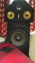
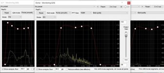
So yeah, my 4-way active monitor speakers are ready to launch, but I have some questions regarding proper tune of FIR crossover.
My project is aimed to provide studio-quality transparent and analityc sound like a hi-graded studio monitors. I gonna work on mixing and mastering, so any hi-fi colorings are not interested for me.
My questions:
1) Is there any sense to use such a crazy 90 db/oct filter slope, or "just 60 db/oct" will be enough? (There is enough nominal power in speakers and amplifiers, and they're located as close as possible.)
2) Reasonable FFT size? 16k, 8k, 4k?
I'm attaching some photos of my system and screen of current settings I was using for 3-way (Until subs arrived).
Attachments
miniDigi replacement?
Can the Digi-FP be used to interface to MiniDsp 2x4?
Since the demise of the MiniDigi I want to use the MiniDps2x4 for an all digital Ambiosonic solution (which only runs on the 2x4).
Since the demise of the MiniDigi I want to use the MiniDps2x4 for an all digital Ambiosonic solution (which only runs on the 2x4).
How to LR 24db active crossover
- By Mindsource
- Multi-Way
- 33 Replies
Can anyone point me to a thread that explains how to implement a LR 24db active crossover? I'm sure there must be one somewhere but my searches have come up empty. I don't know where to set the corner frequencies. I'm using Sigma Studio fwiw.
Thanks,
Shawn
Thanks,
Shawn
Difference about source resistors on Quasi design
- By Dbnn
- Solid State
- 1 Replies
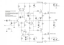
Hello world, i'm design on my own pcb the popular quasi nmos350.
i'm confused about source 5watt resistors, i have seen modules with the resistor on vcc- side on drain and modules with source resistor on source
whats the difference?
In quasi designs i know we must connect the source (emitter on BJTs) with resistor to keep the difference on transistors / fets to minimum condition.
in my case the connection output-resistor-drain on down (vcc-) side is helpful.
Attachments
BA-3 Preamp - Hummin' & Buzzin'
- By matchstick20
- Solid State
- 2 Replies
Hi all,
I just finished building my BA-3 Preamp, biased it up properly, and have thrown it into my system (active dynaudio's for the moment) ... and it sounds wonderful! Crazy soundstage and clarity - can't thank you all enough for your shared knowledge (especially 6L6 for his build guide).
However...
I am having some issues with buzzing and hissing in both speakers. It's not apparent at low to medium volumes, and I'm able to use it as is, but I plan on building an F4 paired with some high efficiency Klipsch's so it'll definitely be an issue down the road.
The hissing is always present and the buzzing (120hz) increases when i turn the volume pot up. When inputs have load, it's only noticeable when I get really close to the speakers - when there's nothing connected to the input, its VERY LOUD!
My first test was to check if its being pushed too hard and has too much gain: my results from a sine 1k test.
-In: 0.847vac
-Out: 6.22vac
I don't believe that is too far out of the range of what its supposed to be, correct?
Next, on the advice of another member, I removed the PSU from one channel to check for ground loop, hum and buzz remained
Lastly, I plugged the preamp into a ground remover plug and turned on very briefly, problem persists.
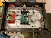
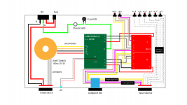
I'm still leaning to think it is a ground loop problem, but i'm quite novice so it may in fact be something else entirely. I've attached a build photo along with a graphical layout of my build.
I'm certain you all know more than I do here so any help would be greatly appreciated 🙂
I just finished building my BA-3 Preamp, biased it up properly, and have thrown it into my system (active dynaudio's for the moment) ... and it sounds wonderful! Crazy soundstage and clarity - can't thank you all enough for your shared knowledge (especially 6L6 for his build guide).
However...
I am having some issues with buzzing and hissing in both speakers. It's not apparent at low to medium volumes, and I'm able to use it as is, but I plan on building an F4 paired with some high efficiency Klipsch's so it'll definitely be an issue down the road.
The hissing is always present and the buzzing (120hz) increases when i turn the volume pot up. When inputs have load, it's only noticeable when I get really close to the speakers - when there's nothing connected to the input, its VERY LOUD!
My first test was to check if its being pushed too hard and has too much gain: my results from a sine 1k test.
-In: 0.847vac
-Out: 6.22vac
I don't believe that is too far out of the range of what its supposed to be, correct?
Next, on the advice of another member, I removed the PSU from one channel to check for ground loop, hum and buzz remained
Lastly, I plugged the preamp into a ground remover plug and turned on very briefly, problem persists.
I'm still leaning to think it is a ground loop problem, but i'm quite novice so it may in fact be something else entirely. I've attached a build photo along with a graphical layout of my build.
I'm certain you all know more than I do here so any help would be greatly appreciated 🙂
Attachments
Nikko Alpha 230 User and Service Manual
- By wild-gazer
- Solid State
- 1 Replies
Hi all, I am new to the site so please forgive me if I am posting this question in the wrong place. I recently (yesterday) purchased a Nikko Apha 230 and am looking for a copy of the user manual as well as a service manual (want to learn more about the amplifiers design). I've not had a chance to power up the unit yet but was told that it works fine but just in case it'd be great to have schematics for it. Much appreciate any assistance you could offer.
Howard.
Howard.
WinISD midbass graphs - building a soundsystem
- By ubersafka
- PA Systems
- 41 Replies
Edit: Im going with 2 x Fane Colossus 18XB, 2 x Fane Sovereign 12-300, 2 x BMS 4554 1.4" compression drivers & Crown XLS 5000, t.amp TSA 4-700 & Behringer DCX2496
I have been wanting to build a soundsystem for a while, and as my school where I study as a carpenter ends in 3 months, now would be my best time to do it. I can get the plywood for -30% of the price through school.
I didnt really know anything about soundsystems before couple months ago, and I have never made a speaker before, but after vigorous hours of googling through the last 4 weeks and with some help from a few friends with soundsystems I think I have been able to make an okay plan
The budget (discluding plywood/amplifier) was around 1200€ without much room to go over it. It will be a single tower so that the transportation would be manageable with backseats+trunk of a normal car and not having to need a van. It will have 2 subs for under 100hz, 2 mids and a high top (unless I need 2?). I would mostly play electronic music focusing on lower frequencies.
I have decided on using 2 x Fane Colossus 18XB-8's as subwoofers;
https://www.fane-international.com/view-product/colossus-18xb#tab-1
In a cabinet design like this;

this way it will be a single tower, without being too high for the high top and so that I could pile it up without a ******* ladder
As for the midbass I havent made up my mind yet as I only started using winISD today, but I thought about using 2 x Fane Sovereign Pro 12-500's;
https://www.fane-international.com/view-product/sovereign-pro-12-500#tab-1
The cabinet would be a basic vented enclosure, but I havent really been able to find other graphs for midbass to compare mine with, so Im not sure if I've completely screwed some value in my WinISD. here are two graps for a 50 and a 65 liter cabinets for the mid Fane Sovereign Pro 12-500
50 liter;

65 liter;

I havent found other midbass graps to compare these with, do these waves look okay? is the high wave at the start due to the fane 12-500's xmax of 6, or should there be no wave. Or have I completely ****** a parameter and this looks nothing like it should
I'm using drivers available in my country, I don't want to order 80kg from abroad. Many of the "approved" drivers I found were not available anymore, or were better suited for scoops. I havent read much about high tops yet, I was looking at Monacor MHD-152 though;
https://www.monacor.com/en-us/monac...hnology/pa-tweeters-and-horn-drivers/mhd-152/
I have been wanting to build a soundsystem for a while, and as my school where I study as a carpenter ends in 3 months, now would be my best time to do it. I can get the plywood for -30% of the price through school.
I didnt really know anything about soundsystems before couple months ago, and I have never made a speaker before, but after vigorous hours of googling through the last 4 weeks and with some help from a few friends with soundsystems I think I have been able to make an okay plan
The budget (discluding plywood/amplifier) was around 1200€ without much room to go over it. It will be a single tower so that the transportation would be manageable with backseats+trunk of a normal car and not having to need a van. It will have 2 subs for under 100hz, 2 mids and a high top (unless I need 2?). I would mostly play electronic music focusing on lower frequencies.
I have decided on using 2 x Fane Colossus 18XB-8's as subwoofers;
https://www.fane-international.com/view-product/colossus-18xb#tab-1
In a cabinet design like this;
this way it will be a single tower, without being too high for the high top and so that I could pile it up without a ******* ladder
As for the midbass I havent made up my mind yet as I only started using winISD today, but I thought about using 2 x Fane Sovereign Pro 12-500's;
https://www.fane-international.com/view-product/sovereign-pro-12-500#tab-1
The cabinet would be a basic vented enclosure, but I havent really been able to find other graphs for midbass to compare mine with, so Im not sure if I've completely screwed some value in my WinISD. here are two graps for a 50 and a 65 liter cabinets for the mid Fane Sovereign Pro 12-500
50 liter;
65 liter;
I havent found other midbass graps to compare these with, do these waves look okay? is the high wave at the start due to the fane 12-500's xmax of 6, or should there be no wave. Or have I completely ****** a parameter and this looks nothing like it should
I'm using drivers available in my country, I don't want to order 80kg from abroad. Many of the "approved" drivers I found were not available anymore, or were better suited for scoops. I havent read much about high tops yet, I was looking at Monacor MHD-152 though;
https://www.monacor.com/en-us/monac...hnology/pa-tweeters-and-horn-drivers/mhd-152/
Attenuation resistor
In case I want to attenuate tweeter and midrange with the same rate with resistors placed in series on the amp side or before passive crossover network, Can I combine the tweeter and midrange paths together to use only a single resistor?
One tube brighter/hotter than the others
- By Sabicas
- Tubes / Valves
- 38 Replies
I just fired up an old Magnavox tube stereo console (late 50's, early 60's?) and everything was fine at first. Then, I noticed the right speaker wasn't working, it was barely audible with distortion. When I power the unit off, the right channel is suddenly became clear and strong for an instant just before shutdown. If I let it sit for awhile before powering on the console, the right channel works for about 30 seconds and the same results that I described above occur.
So, I pulled off the rear panel and noticed that one tube was glowing brighter than the others on the power amp. There's a section with four tubes in a row (6BQ5) and the third one was glowing hotter. So, I powered it down for a while and swapped the third tube for the second. When I powered it back on, the same thing occurred, the different tube in the third slot was glowing brighter and the audio cut out again. I know that it's a bad idea, but I lightly touched the tubes and that third tube is super hot compared to the others.
I'm posting the schematic that was inside the rear cover and another photo to demonstrate just how much brighter that one tube is than the others.
What do I do now? Any help would be appreciated.
Attachments

Service manual wanted for Yamaha RX-v385
- Solid State
- 4 Replies
Looking to fix one that won't power up.
BMR speakers
- By Stallion63
- Full Range
- 19 Replies
Hi all! Has anyone here tried using the Tectonic full range BMR speakers? I know they're cheap.Just asking for opinion.
I bought a pair of the 3-1/2" TEBM65C20F-8 a couple of years ago and briefly tested them before putting them in storage.
Connecting them directly to my 2 way tower speakers' binding posts without any crossovers,they seemed rather good with male voices but I don't think they can go up to the 20Khz they are rated at. Any thoughts on them?
GB TL783 negative LD1085 heater supply boards.
- By v4lve lover
- Group Buys
- 10 Replies
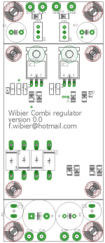
Ive designed boards for a little module that is supposed to provide regulated bias and regulated 6.3/12.6VDC at up to 3A continuous. for use in tube amplifiers.
The regulated bias is with a TL783 that will accept up to 125VDC in. and should provide -40 to -80V adjustment range on the bias supply.
The LD1085 supply is SB560 skotkey rectified, and should be able to produce 6.3VDC from 7VAC using a 6800uF cap
The board has a substantial heatsink of 2.3K/W because i stocked up on those. dimensions are 78x50x40mm.
Mechanically the board is about 120x50mm with M4 mounting holes from the side. The cooler mounts on the back, so do the capacitors, at the top and bottom of the board. The parts on top of the board are low profile, so the board can be mounted with the SMD parts down.
Suggested price for the boards alone is €2,50. The cooler including mounting hardware is €5 And a complete kit with the SMD parts soldered should cost around €25 excluding postage.
The board can be used to mark out the six m3 holes that need to be tapped into the heatsink.
Any interest?
Attachments


Hammond 'standard' OPT vs the 'A' version
- By prairieboy
- Tubes / Valves
- 18 Replies
I'm curious if there is a measurable/audible difference besides the 'easy wire secondary' in the A series OPTs? Anyone with any experience or opinions (on this subject)?
Car Audio Room Curve
- By bradleypnw
- Car Audio
- 8 Replies
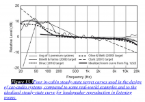
Do you guys equalize your car audio systems to match an idealized frequency response graph?
Do you adjust it for driving speed and resulting road noise?
I saw this graph and wondered how car audio DIYers approach equalization in practical terms.
Do you adjust it for driving speed and resulting road noise?
I saw this graph and wondered how car audio DIYers approach equalization in practical terms.
Attachments
Is Vbe reliable indicator of junction temperature?
- By chip_mk
- Solid State
- 26 Replies
Usually we calculate junction temperature from collector dissipation (easy to measure) and Rth from datasheets. Once we have working prototype we can measure case temperature and infer the junction temperature.
Can we instead calculate Tj from difference in Vbe measured immediately after a cold start (when Tj is supposedly equal to the ambient temperature) and again when the thermal equilibrium is achieved?
This is the formula:
Tj = Tamb + (Vbe1 – Vbe2) / tc
Tj - operating junction temperature
Tamb – ambient temperature
Vbe1 – base emitter voltage measured immediately after a cold start
Vbe2 – base emitter voltage when operating temperature is reached
tc – temperature coefficient, ~ 2mV/C for silicon BJT
I suppose measuring the Vbe1 is the most challenging part. Allowed time to make the first measurement depends on the physical size of the device. For small devices thermal time constant might be too low for reliable measurement with common multimeter.
BTW the same method could be considered also for MOSFET devices.
Your comments are welcome.
Inductor question
- By pop4richard
- Multi-Way
- 8 Replies
Hi
I have a crossover to repair that requries a 3.3mH inductor. Can I put a 3.0mH plus a 0.3mH in series to make the 3.3mH total?
If yes, do they need to be arranged in any specific orientation to each other?
Can I mix an iron core and air core together?
Thanks.
I have a crossover to repair that requries a 3.3mH inductor. Can I put a 3.0mH plus a 0.3mH in series to make the 3.3mH total?
If yes, do they need to be arranged in any specific orientation to each other?
Can I mix an iron core and air core together?
Thanks.
Micro-Cap Tubes Parameters question
- By Joshua_G
- Tubes / Valves
- 23 Replies
I have Micro-Cap 9. It has a 6DJ8 tube in it. I'd like to change the parameters to a different tube, which isn't in it's database (6H30).
Those are the parameters for 6DJ8:
+PARAMS: LIP= 1.5 LIF= 10 RAF= 0.09 RAS= 0.2 CDO= 0
+ RAP= 0 ERP= 1.35
+ MU0= 33 MUR= 0.02 EMC= 0.0000795
+ GCO=-0.2 GCF= 0
+ CGA=1.40E-12 CGK=3.30E-12 CAK=1.80E-12
Out of those, I get what MU0, CGA, CGK and CAK are.
I have no clue what the other parameters mean.
Does anyone here know?
Earthquake PHD2 seems to lower output???
I have a PHD2 I bought new from a guy around a year ago. It was great and had way more power than I needed. One day at work the guys and I were bored and we wanted to smoke a speaker for fun. (yeah, I know STUPID ME) Anyways, we screwed this 6" woofer to my back deck, just to see how much bass it would produce before we smoked it. Well, as soon as the speaker burned, the coil must have shorted to the frame and then to ground through the back dash. The amp shut the entire car down it was drawing so much current. I had to go under the hood and disconnect its main fuse.
After sending it to Earthquake in Cali., and spending much dinero to repair it (I had attempted to repair it by replacing every power supply and output transistor with the original part numbers but it still wouldn't come on) I got it back almost two months later. They somehow kept forgetting to send it back to me. Now when I turn the volume up high enough to pound the 12" mtx 7500's it seems to automatically turn the volume down a little even though the car's voltage isn't dropping much and the subs are aok. It never did this before I fried it on the cheezy 6" woofer. The only thing I noticed different on the amp board is a diode soldered across two of the legs of the power supply pwm IC, or at least that's what it looks like. Of course the IC has the part number ground off so I couldn't change it when I attempted to repair it myself. (that was the only part they changed, besides replacing the ones I changed with the SAME part number transistors🙄 )
-Does anyone know why they soldered that diode across the top of the pwm ic? Is it some sort of power limiter to protect the amp from me running too low of a load?
-If so, can I just remove it? I never run lower than 2 ohms nominal load, I just made the mistake of having the amp ground to the car's body ground one time. I tried getting ahold of the techs at earthquake to ask about the IC and the diode but couldn't.
-The amp never did this before they repaired it and I want it back to normal. I told them about it and they said "It tested aok and made full power" I was like, yeah, whatever. Thanks🙄
-
Poll
Dynaco ST-70 Series III
- By dmfraser66
- Tubes / Valves
- 58 Replies
A new company with a strong reputation in professional music has acquired the Hafler and Dynaco brands and intellectual property. I will not say who as that may be considered advertising.
Our question is:
For an ST-70 amplifier would the preference be for:
1. An amplifier as faithful to the original ST-70 but incorporating the improvements of that have been done to it by the audio community but using no New Old Stock parts. Sorry, no 7199 input. But following the original Pentode-Triode input circuit with feedback.
2. The best possible amplifier that will still use the EL34 output but where the input/driver uses new topologies for what we feel will be better sound quality. We have spoken with people who knew David Hafler and we would basically do what he would have done today if he were around. However, the signal path will still be through tubes.
Either of these made with all new parts will have an MSRP a little north of US$1200
We ask because there are so many old and rebuilt ST-70 amplifiers out there, that some here have felt that a person who wants the original 1950s sound quality will just buy one of the original or reproductions for a lower price. That a person buying a new unit wants something that is competitive with a current well rated tube amplifier.
Note that the lead engineer on this project received their basic electronics education in the 1960s on tubes and has been involved with the audiophile community for decades. This is not just some rebadging exercise.
Regardless, as a long time DIYer, I would appreciate the input of the DIY community on the approach to take. And your comments do not need to be limited to the ones I have given. For your suggestions, all I ask is that you only recommend tubes that are still in production.
Good looking horrible sounding bookshelf for 100EUR
- Multi-Way
- 13 Replies
Since the arrival of Corona Ive been bored and since planning my next DIY project for summer vacation, but due to uncertain financial future I scrapped my original plans for something cheaper: a small bookshelf based on some simple car-audio kits. It was fun to assemble this simple design and now I have something for the winter fireplace (as expected it sounds horrible). All jokes aside I will probably buy better drivers as I'm very happy with the wood work and definitely learned a lot in the process as preparation for next bigger projects.
Size outer: 30*20*18 cm
Cost:
Wood: 2pc of 300x2100x18mm pine = aprox 40 eur
Car audio kit 6,5" Biltema: aprox 55 eur
Glue and paint I had from before.


Size outer: 30*20*18 cm
Cost:
Wood: 2pc of 300x2100x18mm pine = aprox 40 eur
Car audio kit 6,5" Biltema: aprox 55 eur
Glue and paint I had from before.
An externally hosted image should be here but it was not working when we last tested it.
WTB: Yamaha JA3882 woofer
Looking for JA3882, original, in good condition. Need one woofer.
thanks,
Herman
thanks,
Herman
How to take low level signal from an OPT ?
- By academia50
- Tubes / Valves
- 66 Replies
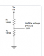
I need to take an audio signal from the output of the terminals of a valve amplifier, to send to the input of a Bheringher power amplifier.
I currently have that configuration (I have no other possibility) with a DaytonSPA250 board amplifier that has high and low level inputs. But I don't have the circuit of it.
I know that it is feasible then, (I understand that I should build a resistive voltage divider) but I have my doubts if it applies exactly the same to a valve amplifier or there would be some specific inconvenience.
Could someone guide me about it? Any link? Thanks in advance !
Repairing MARANTZ PMD420 cassette recorder
- By epowell
- Analogue Source
- 37 Replies
HI Folks
I'm new here... if anyone would like to check out who I am - please visit my site Edward Powell - I'm a musician and instrument maker
I have an excellent old MARANTZ cassette recorder that needs some work in order to get it functioning properly --- I love cassettes and that's all I listen to in my 1981 VW bus...
Please if anyone has some experience with this I really could use some help - THANKS
Edward
Krohn-Hite UF-101's?
- By V FETish
- Tubes / Valves
- 4 Replies
So I got a pair of these last week and I'm wondering what to expect from them. Anyone have these? Comments would be highly appreciated since I won't be running them until the late fall due to the extra heat they make.
These have fantastic specs but I was told elsewhere they achieve those by using lots of feedback and some other tricks that make them sound bland. They came with a pair of QUAD ESL-57's which I was hoping would be a match made in heaven.
These have fantastic specs but I was told elsewhere they achieve those by using lots of feedback and some other tricks that make them sound bland. They came with a pair of QUAD ESL-57's which I was hoping would be a match made in heaven.
Subwoofer in closed cabinet
- By bansuri
- Subwoofers
- 15 Replies
I wrote this white paper to encourage people to build a subwoofer in a closed box.
Attachments
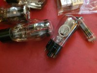
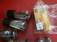
Fos sale tube package Nos,used and new
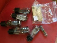
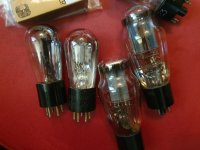
For sale whole package of tubes that I never use and I dont need this anymore.
2 x Sy227 Sylvania mesh plate matched pair mesured 1000 and 1050 ,buyed from tube depot Usa
2 x 6h30pi Electroharmonix matched pair New buyed by Hifi Collective UK
2 x 5u3s Russian rectifier grey plate Nos
1 x Az 11 Valvo mesh plate,glued base,Nos
1 x Ez81 Rft Germany rectifier Nos
For all tubes the price is 120euro plus shipping 8,90 euro inside EU,excludit UK.For all other countrys pkese ask for shipping cost.Payment thru paypal.For info or offer plese contact me.
Attachments
ICE Power 50ASX2
I'm working on a faulty Gallien-Krueger '200Watt' bass amp that has an ICEPower 50ASX2 modular amp fitted.
PSU +- 25V Supplies OK, No audio output due to pin 1 (enable) of connector P102 being LOW and disabling amplifier, (should be +5V when NO connection to it). Nothing appears physically damaged on the board. (Pins 2 & 3 protection outputs of P102 are OK at +5V). Looks like it is fed from IC400.
Very occasionally when switching off the audio input signal will 'burst through' briefly, so I dont think its a 'big problem'.....
Anyone encountered this ...or solved it?!
THANKS
Tannoy Sandringham crossover
Hi everyone, this is my first time here.
I wish to ask if somebody has the Tannoy Sandringham crossover schema.
I'm trying to do them by myself starting from Tannoy 2062 loudspeakers, but I didn't really find any information about crossover.
Thank you in advance for any help about this, really appreciated!
I wish to ask if somebody has the Tannoy Sandringham crossover schema.
I'm trying to do them by myself starting from Tannoy 2062 loudspeakers, but I didn't really find any information about crossover.
Thank you in advance for any help about this, really appreciated!
Maximum power in WinISD
- By marijnsp
- Subwoofers
- 1 Replies
HI all,
So Im currently in the process of designing a subwoofer using 2x DSA215 PR's and 1x SB23MFCL-4 although almost finished I had one last question:
Is the maximum power in WinISD only looking at Xmax without any filter?
Since due to exceeding Xmax I will have to use a High Pass filter at 26 Hz but turning this on and off does not reflect in a change of the maximum power graph. With the filter Im way below Xmax (both for the PRs as the driver) when the signal input is on 150 Watt.
An externally hosted image should be here but it was not working when we last tested it.
OP-AMP supply limit
I personally always push the supply near the limit of the 5532/34 op-amp which are maximum rating to +/- 44V to around +/- 42V which gives me a higher headroom of 3V peak compared to the standard +/-36V seen in so many design. I used this technique in my precision preamp of Douglas Self and everywhere possible when I use 5532/34 op-amp in audio field.🙂
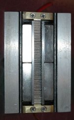
DIY 4 Inch Ribbon Tweeter
- By fooeywuffle
- Planars & Exotics
- 26 Replies
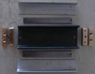
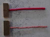
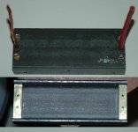
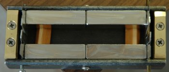
Here is info on the tweeter I made. It has 4 5/16 inch long magnetic part and ribbon is 3/8 inch wide. .03 ohms for pleated ribbon. This is quite a project to make the parts. A lot of cutting, filing, drilling, and tapping. The 1/2 X 1/2 X 2 inch magnets are the N52 which is the strongest I could find. Since it is high current, the wires are large and soldered into deep holes in the brass part. Top part is thick so will press on ribbon evenly. One end is insulated from steel part. When done and has a good ribbon, will have an aluminum screen cover. So far testing things, I have destroyed 3 ribbons. One to measure the resistance, one when I hooked it to transformer at full volume, that was ear splitting! One jusr wasn't right, so rubbed. Hard to get one straight. I don't know if kitchen foil is really any good for this. Seems stuff a little tempered would work better.
Attachments
ICEPower 50ASX2 BTL
Hello there,
I have an ICEPower 50ASX2 in a Fender bass amp that gave problems.
After a very close look I found two burned smd parts, FE100 and FE101.
I assume they are coils or the like.
After these "coils" we find the connector P103 (+/- 24V DC).
The fuses are ok.
I first tried the other pcb's with an external supply connected to the cable going into this P103 connector.
All worked as intended and no excess current is drawn.
So I replaced the FE100 and FE101 with a piece of wire and reconnected everything.
The amp works flawless now.
But still I want to replace FE100 and FE101 with the correct parts.
Here my question:
Is there anybody who can tell me what the correct parts could be?
ps:
IcePower and Fender can't tell me what parts are used?!
Schematic of the Ice module? No way!!!
I allready asked for it.
Best way to do the PSU chassis grounding
- By tanwa
- Power Supplies
- 5 Replies
Hello
I am building the upgrade DC power supply for DAC in separate chassis. It consist of 2 set of power supply, one for digital and other for analog. they have separate ground.
The problem I concern is, how do I connect the chassis ground at the PSU chassis to avoid ground loop? I thing the ground of each set of power supply will be connected some where in the DAC, and if I connect the ground of each power supply together at the PSU chassis, may it cause the ground loop?
or I just put only one set of digital ground or analog ground to PSU chassis.
Which is the best way to go?
Thank you
Tanwa
FS - Troels Gravesen Fusion passive loudspeakers - UK
- By gordonewen
- Swap Meet
- 6 Replies
NOW SOLD
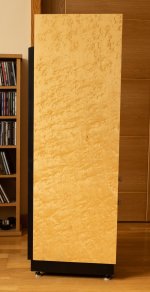
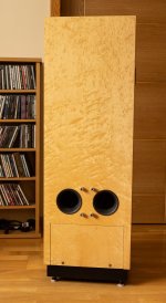
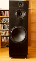
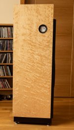
I have for sale a pair of Fusion passive loudspeakers (level 1 kit) that I made 18 months ago. Price £1500. They are finished with Birds Eye Maple veneer and satin black paint on the front baffle. Here is a link to the TG website for these speakers:
Fusion
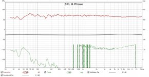
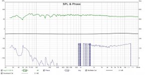
Lovely sound with deep bass with a lovely tone. I've attached frequency response graphs that I measured with REW and a calibrated mic, they are unfiltered. I offer them so you can see that they respond as expected; the low frequencies are probably affected by the room to some degree but the overall response is good. I guess all diy'ers know that the sound quality will be comparable to commercial speakers costing much, much, more. At the Ascot hifi show last November I listened to £20k speakers that I didn't think were as good, but that's just my opinion!
Collection only.
Auditions are fine with me if you are near Sandy, Beds.
I have for sale a pair of Fusion passive loudspeakers (level 1 kit) that I made 18 months ago. Price £1500. They are finished with Birds Eye Maple veneer and satin black paint on the front baffle. Here is a link to the TG website for these speakers:
Fusion
Lovely sound with deep bass with a lovely tone. I've attached frequency response graphs that I measured with REW and a calibrated mic, they are unfiltered. I offer them so you can see that they respond as expected; the low frequencies are probably affected by the room to some degree but the overall response is good. I guess all diy'ers know that the sound quality will be comparable to commercial speakers costing much, much, more. At the Ascot hifi show last November I listened to £20k speakers that I didn't think were as good, but that's just my opinion!
Collection only.
Auditions are fine with me if you are near Sandy, Beds.
Attachments
Output Inductor
So I have a Hifonics BRZ 1700 that has been repaired.
When I look at a sine wave on the output and I gently twist the output inductor it seems to shift 180 degrees out of phase. When i let go it pops back.
Took inductor off the board but cannot find a short. Re-installed and same thing.
Any ideas?
When I look at a sine wave on the output and I gently twist the output inductor it seems to shift 180 degrees out of phase. When i let go it pops back.
Took inductor off the board but cannot find a short. Re-installed and same thing.
Any ideas?
JL 1000/1 Input Issue
Amp is mono with 2 rca inputs. When I hook up one rca i have a distorted ouput. Hook up both inputs and the distortion goes away.
2 2068 IC's on the initial input stage, seem to be ok.
2 2068 IC's on the initial input stage, seem to be ok.
Help with adding tweeter to vintage speaker.
Hi everyone. I got a pair of home built speakers with vintage speaker drivers inside. At first they didn't sound so good but i made them open back and now they sound absolutely amazing. These are my favorite speakers to listen to music. They have so rich and clean sound.
In the boxes are DEW magnetfabrik Dortmund 6x9 speakers but they just lack high frequency. So my question is how do i go about adding a tweeter to vintage speaker. And what about a crossover, i don't want to spend a lot of money on the tweeters and crossover because i got speakers for next to nothing. I can provide videos and pictures for driver identification if needed.
In the boxes are DEW magnetfabrik Dortmund 6x9 speakers but they just lack high frequency. So my question is how do i go about adding a tweeter to vintage speaker. And what about a crossover, i don't want to spend a lot of money on the tweeters and crossover because i got speakers for next to nothing. I can provide videos and pictures for driver identification if needed.
Resistors across speaker terminals
hi all
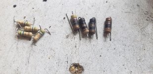
I have this boss PF1800 class AB amplifier. Found no damage on outputs or power supply but just resistors across speaker terminals burnt. I think they are 4.7ohms. I have 5.6ohms in stock. Can I use this instead and what will be the reason they got burn in the first place. The 104j caps are good found no short. Is there anything that I need to focus on?
I have this boss PF1800 class AB amplifier. Found no damage on outputs or power supply but just resistors across speaker terminals burnt. I think they are 4.7ohms. I have 5.6ohms in stock. Can I use this instead and what will be the reason they got burn in the first place. The 104j caps are good found no short. Is there anything that I need to focus on?
Attachments
Yet another mux, 4052, 4053 or 4066?
- By youssefaly97
- Analog Line Level
- 93 Replies
Hi I'm building an audio mux with volume control using a couple of digital potentiometers.
The digi-pots require the signal through its pot connections to be between GND and VCC which is 5v so I decided I will raise the audio input ground to 2.5V with an op amp or maybe an LM317 regulator.
I will connect the digi-pot as a regular potentiometer, the input at one end, the ground at the other and take the output between the wiper and ground only that the input and output signal ground to this digi-pot will be the 2.5V reference line. The audio signal is AC coupled and dc-shifted to the same 2.5V line.
SWITCHING:
I have several options to try to switch the input audio,
1) use a whole 4066 for each audio channel, that is one 4066 for the left channel & another for the right, that's for each input channel. Each channel is a "T", two switches in series, and the connection between them is connected through another switch to the 2.5V line. Adv: When I disconnect this channel, it looks like 100M ohm in series with another 100M input to output and 125 ohms to 2.5V between them. Disadv. takes lots of board space (not a big problem), cost doesn't matter.
2) use 4052 for all 4 stereo inputs, Adv. small board space but I need HELP here, I want to achieve the same effect of connecting the input to be disconnected with the reference line instead, if VCC is at 5v and VSS at 0, can I connect the VEE to the 2.5V or does it have to be below VSS?
3) use 4053 and switch the audio input with its reference; L, R & Gnd but still may need to connect VEE to 2.5V
Frd / Zma to ltspice - a simple tool
- By Leffemannen
- Software Tools
- 3 Replies
FRD2SPICE is a little tool that generates a spice model from frd / zma files that I wrote a couple of years a ago. (It generates a .SUBCKT netlist.)
I thought I'd share it here in the hope that might be useful to others as well ho like to do xover simulation in ltspice. (Or any spice variant that supports frequency tables really.)
The generated model is implemented using frequency tables and voltage / current sources. It's intended to be used for .ac analysis (frequency response).
The tool will ask for 5 files:
Spice file: name of the .lib file to be generated.
zma file: Impedance data.
3 frd files: Typically one on axis + two off axis files (the last two are optional. Just click cancel if you don't want to use off axis data.)
Files included:
FRD2SPICE.exe: The tool it self. An enormous 10Kb file... You may have to run it in compatibility mode on windows 8.1/10 because i originally wrote it for windows 7 32bit.
SpkrTbl.asy: Ltspice speaker symbol, it takes two parameters: driver name + DeltaX (acoustic centrer compensation in meters, usually = 0)
Dayton2way.asc: A simple example project to get you started.
Some .frd & .zma files: used in the above project.
Enjoy!


View attachment FRD2SPICE.zip
I thought I'd share it here in the hope that might be useful to others as well ho like to do xover simulation in ltspice. (Or any spice variant that supports frequency tables really.)
The generated model is implemented using frequency tables and voltage / current sources. It's intended to be used for .ac analysis (frequency response).
The tool will ask for 5 files:
Spice file: name of the .lib file to be generated.
zma file: Impedance data.
3 frd files: Typically one on axis + two off axis files (the last two are optional. Just click cancel if you don't want to use off axis data.)
Files included:
FRD2SPICE.exe: The tool it self. An enormous 10Kb file... You may have to run it in compatibility mode on windows 8.1/10 because i originally wrote it for windows 7 32bit.
SpkrTbl.asy: Ltspice speaker symbol, it takes two parameters: driver name + DeltaX (acoustic centrer compensation in meters, usually = 0)
Dayton2way.asc: A simple example project to get you started.
Some .frd & .zma files: used in the above project.
Enjoy!
View attachment FRD2SPICE.zip
is there a standard iso fitting bearing/spindle turntable?
- By Voorhuib
- Analogue Source
- 1 Replies
easy question, is there a standard iso fitting bearing/spindle turntable?
Like H7/f7, G7/h6, J8/h7?
Standard sintered bronze bearings are all H7 fitting and I think that's to big...
thanks
Like H7/f7, G7/h6, J8/h7?
Standard sintered bronze bearings are all H7 fitting and I think that's to big...
thanks
Can anyone help me with this amp will not power on
It’s a Rockford Fosgate punch 150 the problem is wont power on I hear a clicking sound in the transformer and the led has dim blink going on. I’ve already replaced the D44 power supply transistors and LM339 with a new one no luck.
Attachments
Hypex SMPS1200A400 measurements
- By capslock
- Power Supplies
- 4 Replies
I had the chance to measure above power supply.
First of all, I measured the rail voltages with a true RMS meter. They came out as +/- 63.1 V. I then loaded the negative rail with a 66 R power resistor. Voltage dropped to -62.3 V (forgot to measure the positive rail) within about 10 s. Loading with 33 R caused a drop to 61.7 V, but this was within about 1 s.
For comparison, the Hypex TR400 toroidal with 2x 10000 µF dropped from 61.7 V to 57.0 V with 66 R and to 54.05 with 33 R.
Ripple data to follow...
Buffalo II clips on 0dB Test signals
- By Salar
- Twisted Pear
- 0 Replies
Hi, I am using the YEDS-18 test CD, standard for compact disc player alignment.
Signals like a 1000hz sine or 100hz sine at full scale heavily clip
on the Buffalo II. So will music.
Now one could say that overshoots in 0dB test signals
were unknown back then.
But any other player plays the YEDS-18 fine.
And, most important:
The clipping is not always there.
Switching off the Buffalo off and back on sometimes helps.
Then the test signal will me played fine.
So something erratic must happen,
when the Buffalo II/ES9018 initialises during powering up.
Input is tranformer-isolated SPDIF and the clipping is
definately in the digital realm.
Best,
Salar
Chapter 2 - Rolecor RTA-650 receiver - revisited....a (2S)C727 replacement?
- By 62vauxhall
- Solid State
- 14 Replies
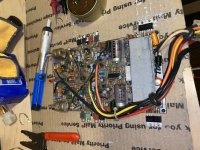
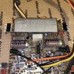
A continuation of my previous thread, Rolecor RTA-650 receiver - revisited. But will bypass those details. I am failing to solve a problem or discoveed another, and I am hoping for additional, insightful advice.
Where I am at now is BD139 & BD140 driver transistors are installed. They are in place of KSA2690 & KSA1220 which themselves replaced original 2SC497 & 2SA497 as one of the latter was faulty.
Newly received output devices are in place as well, MJ21194.
After each transistor installation, I powered the receiver up with a DBT and each time, the bulb settled to a dull glow. Once all were installed, I tried listening to the receiver but still have a dead channel - the right one.
Before installing the BD139 & BD140 pairs, I was getting 53 Volts at each leg of the transistors preceeding them. And I am still getting that voltage now.
Looking to an "upstream" component, I checked a TO18 transistor in the affected channel and it reads as bad. It's counterpart in the other channel does not display the same fault.
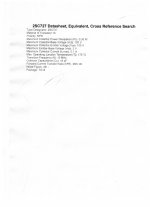
The number is C727 - presumably 2SC727.
So far, my searching has not hit on any situation involving that transistor. I did find a data sheet (attached) but when entering specs on Digi Key's part finder, which is just guessing on my part, no results resemble what I think I'm looking for.
Since a C727 is NPN, I don't suppose BD139's that I ordered extras of would do?
Where I am at now is BD139 & BD140 driver transistors are installed. They are in place of KSA2690 & KSA1220 which themselves replaced original 2SC497 & 2SA497 as one of the latter was faulty.
Newly received output devices are in place as well, MJ21194.
After each transistor installation, I powered the receiver up with a DBT and each time, the bulb settled to a dull glow. Once all were installed, I tried listening to the receiver but still have a dead channel - the right one.
Before installing the BD139 & BD140 pairs, I was getting 53 Volts at each leg of the transistors preceeding them. And I am still getting that voltage now.
Looking to an "upstream" component, I checked a TO18 transistor in the affected channel and it reads as bad. It's counterpart in the other channel does not display the same fault.
The number is C727 - presumably 2SC727.
So far, my searching has not hit on any situation involving that transistor. I did find a data sheet (attached) but when entering specs on Digi Key's part finder, which is just guessing on my part, no results resemble what I think I'm looking for.
Since a C727 is NPN, I don't suppose BD139's that I ordered extras of would do?
Attachments
82 rectifier 2.5V filament not heating
- By sidn28790
- Tubes / Valves
- 11 Replies
I have a pair of 82 rectifiers that take 2.5V for the filaments. My OPT filament AC supply is 5V. So, I took a pair of matched resistors and dropped the 5V down to 2.5V (see schematic attached). The pair of resistors was done on both legs of the AC supply. Without the tube in the socket, this tested OK at the socket pins. 2.5V dead on. Then, I insert the 82 rectifier into the socket and there is no heater voltage. 0.0V measured again at the socket pins. the 82 rectifier does not heat up. I tried this on 2 tubes, but NOS, and neither is heating up. Both tubes have good continuity between the filament pins. Note, only the filament voltage is being applied. No B+, as the rectifiers need to warm up (mercury) prior to B+.
Thoughts?
Thoughts?
Attachments
FS: SB Satori Kairos + Woofer module 3 way drivers
- By fishball79
- Swap Meet
- 6 Replies
I have a set of brand new in box SB drivers meant for the Jeff Bagby's Kairos speaker and the woofer module to let go.
USDXXX for the set. These are better suited to be sold in asia as they are in Singapore.
PM me for shipping.
Satori TW29R x2
Satori MW16P-8 x2
SB9NRX75-6 x2
USDXXX for the set. These are better suited to be sold in asia as they are in Singapore.
PM me for shipping.
Satori TW29R x2
Satori MW16P-8 x2
SB9NRX75-6 x2
2 fold BIB for Tang band w4-1320
- By morpheus82
- Full Range
- 11 Replies
Hi all,
I have 2 TB w4-1320 laying around and I want to build 2 floor standing speakers for my tv.
I have 97cm in height, (make it 40 inches for the US folks), and I'd like to try the BIB.
I downloaded the sheets from Godzilla(thanks man!) And I need a 2.25m line, with an output surface of 310cm2, with the speaker placed at 50cm from the start of the line.
Now, don't have enough height for the standard bib.
So I need to fold twice, but I also want the speaker to be as high as possible, ideally at the top of the cabinet.
So I came up with this solution in the picture.
15971313270311342493500824927051 — ImgBB
As an idea, is it correct?
Any drawbacks of I maintain the original shape of the "tall" bib?
Thanks in advance!
first build - near field computer speakers
- By 4heid
- Full Range
- 9 Replies
I have been watching the forum for years and recently unloaded all of my audio equipment in hopes of doing something more interesting in the DIY space.
I am most interested to build the following first:
1. Near field monitors from a single full-range driver for my computer, est. distance from my ear would be 30" and positioned on top of my monitor. I have no desk space for them so they will be mounted pointed slightly downward towards me.
2. Limited volumes due to it being for use during my workday and in a small room, about 9x9'. Thus, I want to have the 'loudness' effect at low volumes whereby bass is present without increasing the power input.
3. Thus far focusing the efforts on using a MarkAudio 7ms.
4. The box cannot be any bigger than about 5L due to the mounting requirements about the monitor which is about 12(w)x4(h)x8-10"(d). I am expecting them to be longer horizontally and rectangular.
I have run through some simulations but have limited experience. Thus far they seem to be telling me its going to be hard to get a low bass frequency in that size. The best seems to work out with a tune around 70-80hz.
I have been considering a transmission line design and would be very interesting to hear the difference they may make vs a standard port.
I would appreciate any opinions on the possibilities of the objectives and perhaps some help on design options that fit or someone to tell me that there is a better driver fit or that I am out of my mind, at which point I will want to try even harder to be creative with this need.
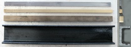
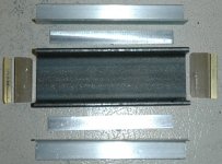
Nice aluminum CD adapters 1" to 2"
Picked these up somewhere along the way and haven't used them yet so it's time to let them back in the wild.
When I got them I drilled the 1" side to accommodate the 2 hole Altec bolt pattern. This was professionally done on a Bridgeport mill by a tool maker (Me).
Flange Dia on the 1" side is 3.9" with the Altec 2 hole bolt pattern and another bolt pattern with 3X 1/4" holes drilled on a 2-1/4" bolt circle.
Flange Dia. on the 2" side is 4.7" with 4X tapped holes on a 4" bolt circle. Holes are tapped either 1/4" fine thread or 6mm. To lazy to check at the moment but can do if it's important. There is a lot of room to add your own bolt pattern if your so inclined.
Overall length is 3" so the expansion rate (cone angle) is not as abrupt as most adapters I've seen. Heavy cast aluminum construction but there is no indication of the manufacture on them. Probably had stickers at one point.
Asking 50 bucks plus shipping from NJ. Shipping to US only. Pictures upon request.
BillWojo
38,000lm Bulb: Now Help Me Build The Best Projector Around It
- By vanguard2020
- DIY Projectors
- 0 Replies
I have a 1,200w/38,000lm sylvania bulb, now I need help building a nice projector around it. Here are the details to work with:
1. I'm in Africa, with a few box stores, but no RadioShack-type outlets. I can order stuff from ebay...and I can have small items (fresnels/front lens/etc) FedEx'd in time for the project to be completed by its deadline (Sept 14th). I have $1,000 to work with.
2. I also have a Chuwi Hi9 tablet with 2560x1600 screen. Could this be used with a set of fresnels? Or would it be best to get a flat panel lcd monitor from the local big box store? (Note: I'm in Africa, and there aren't RadioShack type stores.)
3. Size is not a worry, a long as the finished product can fit on or in a small car. Also, the project will only last a few days, at most. In fact, this might only be used for less than an hour. But it needs to be the BEST it can be for that hour. 🙂
4. I'll be projecting onto a med/large building, maybe 200'x200'.
Finally, I can probably find an old slide projector and/or overhead projector for lenses and fresnels . . . but if something ordered from eBay can outperform those, great. I'm looking to make the projection sharp and colorful, and if some items need to be sent from the states, ok.
I've already checked into used projectors. Some are great, like the stackable NEC stuff..but anything 10,000lm+ just weighs too much (50lbs-ish) and the shipping would probably break the budget. If I'm wrong, I would gladly have a 10,000lm+ projector sent here, and avoid the DIY'ing.
Look forward to any helpful tips! Innovative ideas very welcome!!
-jc
Anyone have a schematic for a Forte 4a?
- By milosz
- Solid State
- 3 Replies
I'm doing a repair on my Forte 4a, would appreciate any schematic that anyone out there can provide.
Sanyo DCX6000K restore - Transistor replacements needed!
- By joocfpinto
- Solid State
- 3 Replies
Hello everyone!
I currently own a Sanyo DCX6000K with a problem in the main power amplifier section. This stereo receiver has two amplifiers (one per channel), one of which is giving random high volume noise spikes on the correspondent speaker while the other channel works perfectly.
Some tests/repairs I've done:
- This happens even without any volume on the receiver.
- I've tested the faulty amplifier outside the receiver powered with a dual power supply (with the input grounded): same thing happens on the speaker.
- I've replaced all caps with new ones.
- I've already tuned the amplifier bias with the help of the same dual power supply current measurement. Any time a noise spike occurs there is a current spike as well (which is obvious), and the current bias stabilizes when no noise occurs.
- I've replaced the output transistors 2SA764 and 2SC1444 with original ones (found from eBay).
I'm looking forward to replace the remaining transistors of the board, but I need advice on replacements for them:
- 2SA733 PNP
- 2SC875 NPN
- 2SC1175 NPN
- 2SA659 PNP
- 2SA532 PNP
The schematics may be found after login in the HiFi Engine site, for example. The faulty board reference shown on the schematics is 131-0-4001-33001.
Any help is welcomed!
João
nice PCB connectors for signal, please?
Hi fellow builders
I'm after nice, practicable, affordable connectors for my amp- and preamp-projects... that is, signal-connections as in "wire-board" as well as "board-board".
There are plenty at the usual suppliers, but I'm a bit lost because of the many variables to look for, and a lack of relevant experience?
obviously important are
- connection-quality
- signal-integrity
- ease of use
- price & availability
of course, if there was something that is looking good it'd be all the better.
thank you!
david
Ground Zero GZPA10000SPL problem
- Car Audio
- 2 Replies
I am repairing a ground zero 10000spl.
It was initially using IRFP360LC, but I decided to use FDA24N40F.
Usual problems, output mosfet in short (only in one of the 4 stages) broken driver board and perfect power supply.
I did the usual tests:
1) perfectly fixed the driver board
2) checked all gate (33r) and pulldown (100k) resistors, all perfect, but for safety I changed them.
3) checked the 4 resistors of VB (4,7r) all perfect, then I left them in their place.
4) to the eye there do not seem to be short circuits or shorted turns in any of the 4 inductors.
5) I detect all the low sides and with the help of an auxiliary 12v source (small battery) I also detect all the high sides, so everything is fantastic.
6) after fixing everything, I mounted only 1 IRFP360LC for each side (of each stage) using different production mosfets (but it was only a test) and the amplifier immediately started regularly showing a correct switching frequency on all four the stages, only that some mosfets warmed slightly (which could be normal, since I only used one per side and in addition, the mosfets were not all identical).
7) I remove the test IRFP360LC and install 1 brand new FDA24N40F per side (for each stage), I turn on the amplifier, but unfortunately I see that the amplifier does not start, that is, the frequency of RAIL TO RAIL, appears and disappears intermittently , as if it started and stopped all the time.
8) I remove the FDA24N40F to do some tests, but nothing has changed, everything is like in point 5, only now, I have reinstalled FDA24N40F but this time some output mosfets are shorted, so now I am forced to rework the driver board, what a great waste of time.
Anyone have any advice for me?
No GUI on Yamaha RX-V3800
- By tojoko
- Solid State
- 6 Replies
Hi
Just bought a second hand RX-V3800, that is working OK, just can not change any settings, because the GUI is not showing, on any of the Monitor Out sockets, does anyone know how to solve that, I am using the Receiver in 8 ch, multiple input mode, in an active set up, like I said that works very good, just curious why no GUI,
Cheers, Tom.
IEC Socket w/switch and front LED recommendations
Finishing up my parts list and cutout diagram for a 6 channel Hypex build. Need thoughts/input on the following:
1) To keep things simple, I was thinking of using an IEC socket with a built-in On/Off switch and Fuse. I found one on Parts Express but it says it can only handle a 6A @ 250v fuse. I will be on 110v and wanted to plan on the combined continuous rating of the Hypex's which would be 900w. So I thought a 10A fuse would be best. Any other recommendations to look at? Or is my math wrong and this socket would be fine?
2) What is the easiest way to add an LED to the Front Panel for when power is on? I will be using a 12V trigger assembly so my pre/pro will turn the amp on/off. I would assume I could splice 12v power off the trigger?
Thanks!
Blaupunkt 12" for under $30 - 8 of these good for an infinite baffle build?
- Subwoofers
- 20 Replies
link to product page of this driver: BLAUPUNKT: Subwoofers
There's a place that sells these for under $30. I'm thinking of buying 8 of these for an infinite baffle build. To me it seems like this would be the best sound-for-the-buck build you've ever seen. Please disprove me because I can not hold off from buying these now.
Are the specs on this sub good? Are the specs good for an infinite baffle build?
Increasing subwoofer impedance
- By Stallion63
- Subwoofers
- 23 Replies
Can a 4 ohm resistor be used to increase a 4 ohm subwoofer to make it 8 ohms? I heard that it would lead to boominess. Can someone help?
Need help picking an amp
Hi All,
I've been itching to build a Nelson Pass amp for a couple of years now, but I'm hesitant to pull the trigger on any particular kit since I'm new to this and have limited time and budget to try them all (though am not all that new to electronics). I also may need a reality check to know if any of the current offerings will even meet my needs. I've never heard any of these in person, nor any low watt class A amps. So, not exactly sure what to expect. I'm hoping you could help me pick an amp that'll fit my needs, or maybe even dissuade me if in fact none of them will meet my needs. I just really like the idea of building a world-class type amp with my own hands.
A little background. I currently have a home theater setup with Elac towers (~87db sensitivity, 6-ohm nominal) that I'm looking to pre-out the front channels to a higher fidelity amplifier. My primary music source is through Raspberry Pi -> USB DAC. This setup would be temporary, as I hope to build a dedicated 2-channel system in another room of the house in a couple of years, using the newly built amp and high-sensitivity DIY speakers that I also hope to build in the future. The HT receiver does have an SVS sealed sub, in case that matters.
Music and preferences
My primary listening habits include classic rock (Pink Floyd, Rush, Led Zep, Police, Dire Straits), and electronic/post rock/alternative/indie (Kraftwerk, Foster the People, Mutemath). I sometimes listen to other acoustic stuff like folk and jazz.
Preferred sound signatures: airy, detailed, wide soundstage, clear instrument separation, black backgrounds, great imaging. Somewhat forward and fun without being fatiguing, forward vocals and midrange, with slam and presence. Warmth, but not muddy - just a little bit lush.
I don't listen at extreme loud levels, but maybe a "comfortable" loud that will fill a 17x17 open room with sound - comfortable loud as in too loud to carry on a conversation with someone in the room, but not so loud that it is uncomfortable to sustain for more than a couple of songs. Are the Pass builds the way to go for me? If so, which one would you suggest, given my music choices and listening preferences?
Thanks!
Thad
Internal panels to separate circuits
- By Jaytor
- Analog Line Level
- 9 Replies
I am building a preamp and I'm wondering about the benefit of including internal aluminum panels to separate the audio circuits from the power supply and digital circuits.
The preamp will have two toroidal transformers with steel covers, regulated power supplies, and also an OLED display board.
There is only an inch or so (~30mm) of space between the power supply boards and the audio circuitry. Maybe 6 inches (150mm) between the OLED board and audio boards.
Is there any benefit adding aluminum panels in between these circuits. I'd obviously have to fish some wires/cables through/under the panels, but otherwise the spaces could be completely separated.
Thanks.
Questions on 5V Power Supply for RPi and DAC
- By bbingert
- Power Supplies
- 5 Replies
I hope that this is not too ridiculous of a post. I’m just getting to the stage of thinking I know enough to be dangerous.
I’ve just built an F5 amp and am now starting to upgrade the upstream components. First on the agenda is a Raspberry Pi based streamer with a separate DAC HAT, most likely an Allo Boss. I currently trying to decide how to power this setup. There are obviously a lot of power supplies available, but since I’ve got some time on my hands, I thought I would try to build one.
I’ve gone through a lot of threads regarding DAC power supplies and tried to distill the data / opinions as much as possible. With regards to power supply noise, it seems like “low noise” is good, but “ultra-low noise” may not make much of a difference practically. This seems reasonable given that the DAC has filters to further reduce power supply noise and the RPi creates enough noise internally to overwhelm any from the power supply.
In the thread on the Shanti Power Supply, there was a lot of discussion on load transients and having a significant amount of capacitance at the output to deal with these transients. The prevailing opinion seemed to be that this had an impact on both measurements and perceived audio quality.
Putting that together, I’m thinking about building the attached circuit. The basic design ideas were:
• Single Rectifier into a reasonable capacitor bank (3000uF) to drop ripple somewhat and keep supply voltage above the dropout of the succeeding regulators.
• Separated regulator / filter circuits for RPi and DAC fed by the single unregulated supply.
• 7805 regulator with the datasheet implementation of the high current regulator with overload protection. This should provide more than enough power for the device and the overload protection will limit the inrush current when charging the succeeding capacitor bank.
• A lot of capacitance on the output of the regulator, both for bulk storage and decoupling. The capacitor bank will include one 1F supercapacitor (581-SCMR22G105SRBA0), 2000uF of Electrolytics and 10uF, 1uF, and 0.1uF decoupling caps.
I’ve got a couple of questions before I tackle the build and was hoping to get some input.
• I realize that over 1F of capacitance at the output is crazy, but has it passed crazy and transitioned into stupid? The supercapacitor costs ~$5, so it’s not going to impact cost too much as long as it won’t have any negative effects on power quality.
• Is the balance / amount of electrolytics about right?
• Is there something else that I’m completely missing?
I’ve attached a schematic of my idea. Any input is appreciated.
Proton (NAD) 520 - replacement part
- By Westy37
- Solid State
- 8 Replies
Hi all, I'm generally a speaker builder so have come over here for some advice. I need to replace the volume pot in my Proton-520 integrated amplifier.
I bought it a while back and it looked as if it had been dropped at some stage as the volume knob had a chunk missing out of it. I tried replacing it with a standard log pot but then realised that the pot has an extra tap (so it has four legs). I'm guessing this is for the loudness button or something. Anyway, the volume is far too sensitive as it is at the moment with a regular three pin pot and the other lead left taped up so I was hoping someone could direct me to a replacement part for the volume pot. Unfortunately I can’t find the original pot so I have no way of determining what the extra leg was connected to at the pot end.
You can see the pot in the bottom right hand corner of the picture. There are two white wires run to it which correspond to each of the channels as the silkscreen on the PCB says x and y next to the pot and also where these wires are connected to the pcb.
I've attached a couple of pics of the amp (not my unit) and the service manual.
Please help me out!
Cheers.
Attachments
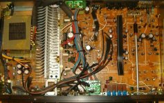
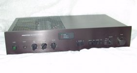
FS - USB-GPIB-HS adapter.
I have a couple of these, which I'll let go for competitive (China seller) ebay pricing. I'm in the US. PM me if interested.
NI now has the free LabVIEW "Community edition" which I assume will work with this product. Unfortunately for me, my only GPIB instrument no longer responds to its GPIB interface, so, no need for the GPIB interface anymore.
I'll give it a couple week, then put them up on ebay. Thought I'd give folks here first dibs, if anyone;s still interested (last time was 2016)
Jobsite stereo audio setup question
- Everything Else
- 27 Replies
Hi everyone,
I have a bunch of music from cd's stored on a USB flash drive that I want to listen to on my Bosch PB360C Jobsite Stereo. The Bosch has a 3.5mm AUX input jack and can also be paired with a Bluetooth enabled playback device. My question is, what is the simplest way to connect the flash drive to the Bosch so I can access and listen to the music files on the flash drive? What hardware and/or cabling options would work best for this application?
Thanks for any and all suggestions!
looking for a fisher 800c output transformer
hello,
does anyone have pile of 800c parts or an 800c in a pile?
I have an 800c in the UK that is a lovely thing but has been a) bodged and b) dropped. We are working through it but need the speaker selector knob, 3 sliders, but mainly an output transformer... T991-116-1C
I'm in the UK but happy to sort out a way of getting it here from the US...
thanks!
alex
Zener diodes replacements
- By turboyam
- Solid State
- 9 Replies
I have to replace 2 different zeners on an amp board and, replacements are hard to find. The originals were: WZ-280 and WZ-197
Found NTE5034A and NTE5029A but even those are hard to find!.
I always get stuff from Digikey Canada but, they have nothing like these in stock.
Any ideas???
Found NTE5034A and NTE5029A but even those are hard to find!.
I always get stuff from Digikey Canada but, they have nothing like these in stock.
Any ideas???
Preamp outputs - balanced > SE output?
- By gilphilbert
- Analog Line Level
- 6 Replies
I'm building my first preamp and I'm just coming to the output stage. I'm new to this, so I'm trying to work out the best approach. The end goal is to have balanced end-to-end, but currently my power amps are single-ended so I need the flexibility to have both outputs.
Is it better to use a simple XLR>RCA convertor (that connects pin 3 to pin 1), or would it be better to integrate a balanced>SE stage at the end of the preamp that allows for both balanced and SE output? I've seen very conflicting information, but most of that comes when conversion isn't possible (i.e., someone is buying pre-built components)
I'm assuming that I could simply put the balanced output to the XLR connectors then tap into those connections (on a PCB) as the inputs for a conversion stage, maybe something like the Project 87 opamp-based balanced>SE stage.

I'm just wondering if I'm over-engineering this due to my enthusiasm 🙂
Is it better to use a simple XLR>RCA convertor (that connects pin 3 to pin 1), or would it be better to integrate a balanced>SE stage at the end of the preamp that allows for both balanced and SE output? I've seen very conflicting information, but most of that comes when conversion isn't possible (i.e., someone is buying pre-built components)
I'm assuming that I could simply put the balanced output to the XLR connectors then tap into those connections (on a PCB) as the inputs for a conversion stage, maybe something like the Project 87 opamp-based balanced>SE stage.
I'm just wondering if I'm over-engineering this due to my enthusiasm 🙂
Improve loudness on Samson SR950
- By adikumar2010
- Headphone Systems
- 7 Replies
I got Samson SR950 they sound fine , no issue with quality but the problem is the output is low from my PC motherboard. How can I make them sound louder? I don't want to spend more then $50-60. I just listen to music and play games I am not into any studio stuff.
I saw some amps but they are tiny portable rechargeable but I will be using headphones on my desk so I can get proper amp with wall adapter. I assume full size amp will be better then those small portable ones and you don't have to recharge them.
I don't know what will be better an Amp or PCIe sound card or DAC/amp combo or something else.
Marantz CD-63SE replacement laser problem
- By rmparker
- Digital Source
- 18 Replies
Hello,
First post here so hello to all.
My Marantz CD-63SE was skipping quite a bit, so I bought and have installed a replacement VAM1202. Tested with three CDs all of which would not play well before, and all three played through perfectly. I was very happy.
But - the fourth CD - the player could not detect. Nor a few others. In fact only about 50%.
So, I tried adjusting the pot on the laser assy. Some improvement but still not perfect. Then I tried adjusting the two tiny torx screws as suggested on the CD63-67 thread on here. Again, some improvement, but still only about a 75% success rate. The "old" laser assembly never had this problem, it read any CD I tried, just often skipped during playback.
The seller of the replacement laser suggested "adjusting the servo" but has not explained what that means. Also he says that there is no chance the VAM1202 is faulty, which contradicts what I have read on here that some boards are duff on arrival!
So, can anyone please give me any advice on what to try next?
Many thanks,
Richard
Tuning my Tannoys (Definition Series D500)
When fixing one of the bass speaker surrounds, as described here, I also had a closer look at the crossovers and the internal wiring - and I was not too happy with what I found. (Shifting from 'repair' to 'modification', I considered it's better to start a new thread.)
A bit of history: I had bought those speakers around 2002 / 2003 from a small dealer who claimed to have modified the original crossovers and had used those speakers for demo in his shop for a while. The price was reasonable, sound was great.
Now, more than 15 years later, they still sounded great. This is true for use with a pair of Quad II (early 1960s), which I used until January this year, and even more now with my newly restored Quad 303 in combination with a Rotel 1570 preamp.
But looking at the internal wiring I could not resist to think: there must be more in store, soundwise!
What I found were 'van den Hul M.C. CS18' halogen free cable. van den Hul website states that these are 0.56 sqmm 7-strand silver coated copper, and they recommend these cables for tweeter use. These cables were used for all internal connections between crossover and speakers.
Looking closer, the silver coating seemed to be corroded where the cables meet the cable shoes.
Next, the crossovers. Just look for yourselves! In my early years, as an apprentice, my boss would have thrown me out of the lab if I had delivered something like this, even as a prototype.
What to do next? I can see a Mundorf capacitor, and an air core inductor, which add to my confidence. I decided to leave the crossovers unchanged for the moment and focus on the wiring. 0.56 sqmm for bass and mid range - I doubt that this is appropriate.
Attachments
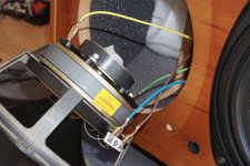
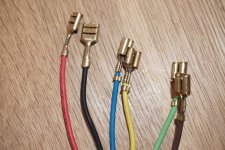
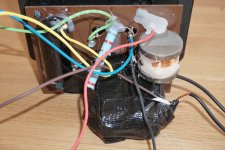
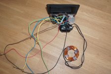
Interpreting rectifier data sheer ratings
- By deafen
- Power Supplies
- 3 Replies
Due to the combination of parts I have on hand and on order, I'm considering using a hybrid bridge rectifier using SS diodes and the uncommon 12Z3 tubes. (12Z3 data sheet)
The PT is rated for 325mA@243Vrms (no CT available). I'm only going to be pulling a constant 140mA, so I expect my loaded voltage to be at least in the 260-270 range.
The datasheet says PIV is 700, but max plate voltage is 235Vrms (330Vpk). It also says max steady-state current is 330mA, but max output current is 55mA. Oh, and it gives a rating for max voltage drop at 110mA. And then the drop curves go up to 185mA.
So which of these maximums actually apply in my situation? I'd like to feed them around 260-270V, pulling about 140mA through a hybrid bridge to a capacitor input. Am I abusing them? If so, am I asking for fun fireworks, or just shorter tube life?
Specs for Philips AD 11600 T8 tweeter
After digging through my parts stock, I realised that I have 2 unused units of the said tweeter, probably purchased more than 10 yrs ago. I intend to use these in a 2 way system. However, the tweeters do not come with any documentation, other than in a cardbox box.
Is there anyone who can assist me to get the specs for these tweeters? I have searched the internet for the specs, but it was fruitless.
Thank you very much in advance.
VK Wong
Is there anyone who can assist me to get the specs for these tweeters? I have searched the internet for the specs, but it was fruitless.
Thank you very much in advance.
VK Wong
Fs: BPPBP PCBs
Due to a project chance, I am herewith selling 3pcs empty PCBs for the well regarded BPPBP - Bruno Putzey's Purist Balanced Preamp:
BPPBP - Bruno Putzey's Purist Balanced Preamp (well a balanced volume control really)
12 euro each + expenses.
BPPBP - Bruno Putzey's Purist Balanced Preamp (well a balanced volume control really)
12 euro each + expenses.
Load more
Projects by fanatics, for fanatics
Get answers and advice for everyone wanting to learn the art of audio.
Join the Community
507,812
Members
7,889,474
Messages