Are GR Research kits really as good as people say?

Hey all. I'm considering a GR Research kit. Needs to be a floorstanding traditional box-style speaker, 8ohms, highish efficiency (roughly 90 dB/w or greater). So I'm leaning towards the X-MTM Encore.

I haven't ever built speakers, but I have plenty of experience with DIY audio electronics. I'll get my brother-in-law, an avid woodworker, to help me with the cabinets.

But I'm wondering, are GR Research designs really as awesome as people say they are? I know everyone at AudioCircle thinks they're the bee's knees. I can't help but wonder if there's any fanboy mob mentality going on there though. I've been following their forum at AC for about 10 years now, and I'm not sure I've ever seen anyone say a bad thing about them.

Are they really just that good?

Clarification on Baffle Step Calculation

I was searching for baffle step calculator yesterday, and I found one that had 380/baffle width (in feet) = baffle step frequency. Of course that means that at 1 foot (12 inches) the baffle step would be 380. But when I go to the sound frequency calculator and input 12 inches, it yields 1126 hertz. I just want to get clarity on baffle step calculation. I am putting together a system for my garage/shop.

EL84 - 6v6 SE UL Plan and Build

So hopefully this will be a design thread and a build thread. My plan is to develop a small amp with 4x6v6 SE UL outputs and a EL84 pentode input stage. So far I have ideas on what I want to do but no actual schematic.

Starting from the output stage. Will be using the Edcor CXSE25-1.25K output transformer with the 40% UL taps. The 6v6's will be biased at 250v, 16v bias and 37mA Ip and 4ma Is. In UL mode each 6v6 outputs about 3W. 4x 6v6 in parallel at the recommended 5K load will work just fine with that Edcor OPT.

Each 6V6 will have its own ~400 ohm cathode resistor, cathode cap, and also grid resistor and coupling cap from the EL84.

The EL84 will be run in pentode mode. No cathode bypass cap or run with LED / Diode bias. There may be enough gain here to run some "schade" feedback around the 6v6's too. The EL84 will have to be able to drive 100K.

That's as far as I have got so far. Not sure on Power Supply yet and not sure on specific values for the EL84.

The power supply will be using all Edcor iron.

I am thinking out aloud and will probably want gain of 32 from the input stage. 500mV input for full output.

Any comments and input will be greatly appreciated.

TP Buffalo II with 9028 Pro and TFT screen

I'm selling this on behalf of a friend who wanted to upgrade his Buffalo II to 9028 Pro and also have big TFT screen which he could remotely change all the settings available for the DAC. Legato is also available in another thread.
The boards can sit on top of each other to take less space but you can split the screen from the rest.

Played without problems but now my friend uses mainly headphones (via RME DAC) and it's for sale
Here is the Dimdim's link for those not familiar with the project.

1. DAC (Dimdim updated Buffalo II with 9028 either with Tridents of Dimdim's LT3045)
2. The shield for TFT
3. Arduino DUE
4. The shield of Dimdim (contains firmware chip) with the IR
5. Power supply for Arduino / shield / screen
6. The new big screen (still with protective cover)
7. Two remotes, one was dedicated for Arduino but didn't had any luck and used one my friend had handy.

SOLD

Attachments

  • 9028-screen.jpg
    9028-screen.jpg
    48 KB · Views: 461
  • all.jpg
    all.jpg
    86.3 KB · Views: 460
  • dac.jpg
    dac.jpg
    97.8 KB · Views: 460
  • due-shield.jpg
    due-shield.jpg
    117.9 KB · Views: 449
  • psu.jpg
    psu.jpg
    77.1 KB · Views: 445
  • screen.jpg
    screen.jpg
    254.5 KB · Views: 182
  • remote.jpg
    remote.jpg
    70.5 KB · Views: 147

Lm3875 kit - snubber or not?

I'm a noob. I've googled the snubber but don't fully understand it.

So simply should the snubber elements be added. I think there's spaces in the kit board for these if I read correctly. Will it sound better? Everything i googled says that's why it was thought of.

I'm pretty confident I can build this kit but I'm not an electronic engineer and completely unable to know wHat the right answer is or what missing component values are. I just want to be told.

FS Hagerman Bugle2 MM phono state w/ custom metal case

Selling a nice Bugle2 that I've built.
Instead of the standard plastic case and flimsy DC connector, I've put the Bugle in a Hammond case with custom panels from Front Panel Express.
RCA jacks are gold plated CMC brand with a nice brass binding post.
Power jack is a Switchcraft mini-con-x.

A standard Bugle2 build costs around $90, this one cost me around $180 to build.
I am asking $150 for it shipped.

Attachments

  • 2020-09-05 23.42.03.jpg
    2020-09-05 23.42.03.jpg
    119 KB · Views: 287
  • 2020-09-05 23.42.10.jpg
    2020-09-05 23.42.10.jpg
    146.6 KB · Views: 281
  • 2020-09-05 23.42.24.jpg
    2020-09-05 23.42.24.jpg
    202.2 KB · Views: 286
  • 2020-06-28 19.18.34.jpg
    2020-06-28 19.18.34.jpg
    229.4 KB · Views: 282

RPi streamer, Par-metal case, FPE panels, 20x4 LCD

This is a Raspberry Pi based streamer that I built a while back.
I originally used it with a HifiBerry DAC+ Pro and later with a AMB Gamma2 DAC Module.
There is over $370 in parts here, I am asking $150+shipping.
You can use it as-is, or modify it to your liking.

Parts included here:
1) AMB sigma11 5V regulated PSU (for DAC module) (>$60)
2) Twisted Pear Audio Centaur 5V regulated PSU (for RPi) ($32)
3) Par-Metal 12"x8"x3" Chassis (~$65)
4) Front and rear panels by FPE. Rear panel is partially damaged near the left rear screw (>$120)
5) Schurter filtered IEC socket FN261-4-06 ($12)
6) Kimber FRCA RCA jacks ($30)
7) Raspberry Pi (~$35)
8) Antek 25VA 9V transformer ($18)

AMB gamma2 DAC not included but can be added for an additional $50.

Attachments

  • h5EMia3.jpg
    h5EMia3.jpg
    496.6 KB · Views: 523
  • 2020-09-07 12.03.09.jpg
    2020-09-07 12.03.09.jpg
    377.2 KB · Views: 519
  • 2020-09-07 12.03.19.jpg
    2020-09-07 12.03.19.jpg
    302.7 KB · Views: 508
  • 2020-09-07 12.04.19.jpg
    2020-09-07 12.04.19.jpg
    155.9 KB · Views: 492
  • 2020-09-07 12.04.29.jpg
    2020-09-07 12.04.29.jpg
    124.5 KB · Views: 493
  • 2020-09-07 12.05.01.jpg
    2020-09-07 12.05.01.jpg
    287.7 KB · Views: 359

Which Pass Amp For The Original Quad (ESL-57)?

HI Folks,

A lurker here for years.
Title says it all.
I did a search but really did not come up with anything.

Looking for advise as to which Pass Amp to build to drive a set of Original Quads (ESL-57).

Since Pass Amplifiers F1 thru F7 are each so unique in topology and design,
I don't want to make a miss-step considering the Quads unique qualities as a speaker load.

Mini-Aleph? One of Pass's F series of amps or its variants (M2)?
One of the amps (Amp Camp) or kits from the DIY Audio Store?

I am looking for a sublime combination setting off the Quads potential.

Thank you and best regards,

Curt

From PC to amplifier and back into PC - feedback problems?

Apologies if this sounds like a newbie question – that is because I am a newbie 😊 I suspect that what I want to do here is probably not possible, but I’m asking anyway in case there is some trick I have missed.

The background to this is that I am using PC to stream religious services to Facebook and YouTube; the software is OBS (Open Broadcaster Software) on Windows 10. I have an IP camera feeding into OBS and the audio feed is taken from the headphone socket on the amplifier for the PA system. At the moment, I have a CD player feeding into the amplifier which allows us to play music at various times during the services. For various reasons, I would prefer to play the music from the PC. The problem is that the congregation cannot hear the music doing it that way.

What I had thought about was something like taking the headphone out port on the PC and connecting it into the PA amplifier; my fear that is that it will create a nasty feedback loop with sound from the CD going into the PA system and through the microphones back into the amplifier and OBS. I haven’t physically tried this because I am concerned it might do physical damage to the equipment.

Does anyone have any suggestions on how I could get this to work or, as I said at the start, is it just not possible?

My "headphone amp" is very noisy. How do I fix it?

Can someone tell me what is wrong with my project (Headphone amp)? This is the schematic - https://mega.nz/file/QIUjEICC#VbKKIqi78RDFpo35uJgizh1zJOd4uxZZ5HPhsMvrtNA
There's a weird hum that's louder on one side of the earphones btw, which is weird since both sides have the same circuit. The hum goes away when I connect the amp to a source but even so, I don't understand why there's a hum in the first place since both inputs get pulled down to 0 when nothing is connected. I've tested this out on a battery as well, just to make sure that it isn't my power supply. When I do connect my amp to a source, a different hum appears that's significantly lower in volume, and it differs from source to source. Another thing to note - when I connect my smartphone to the amp, there are a lot of glitches (But only on one ear, the same one I mentioned before) and a particular glitch that can be heard for a very short period of time and will repeat a couple of times every second continues for a bit even after I disconnect my phone.
So, can someone tell me what's going wrong? Is it because of the breadboard? I've heard they're not very good for low noise applications, but I didn't know things were this bad, or is it (more likely) something else?

Active 2-way speakers with DSP

Hello everyone. I decided to present here a project of active speakers that I have been working on and developing for years. These are 2 system speakers with 2 bass drivers of 12 "(Sica 12sr 3cp) and 2" (P-audio SD 750 n) in a 340 mm diameter Tractrix fiberglass horn. One day it may be a commercial product but for now it is still not since it is just a prototype. The speakers are active with slightly modified Powersoft amplifiers (2x600W) ⁶and their original DSP Lite modules. The construction of the speakers is made of MDF and plywood coated with 200 gr. Carbon canvas and multiple coats of Epoxi resin. We can say that the speakers are a finished product, but their development is still ongoing, so any criticism or suggestions are welcome.

How it is made High End speakers Dachorn Kron - YouTube

Attachments

  • 20181027_115607.jpg
    20181027_115607.jpg
    70.5 KB · Views: 115
  • 20190227_173930.jpg
    20190227_173930.jpg
    159.5 KB · Views: 115
  • 20200709_170251.jpg
    20200709_170251.jpg
    50.1 KB · Views: 123

Hifonics Brutus BXi2006D

I received this amp for repair.

The amp powers up, idle is stable, its not in protect and it produced audio.

Someone has attempted to repair this amp and didnt do a very good job. Although its working I question its reliability.

I am going to reflow the solder on the p/s fets and gate resistors.

The amp is missing 2 outputs, my question is this amp has all IRF640 in it with no IRF9640. Is this how this amp is suppose to be?

Before I replace all the mismatched date coded output fets I want to be sure this amp uses all Irf 640's in the board. I thought they would be IRF640N and IRF9640.

I am beggining to wonder if its even a BXi2006D or a smaller amp in the wrong case??

Can anyone tell me if this amp has the correct outputs installed? I would think if you had IRF640's where the 9640's should be it wouldnt power up???

How to calculate Subwoofer enclosure bracing volume

Hi guys,

Hope you all are doing well.

I am building 12" subwoofers, one for my stereo system which is a sealed sub and other one is for home theatre system which is a slot ported design.

Sub RMS is 300w. So do I need to add heavy bracing for both. And how can I calculate bracing volume from internal volume. Is there is any tool's to ease the process.

Sealed internal volume is 48.5 litre.

Ported one is 73 litre with tuned for 28hz. Port area is 3" X 14.5" X 48"

Please suggest any solutions.

Basic question, output level from cartridge

Hi everyone.

Sorry if this question is far too basic, but I haven't found a clear answer, and I cannot measure it right now.

An output of 5 mV rms from a MM cartridge seems a common value. But this is for a 1 kHz signal. Would, due to the RIAA equalization, a 20 kHz signal come out at 50 mV rms? (and 20 Hz signal, at 0.5 mV)?

In preamp design "articles/web sites/forum threads", all gain and noise considerations are based on nominal 1 kHz pickup output level, but, after reading a couple of decades of references, I didn't find a clear answer.

Thank you.

An (almost) Automatic Rbb Extractor: the Black Knight

Hi there,

This thread prompted me to investigate further, and eventually to develop a basic Rbb tester.

Knowing the overall noise performance of a transistor under certain conditions in a test amplifier does have its usefulness, but being able to evaluate each contribution separately allows a more targeted design approach.

Of the contributing parameters, the base spreading resistance is one of the most important, but it is also one of the most elusive:
  • Only one terminal is accessible
  • It is variable, dependent on the transistor's operating conditions
  • It has to be measured on the transistor working in its actual circuit

The tester I have developed is simplified to the maximum possible, and initially the intention was to make it fully automatic, but things didn't turn out that way: there were too many impossible tradeoffs, and in the end I was left with the choice of an automatic but useless tester, or a working, semi-automatic one.

That is of course the option I chose.

It is not a lab grade instrument, far from that, there are too many simplifications, shortcuts, etc, but it is no toy either: it provides useful indications, particularly for comparison purposes.

The operating principle is simple, as would a straightforwardly derived circuit be, but the devil is in the details, essentially switching ones in this case:
Because of the necessity to accommodate both transistors polarities, to make the current and voltage variable, to handle the functions and decimal points, the result is a nightmare of wiring, selector decks, etc.

I hesitated about the best place to post the subject: after all, it is a test instrument, but one which is going to interest users of discrete semi's, not tubes, chips, etc, which is why I chose the Solid State section.

I will describe the circuit later, but here is already the main schematic, and a picture of the finished instrument:

Attachments

  • RbbMain.png
    RbbMain.png
    123.3 KB · Views: 1,548
  • RbbFront.jpg
    RbbFront.jpg
    277.7 KB · Views: 1,486
  • Rbbside.jpg
    Rbbside.jpg
    364.6 KB · Views: 1,326
  • RbbInside.jpg
    RbbInside.jpg
    541.4 KB · Views: 1,384

crossover problem

I'm trying to build a crossover for a Scanspeak 18w/8531g woofer combined with Audiopur pla92-6 ribbon tweeter. This is a screenshot of what I got using few components in Vituix. Is that hump between 30 and 45hz going to be a problem? If yes how can I get rid of it? Thanks, Jim


https://files.diyaudio.com/forums/images/attach/jpg.gif

Attachments

  • vituixScreenshot 2020-10-20 134301.jpg
    vituixScreenshot 2020-10-20 134301.jpg
    180.5 KB · Views: 139

R2 fire - blown

Hi there,

Something horrible happened... after two years of work, I managed to finish my sse. Everything checked, apparently everything ok.. when I turn on, check light turns on and valves start to glow. After, let's say 15 seconds, R2 burns with fire. I will post some pics later (but there is actually not more to see than what's described). R2 was 150ohm 3w 5% axial (23J150E-ND). My questions:

1- what can cause r2 to burn?
2- I have desoldered r2, will just replacing r2 work?
3- what should I check?
4- should I start a brand new pic?

Thanks and best regards!!

Tube opto compressor design

Hello everyone. I am designing a tube opto compressor from scratch and I would like some advice from people that already worked with this. The schematic is shown below.


I am using a 6DJ8 triode tube for the gain and buffer stages, with 200V supply voltage from a transformer. The upper part of the circuit is the sidechain, which processes the signal to turn on a LED that will light the LDR in the gain stage.


The thing that bothers me the most right now is the coupling inductors, since I've never used them before. If I connect the output inductor to ground (the light blue connection), it becomes a high pass filter and compresses most of my signal below 1 kHz. Is there a workaround I can do to fix this?


Besides that, I would like to know, if there's anything that looks wrong in this circuit. Assuming I would connect it to my laptop (I know, heresy) and it has an impedance around 10 kOhms, could it work right or should I add another layer of... I dunno, reliability?


Overall, I would like any guidance that you judge necessary assuming I would build and test this the way it is. Thanks in advance!


YX5c7tO.png

Looking for European retail supplier of alu profiles

I need a European supplier for 2.6 metres of a profile commonly seen in Chinese made enclosures. I have spent some time looking and I can not even find manufacturer sites to read the build profile.
I am looking for 100mm or 150mm wide. If you have ever seen this material you will appreciate how simple it is to construct enclosures using 3mm or 4mm plate/sheet for the top and base and whatever you want for front and rear, alu plate, wood, lexan, ivory😀
Attached pic with said extrusion, its from another site, several in fact and is someones nice monoblock, one half anyway. Superb job but I would mark him down for the cruddy blue Faston female connectors, triggers my OCD, use TE connectivity crimps and clear vinyl boots.

Attachments

  • nef_2128-1024.jpg
    nef_2128-1024.jpg
    281.9 KB · Views: 177

Adcom 5802 Bias Adjustment

Hello,

I've done a lot of digging here and elsewhere but my flavor on this common question remains unclear.

Based on the Adcom 5802 Service Manual I have adjusted the voltage across R88 on both left and right channels to 33 mV.

Do I stop there? I do not 'think' so.

I want to confirm I have step 4 right ... setting R88 to 33mV raises the voltage on some of the other source resistors (R96-R114) to as much as 45mV.

Because the correction states that no source resistor should be above 33mV, once R88 is set to 33mV do I then find the highest reading on the others and readjust R61 so the high source resistor is 33mV even if that drops R88 to as low as 20mV.

Is this ok that R88 is so low?

Thank you

MTM Double vs single rear port and placement?

Hi folks,

Are there an advantages of using double ports instead of single, assuming they are both tuned at the same frequency and air flow? Especially in a MTM configuration?

If double port would be better, how should they be placed? Side by side vertically, horizontally facing the rear of the tweeter, or at the far vertical ends, facing the mid woofers?

Drop In replacement for seas woofer

Hi everyone!.

I want to replace a seas p21rf and I already own a p21rex pair (new old stock, never used before) so I am tempted to change the 20 years old drivers for the new one.

Crossover wise, will the new driver work with old crossover? They share many similar specs and Seas states that p21rf is a further development of the p21rex but with 2inch voice coil, also I like the sound of p21rex, it is more sensitive speaker so it works better for me

Attachments

  • 78499895_280823362865641_7485166332275589120_n.jpg
    78499895_280823362865641_7485166332275589120_n.jpg
    52.7 KB · Views: 424
  • 78502592_2481373442078740_3230197688746115072_n.jpg
    78502592_2481373442078740_3230197688746115072_n.jpg
    59.8 KB · Views: 416

HELP PLEASE : Toroïdal PSU for Classe A Pass A3 board

Hi amigos,

Just got this Pass A3 modules. I want to build a double Mono board.
But looking for the appropriate Toroïdal PSU.

Recommend PSU is : AC20V-0-AC20V

I am pretty lost with those Toroïdal stuff... I have one 300VA with 2x17V secondary but I guess it is nor the right one....

TTS300/D230/17-17V BREVE TUFVASSONS - Transformateur: toroidal | 300VA; 230VAC; 17V; 17V; 8,82A; 8,82A | TME - Composants electroniques)

The AC input board has 3 faston inputs, any idea ?

Can someone give any appropriate Link (Europe would be better) :

Pass-A3.jpg


I found this but I don't want to buy via Aliexpress...

Transformateur toroide en tissu noir GZLOZONE 500VA pour passe A3 amp 19V 0 19V 19V 0 19V L3 26 | AliExpress

FS : Mark Audio Alpair 6m

One cone slightly dinged. With tags for soldering. Only used full range for a couple of months then spent the rest of their life high-passed at 100hz.

Shipped in original box.

£20 includes delivery in the UK.

Attachments

  • 20201020_151728.jpg
    20201020_151728.jpg
    547.1 KB · Views: 181
  • 20201020_151755.jpg
    20201020_151755.jpg
    323 KB · Views: 175
  • 20201020_151918.jpg
    20201020_151918.jpg
    589.6 KB · Views: 178
  • 20201020_151839.jpg
    20201020_151839.jpg
    504.6 KB · Views: 170

Enable 12V trigger with audio signal

I would like to trigger the power-on of a SMPS based amplifier (Hypex SMPS+UCd) using the audio signal. I have seen that it is possible to swith on the SMPS module by applying a 3-12 V DC. Searching the forum I found only references to external 12 signals which could be used to power on the SMPS module.

But is there a simple way, or commercial module, which takes the audio signal (coming from a preamp with possibly low voltage at low listening volume) and when detecting a signal, provides the necessary max 12 V and, after some time without input, allows to switch off the SMPS?

(PS: I enjoyed this features on some commercial amps I used for central/surround channels in an AV system, only turning them on when using actual surround)

Thanks in advance

AC loadline and max output

I am thinking about the loadline of 300B and there is a website which provide handy calculation on loadline on various tubes.

But there is a question I don't understanding, is that the maximum plate voltage limited to the HT provided? For example, if the HT is only 500v than the 300B would only reach 500v plate voltage at max swing?

Attachments

  • 300b curve.PNG
    300b curve.PNG
    103.8 KB · Views: 265

6SL7 driver clipping

I recently discovered this website: Triode / Pentode Loadline Simulator v.1.0 (20161216 www.trioda.com), and started playing with a 6SL7 driver tube for a single ended 6V6 amp.

Here's the schematic:

attachment.php


And here's the load lines for the 6SL7:

attachment.php


The red line is the DC load line, the blue is the AC load line for a 100k load, which is what I have. The green is for a 470k load, thrown in just for comparison.

The 6SL7 starts to clip with an input sine wave at 1.2V P-P scoped just after the 0.47uF coupling capacitor. It's just the top half. With the cathode at ~1.5V, I figured it should take a lot more than 1.2V P-P to clip the tube. The 6SL7 tube is a NOS RCA, well balanced and strong. I tried other tubes and the clipping remained the same. What am I missing? Am I misunderstanding something?

Oh, this is without NFB hooked up.

Attachments

  • Schematic.jpg
    Schematic.jpg
    152.3 KB · Views: 2,452
  • 6SL7 Load Lines.jpg
    6SL7 Load Lines.jpg
    929.5 KB · Views: 1,008

Steinberg Audio Interface UR242 Repair

Hi all, newbie here.

I have an audio interface outputting to two speakers. Several years ago, my house experienced a power surge and we needed to reset the breaker. Since then, I've been getting terrible feedback from the speakers on-and-off. I've replaced the 1/4" cables and noticed the problem persisted. The issue occurs on both output channels and both speakers, which leads me to believe the issue is with the audio interface itself. As it is expensive to replace an interface, I wanted to see if anyone with more experience might have some advice. Is there any test I can do to determine with certainty the source of the problem? I don't have any other devices that can output to the speakers in question.

Thank you

Any Sony technician Online ? Sony STR-DE495 Volume issue

HI

I own this amp and found out perhaps I've been listening to a faulty amp since I've bought it..
One of these days I built a RPI network player & was connecting it to my amp and listening via headphones.

The amp has been sitting in my bedroom disconnected for some time because I've been listening to the TV via a Sound-bar offered by my brother 2 years ago by Christmas time.

As You know this amp has a DSP and no volume pot but an encoder.

The volume goes from 1 to 73 on the display and above 60 sound gradually shifts to the left channel as if You were turning the balance pot to the left.
Happens both on speakers & headphones. First I've thought it was a cable or PI issue bur narrowed to the amp after experimenting other sources & cables. It happens on all inputs

This only happens with DSP sound-fields say Jazz, Concert, CEXT Cinema modes. If I leave it in 2 CH mode all is OK.
Another issue is even in 2 CH mode if I tinker with the Bass or Treble settings the same happens. I believe at 0 position the DSP isn't used perhaps.
Even if You go into the Balance settings & increase balance for the right channel, You can't compensate.
I've performed a Initial setup reset, but didn't help.

Is this meant to be like this ? I mean to compensate for a poor supply or for clipping notification / prevention ?
It's rated 5* 80W but has 4700uF supply capacitors. My old 2* 40W Pioneer amp has 8000uF.

Has someone dealt with the same situation ?

Was this addressed by a firmware upgrade & how can I obtain and flash It ?

Thank You for Your attention

AliExpress Power Supply boards

Attachments

  • DADAF9D1-E385-42D8-A2CF-F47D2D991170.jpeg
    DADAF9D1-E385-42D8-A2CF-F47D2D991170.jpeg
    102.6 KB · Views: 402
  • DCDF2C6B-E6A6-4652-AA28-B1244E02DFB8.jpeg
    DCDF2C6B-E6A6-4652-AA28-B1244E02DFB8.jpeg
    163.6 KB · Views: 380

Problem with a Dayton SA1000 Sub Amp

Hi all,

I tried searching the net but could not find anything on this.

Also I'm sorry if I've posted this in the wrong section. Feel free to move it to the correct section.

I have an issue with a Dayton SA 1000 Sub amplifier.
Link here: Dayton Audio SA1000 Subwoofer Amplifier Rack Mountable 300-811

I'll try to explain it as best as I can but its a weird issue.
Basically, when turned up to a moderate volume (no where near flat out) I hear a squeak sound from the sub woofer driver on the decay of a bass thump.
It only lasts a fraction of a second and follows the bass note/thump decay (this squeak is above the normal sub freq range, sounds like about the 1khz-5khz region so i assume its being produced after the low level crossover section as the sub bass is only operating below 100hz or so)

If it helps, this amp has what they call a patented tracking down-converter power supply.
After a bit of searching on this site, I found this thread: http://www.diyaudio.com/forums/solid-state/5298-carvers-tracking-downconverter-thoughts.html

Also, another clue to this issue could be that when the amp is just idling, on the main amplifier board I can just hear, very faintly a mild buzzing noise, like something is resonating. Its very soft but its there.
Then when playing bass notes (at any volume, even quite softly) the buzzing noise from the amplifier board seems to get a little louder and change in sympathy with the bass notes produce by the subwoofer driver. Maybe that's not an issue but I think its worth mentioning anyway.
But then when I turn it up enough to cause the issue mentioned at the beginning of my post, that same sounding squeak seems to come from the amplifier board, in sympathy with the subwoofer driver.

As its got one of those fancy power supplies, I'm thinking the fault must lie there somewhere?

I know for a fact its not a faulty sub driver making the squeaky noise as I've tried more than one type of driver with this amplifier, and also both those drivers are fine when driven by another amplifier.

For the record, both drivers I've tried are 8 ohms, so I'm not even using a 4 ohm load which it should handle.

Any help will be appreciated.

Thanks.

Help me choose a tube amp kit!

I’m interested in a tube amp kit to pair with some full range drivers. Currently using a little TubeCube 7 and looking to upgrade but staying under $1k. Here are the amps I’ve looked at:

-Tubelab SSE (most work/room for error)
-Dynakit ST-35 (old school design, would need to modify, out of stock until at least December)
-Oddwatt DMB (looks nice but only 5W)
- Buying a built UL amp from Audio Nirvana (no build needed)

Any others I’m missing?

Could someone confirm than my multiple bulb Dim Bulb Tester schematic is correct?

I am building a DBT in connection with my first Pass build (Aleph J). Unfortunately, in California it seems impossible to obtain an incandescent bulb larger than 40 watts. So I am thinking of using 3 bulbs in the tester to add their wattage (two 40 watt bulbs and a 25 watt bulb). I believe I need to have the 3 bulbs in parallel and the combination of bulbs in series with the device being tested. Am I correct in that? I have attached a proposed schematic. I would appreciate it if someone could take a look and let me know if I am doing this correctly.

Thank you.

Jazzzman

Attachments

Korg B1 completion kit pioneer batch feedback

This thread is exclusively for feedback about the "pioneer" batch of Korg B1 completion kits and chassis.

We are doing things a little differently this time by soft-launching the first batch of kits to builders most active in the Korg B1 thread. We will gather feedback and make any needed adjustments to the kit, chassis and instructions before opening up a pre-order for the full kit to the public.

There shouldn't be too many issues, but you never know until people starting building.

To be eligible to grab one of these kits previous experience is not required (a wide range of skill levels would be ideal). However as the purpose of the exercise is to gather solid feedback from real builders we do kindly ask that you:

  • Either be in the US, or if international choose an express shipping method
  • Be ready to start building immediately and give feedback within days (the sooner you give feedback, the sooner we can offer this kit to everyone else)
  • Be prepared to resolve any minor problems yourself

The pioneer batch of chassis and completion kits can be purchased from this store location which is not accessible via the main store navigation:

Korg Nutube B1 – diyAudio Store

Once the final production run has started, this thread will be closed and locked.

FS minidsp 2x4 Balanced and MiniDIGI

Everything was sold.

Hello.
This is clearance time for my active system:

2x minidsp balanced 2x4 boxed. 60€ each. ALL SOLD
2x minidsp balanced 2x4 unboxed. 50€ each. ALL SOLD
2x minidsp miniDIGI optical and coaxial in/out. 50€ each. AVAILABLE

Everything in perfect cosmetic and working condition.

Minidsp boards will be supplied with the following plugins:
2 way 1.02
2 way advanced 1.10
4 way advanced 1.09


Prices + 4% PayPal fees if apply + shipping.

Shipping to most EU countries varies from 15 to 20€.
Send me your zip for an accurate quotation.

An externally hosted image should be here but it was not working when we last tested it.

An externally hosted image should be here but it was not working when we last tested it.

An externally hosted image should be here but it was not working when we last tested it.

An externally hosted image should be here but it was not working when we last tested it.

An externally hosted image should be here but it was not working when we last tested it.

An externally hosted image should be here but it was not working when we last tested it.

An externally hosted image should be here but it was not working when we last tested it.

An externally hosted image should be here but it was not working when we last tested it.

An externally hosted image should be here but it was not working when we last tested it.

An externally hosted image should be here but it was not working when we last tested it.

An externally hosted image should be here but it was not working when we last tested it.

Help with tube buffer

I'm building a class-D amp using the Purifi 1ET400A module and would like to add a little tube magic. I need to create a input buffer with a little bit of gain.

The requirements are differential input and output with about 10db of gain. I'd like to have an input impedance of 30K to 50K per leg, and the Purifi module has an input impedance of 2.2K per leg.

I've never designed with tubes before, and my circuit design skills in general are pretty rusty to say the least. It's been about 40 years since I did any serious analog design, so I could use a lot of help.

I'd like to be able to use the power supplies I already have to support the Purifi module and other circuits. These include +/- 65V unregulated, but heavily cap filtered from a linear supply (lots of current available), +/- 12V regulated with very low noise and ripple (~500mA available), +12V regulated to drive ancillary circuits (~300mA available), +15V regulated referenced to the -65V rail (~300mA available), and +5V regulated for driving digital logic (~50mA available). I could use a linear regulator on the buffer board tapping one of these to create another voltage if necessary.

Ideally, I'd like to avoid coupling caps, but I'm not sure this is practical (or possible). I was thinking of using a differential triode stage feeding an op-amp driver (like an OPA1632), but as I said I'm a total tube neophyte so not sure if this is the right approach, particularly if my goal is to add a little tube magic.

Any help or pointers would be much appreciated.

ALSA pcm hw_params hook (Loopback Notify Kludge)

In case it's useful to anyone I thought I'd mention an alsa pcm hook I wrote to essentially do what the loopback pcm_notify event would do if it actually worked.

Basically you wrap the loopback device in this hook in an asoundrc file and the hook will execute the command of your choice when the hw_params are changed on the pcm device. This allows the capture end to release and reattach to the pcm device at the right times such that the playback end is free to set the hw_params of its choosing.

I've tested it with camilladsp using unmodified versions of mpd and squeezelite on a raspberry pi 4 running moOde audio. I switch between mpd and squeezelite using the standard moOde / LMS GUI options. In terms of audio files I have switched between 44100 and 48000 Hz sample rates and S16_LE and S24_LE formats.

In my setup it calls a pair of python scripts. One tells camilladsp to stop and close the loopback device. The other tells camilladsp to open the loopback device with the right sample rate and format and load the matching sample rate FIR filter for DRC.

Maybe this could also be helpful for people using brutefir and possibly other DSP programs I'm not aware of who don't wish to use an alsa plug device to do resampling and format conversion.

The hook is available on github.

GitHub - scripple/alsa_hook_hwparams: Run commands when an an ALSA pcm device is about to have it hw_params set or released. Useful for loopback.

The python scripts are not part of the package. They're too ugly to share.

I have no intention of adding any additional functionality to this hook. As I said just putting it out there in case it's useful to anyone.

Ground Question ???

Don't know where else to post this and I do know that Demian knows about this stuff.

I'm readying a concrete slab for a storage shed and I'll end up with something
at least 7' x 7' by 6". From what I've read I can make a 6-inch circle of
copper tubing with in it and it's supposed to make the almost perfect ground.
It will be located about 20' away from the house foundation.

Foundation sites recommend using a heavy plastic sheet vapor barrier base between the earth and layer of gravel, then concrete with rebar reinforcement rod. Guessing this won't be a proper ground any longer.

I assume that somewhere I need to drive a copper stake into the earth somewhere? Assume not to pierce the plastic vapor barrier.
where to drive it into the ground:
Between the house and the ring/shed?
On the far side of the house, ring/shed?

Then, I run a ground from the house to the copper ring in the slab?

Another question, does the copper ring in the shed's concrete slab
make it more of a lightening path then the house? That is having this
ring under the storage shed make it more susceptible to lightening strikes?

If I knew I wouldn't ask.

Thanks for any suggestions.

Cheers,

Segmented stator construction

Hello,
I have been following the various threads about constructing segmented wire stators. All that I can recall use a series arrangement of resistors between the segments. However, one of the early threads also diagrammed a parallel resistor arrangement between stator segments. Can someone discuss the advantages of one technique vs the other or is it purely a cost of parts issue?
Thanks

Using this 220v SMPS in US, or help finding similar one

500W 600W Amplifier Switching Power Supply Dual Voltage Power +-40V +-46V +-58V +-71V Digital Power Board H121|Amplifier| - AliExpress


600W Class D Digital Amplifier Switching Power Supply Board Auto DC+-58V | eBay


600w, +/- 58v planned to use with a pair of L20.5 amps, just realized it's 220v ONLY and i live in the US (basically copying @saarmichel )


whats nice about this one, is it has overcurrent and speaker protect modules built in


does anyone have any recommended SMPS that have similar capabilities? or should i just get a different SMPS with aux and run a separate delay/softstart/protection module (not even sure if all of those are in the same circuit)


@saarmichel L20.5 build for reference: https://www.diyaudio.com/forums/vendor-s-bazaar/180625-ljm-audio-post6169008.html

Extra Long Binding Posts for Scan Speak 32W/4878T box?

Scan-Speak Revelator 32W/4878T, 2 ea. sealed enclosures

I am building a pair of Scan-Speak 32W/4878T’s in 1.5 cubic foot sealed enclosure’s and with the rear wall made out of a Baltic Birch/MDF laminate and finished with ¼ inch red oak, I would need binding posts with a shaft at least 2 inches long, 2 ½ or longer would be even better.

Does such a thing exist? North Creek Music used to sell “Big Posts”, or a name close to that but George Short has closed shop many years ago.

I assume I will need to use SpeakON Chassis mount connectors which isn’t a problem, I would just prefer standard binding posts; would make it easier to move subs around without having to wire SpeakON ends on the speaker wire every time I move them, especially with all the in-wall speaker cable already in place.

Thanks.

The first enclosure is glued and getting cleaned up before I finish the sides, top and bottom in 1/4 in. x 6 in. Red Oak boards and a front fascia made out of 1 in. x 4 in. Red Oak boards.The inside is covered in sawdust for now.

Attachments

  • Scan_Speak_32W_4878T_glued1.jpg
    Scan_Speak_32W_4878T_glued1.jpg
    211.8 KB · Views: 303

Baffle step when the baffle is nearly completely absorptive

Any ideas as to what would happen with the radiation pattern, and on-axis sensitivity, of a driver that happens to be on a baffle completely covered with a thick layer of felt? I'm talking enough dense, real wool felt to absorb >90% (or for the sake of argument, 100%) of the sound energy in the frequency band of interest.

If the size of the baffle dictated that the radiation normally be into half-space, what would this absorption do? Would the driver start behaving as some sort of mix of half-space and full-space? Would it still radiate into half-space, with no effect on on-axis sensitivity, with the only effect being some reduced baffle diffraction?

Lowther neodymium magnet

Hello,

I'm so sad to start a thread like this. I'm a truly Lowther lover, I like so much the way this speakers represent the detail and dynamic of real instruments, even if I know very well how much work you have to do on them to make them sound more "musical" and linear.

These are a marvelous mix of engineering and handcraft objects, but the neodymium series... let's talk about it.

I find them a great improvement compared to the ferrite ones (sorry, I never put my hands on a alnico one), more smooth and detailed, more frequency extesion, less peaks to tame.

After about 8 years one of them started to make strange noise and scratches, so I thought "ok, the same old story, I have to center it". You know what I mean, Lowther are quite delicate units, I centered them quite a lot of times, especially the unit with high weight magnet.

So I opened them, but I saw strange brilliant piece of metal inside the gap. Strange, I give a lot of attention to avoid dust to go inside he gap, especially considering that is open to air due to the mechanical structure of the speaker.

In the same time, I noticed the presence of a particular type of dust, not easy to pull out. I didn't have the courage to believe to my eyes, but there was no doubts: the neodymium magnet was starting to loose its nickel covering, and the neodymium powder was starting to go everywhere in the magnet unit.

I wrote to Lowther to report this serious issue, they answered me with a standard price list of refurbishment tasks. Practically, they treated me as I caused the damage of the speaker.

I think it's a real shame that a such high reputation and historic company accept the fact that theyr recent enginnering design present such a serious fault. One can love or hate Lowther, but they are bringing music from almost a century (the first Voigt design was released around 1930) and a Lowther made in the '60/'70 years can still sings well in our days.

So, they managed to reach the impossible: build a throwaway speaker. Sure, it's a great improvement in terms of business, you have to pay a 1300/8 years tax to own a pair of DX (and EX, I think) series Lowther. How a honest thing it can be, we can speak about it...

I expected a so different reaction from Lowther company: apologize for the engineering design fault, a public action against the neodymium magnet supplier, a quasi-gratis exchange program of the magnet unit... nothing of this, I have to accept the idea that the Lowther neodymiom magnet show the building quality of a Chinese low-cost gadget.

I NEVER buy a DX or EX series again, and I invite audio friends to take in serious consideration the opportunity to run other ways.

So sad to say, but I have to share it, at least to give respect to the great engineers that made great the Lowther name in the past. I'm sure that they're not happy with this particular Lowther's turning point and behavior.

Massimo

p.s.: from that point, other 2 speakers started to scratch... embarrasing.

SAR ADC for high performance audio ADC project [LTC2380-24]

Hello all,

As many DIYers here and from my own experience in building ADC's,
we can seen that no obvious improvement was done from much years in ADC IC available.
The AK5394A designed 12 years ago still the better audio ADC available on the market.
I really think that the main reason come from the lack of market for a really better performance.
In all my investigations, i seen nowadays that SAR ADC market mainly used for instrumentation
have reached a performance level that become comparable to the better sigma/delta audio ADC.

LT has released some months ago a new SAR ADC, the LTC2380-24.
It is an high resolution 24bits 2Msps ADC that integrate a digital averaging filter to improve SNR.

After many hesitation, i had decided to purchase the evaluation board of this IC.
The eval board is intended to be connected to a DSP board (from LT also) for data collecting
to a PC and analysis with the LT software ( PScope).
I don't want to buy the DSP board because it's pretty expensive(300€) and my target
is to use the EVM with all my favourite audio software for sound-card.

The EVM board include an FPGA (EPM570) that is used to sent data to DSP board.
The ADC use a serial link (as SPI) to enable conversion and read serial data.

So, i wrote a complete new software in the FPGA to read the ADC at 1.536 MSPS,
and average 4,8,16 or 32 samples to give an output at standard audio rate of 384kHz, 192kHz, 96kHz and 48kHz.
Then, the data rate is transformed to fit in directly in SPDIF format,
so CPLD outputs drive a pulse transformer to get a coax SPDIF out.
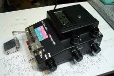
At rear, 3 positions toggle switch allow to change sampling rate or perform a DC calibration
(the ADC do not have HPF has many audio ADC have).

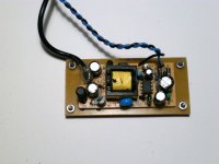
The EVM need also an external clock, that must be low noise and high frequency
to get maximum sampling rate and minimum jitter.
So,i add a 98.304MHz ultra low phase noise oscillator(Abracon ABLNO)
powered with low noise 3v3 regulator.

The original input front-end of the EVM is very simple, with only followers.
The ADC have differential inputs with Vref/2 offset, so the inputs must have this offset (not friendly).

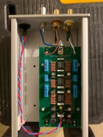
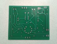
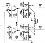
Because i want to use inputs in single-ended or differential mode, i designed another
front-end including a little low-pass filter to limit aliasing and out of band noise.

After some investigations and tests, I designed a front-end using the MAX44206
fully differential amplifier. The buffer has unity gain and allow 10Vpp full scale input (3.5Vrms).

After all of this done, i was very curious to know what we can really expect from this type of ADC...

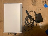
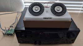
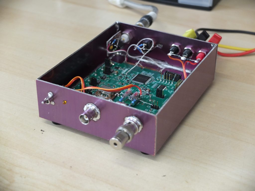
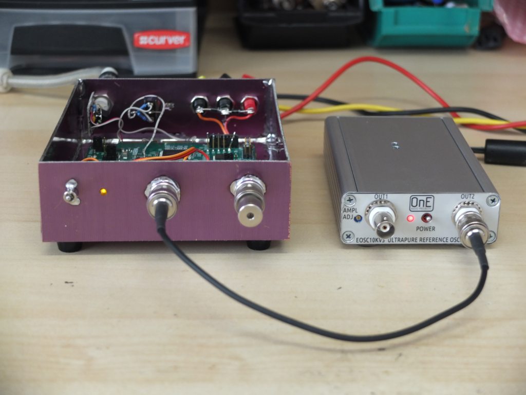
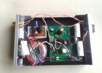
First , you will find below some pictures of the setups with the EVM becomed
an audio ADC.
Then, some measurements done today with it.

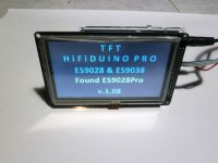
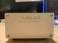
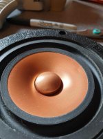
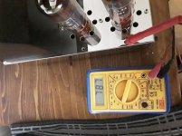
Front view with differential input and on/off switch
LTC2380-24_01.jpg


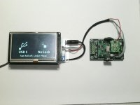
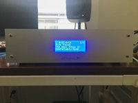
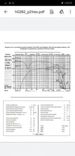
-1dB 10kHz THD test with EOSC10KV3 oscillator
LTC2380-24_06.jpg


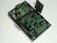
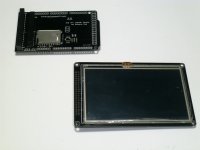
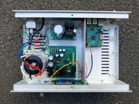
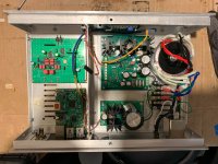
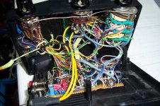
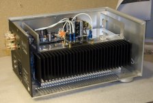
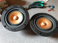
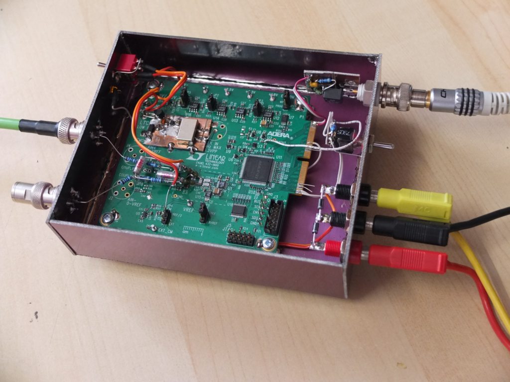
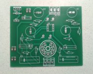
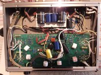
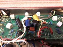
Top view, EVM PCB with oscillator and front-end buffer
LTC2380-24_05.jpg


Now, some measurements results.

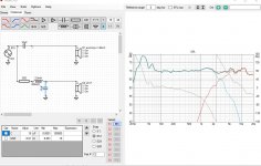
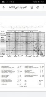
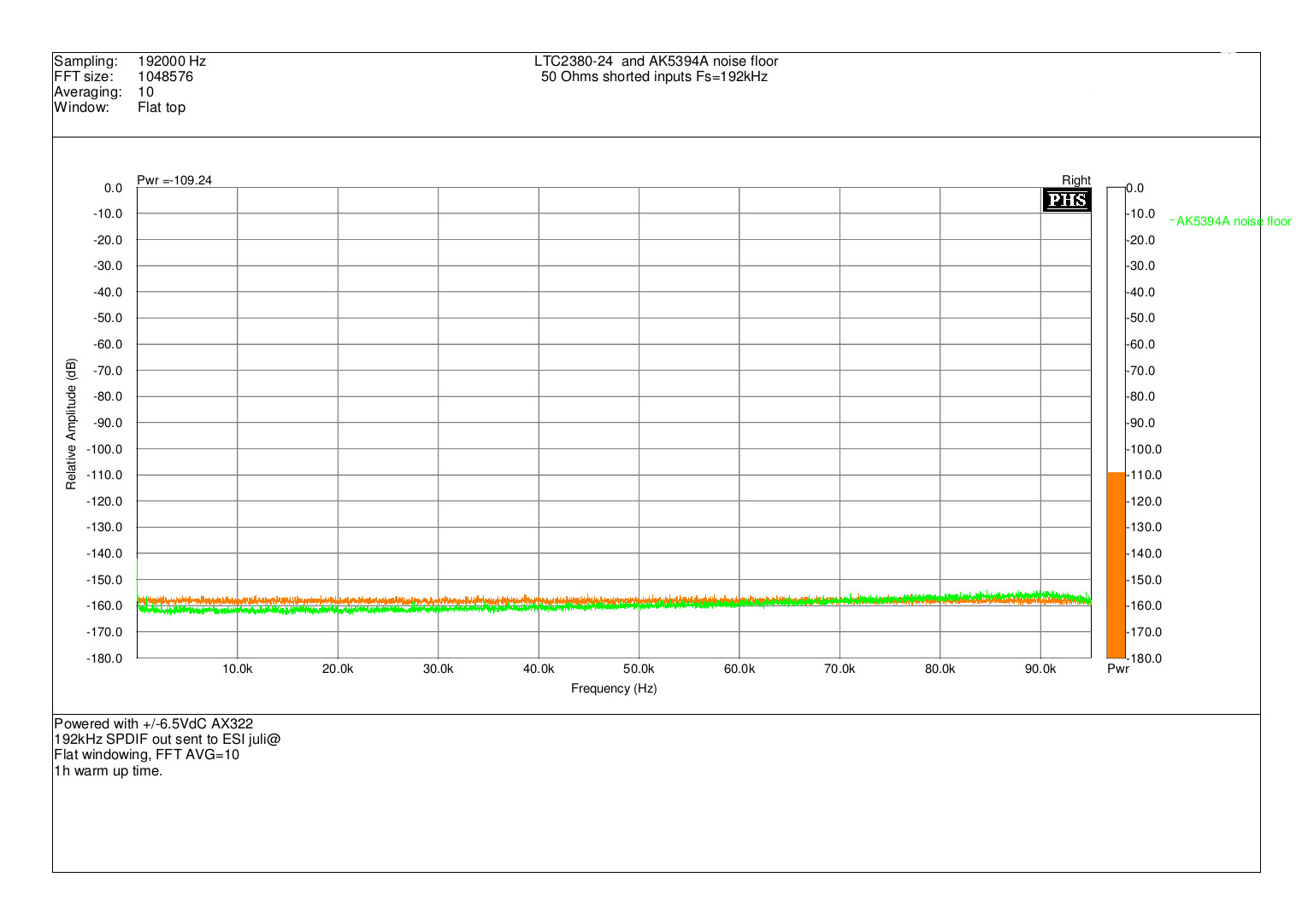
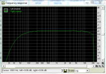
1/ 192kHz mode noise floor, 50 Ohms on each input (orange trace).
Green trace is the noise floor of AK5394A ADC to compare them.
LTC2380-24_AK5394A_noisefloor.jpg


We can see here that despite the lack of noise shaping and only
low oversampling ratio of LTC2380-24, the noise floor level is very near
what we get with AK5394A (-111dB).
The floor of LTC2380-24 is also extremely flat over bandwidth.

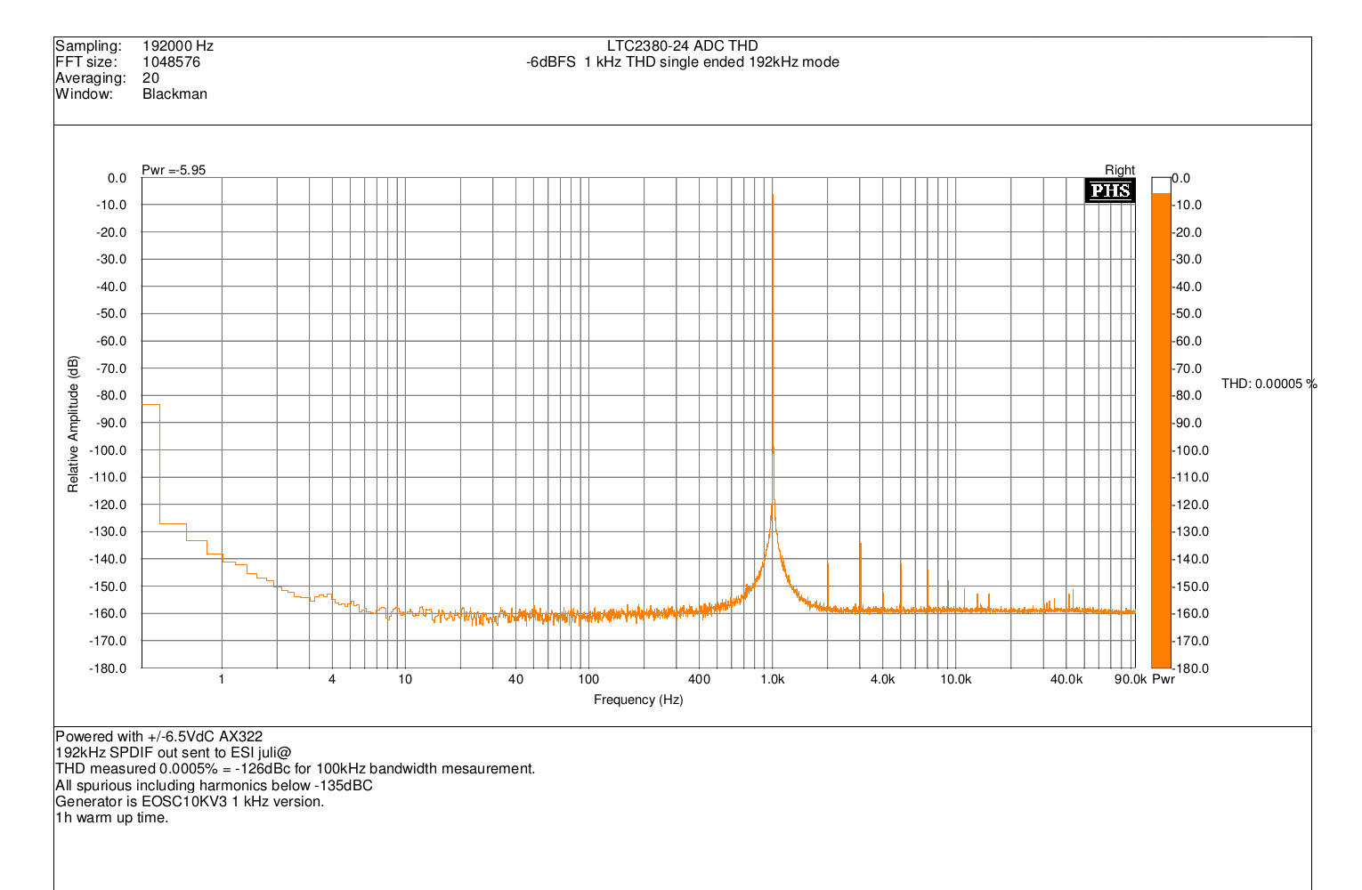
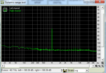
2/ 1kHz THD at -6dBFS 192kHz, single-ended.
Generator is EOSC10KV3 1kHz version, output level set to 3.15Vrms (8.9Vpp)
LTC2380-24_-6dBFS_1kHz_THD.jpg


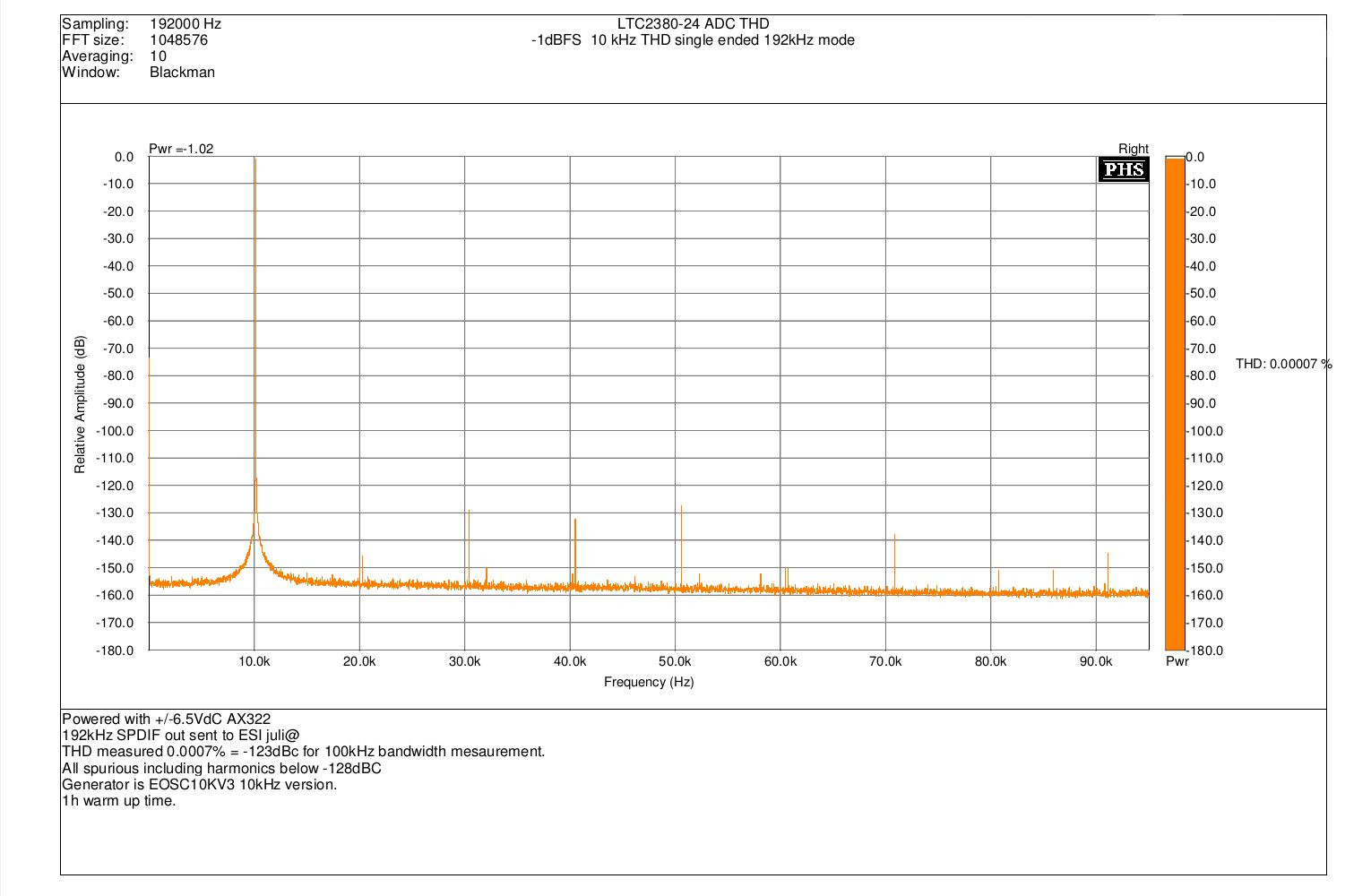
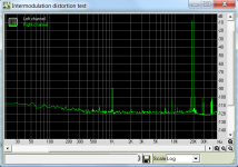
3/ 10kHz THD at -1dBFS 192kHZ, single-ended.
Generator is EOSC10KV3 10kHz version, output level set to 3.15Vrms (8.9Vpp)
LTC2380-24_-1dBFS_10kHz_THD.jpg


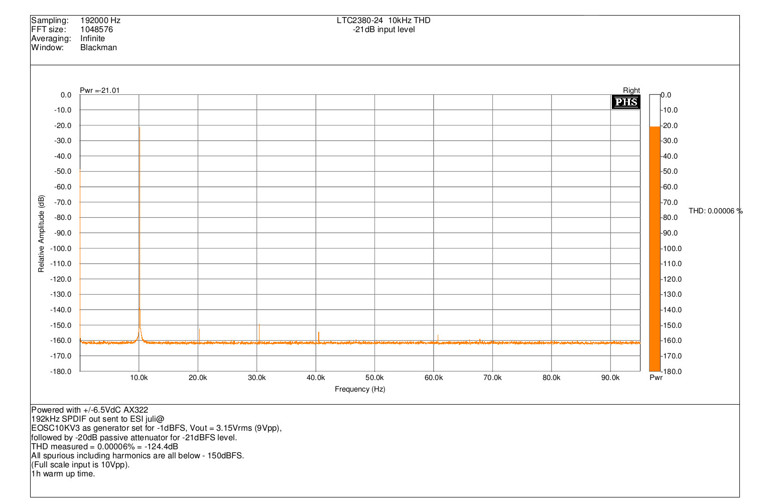
4/ 10kHz THD at -21dBFS 192kHZ, single-ended.
Same measurements as previously, but -20dB passive attenuator added
between generator and ADC input.
LTC2380-24_-21dBFS_10kHz_THD.jpg


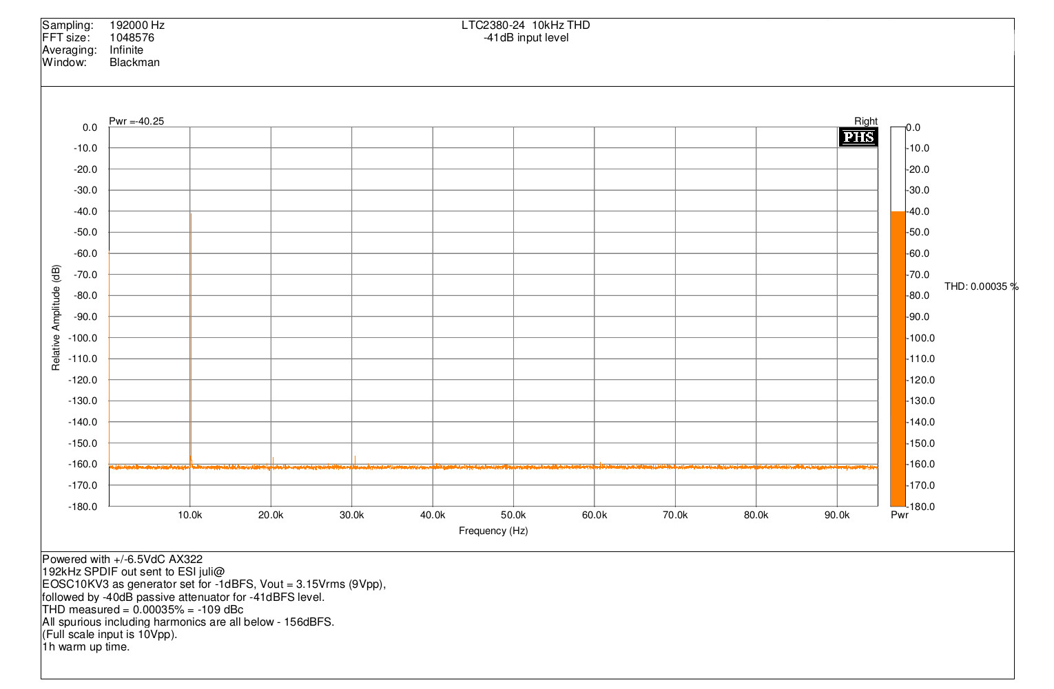
5/ 10kHz THD at -41dBFS 192kHZ, single-ended.
Same measurements as previously, but -40dB passive attenuator added
between generator and ADC input.
LTC2380-24_-41dBFS_10kHz_THD.jpg


As we can show, measurement results are very far to be ridiculous !
When can see exceptionally clean spectrum with THD level excellent at any levels,
even near to full scale. So, these results confirm me that modern SAR ADC IC
can be a very good choice to build a high performance audio ADC.
There is also many others advantages that is :
High DC accuracy (could be usable as high resolution voltmeter).
Easy to get 384,768 and event 1536 kHz sampling rate ! (if supported by sound-card).
DNR can reach 145dB using sample averaging (low rate).

I will continue to investigate in this direction, and i will also probably try the EVM
with the LTC2378-20 (pin compatible) that claim a better THD figure than the LTC2380-24...


Frex

Pure tube phono preamp kit

I'm looking to supplement my new build with a phono preamp as the next step, specifically for RIAA adjustments. I wouldn't mind building a kit, but so many of the ones I run into use op amps or mosfets in the signal line. Merlin sells a PCB on his site:

The Valve Wizard

Has anyone tried this or have any strong opinions about it?

I'm in the US if that makes a difference as far as sourcing.

FS A ton of random (nice quality) drivers for DIY

I am selling off my "stash." As requested by the mods, I have consolidated to one thread. I hope this is satisfactory. (For what it's worth, I am not a commercial business. Like most of you, I am just a hobbyist with an obsession and hoarding mentality. 😎 )

I also solemnly swear that I will not "bump" this thread, but I will update it periodically as new things are dug out of the speaker hoarding dungeon I call "my workshop." Every mad scientist needs a lab or a workshop.

Thank you all! I truly appreciate all of the folks who keep this buying and selling forum up and running, friendly, and productive.

Cheers!
baco99

Revisited YAHA amp

Hi all,
I have 3 pcb board left of a hybrid amplifier project, based on a revisitation I made from the YAHA headphone amplifier.
The main difference from it is that I preferred not to use the grid leak bias (tending to the positive region of Vg) but the classical cathode bias running tha amp at 24Vdc, through a simple LM7824 on B+ of the ECC82. The tube filaments too are fed with Vdc, from a CRC filter. The transformer is a toroidal one 12VAC and at least 20VA, I found this one doesn't offer magnetic coupling (and then zero hum) respect to a EI core transformer, that takes more space too. The PSU is made up of two units, one of which is double the other with a FW rectifier going to ECC82 plates.
A mention is deserved to the opamp, it should be able to bear >60/70mA of output current: so I deem the choice can be NJM4556, NJM4580 or NJM2114. The latter I have to say is very good (though with lesser current of the prevoius ones) but good soundstage and dynamics.
If someone's interested to the boards otherwise I appreciate some opinion about the circuit. As little implementation I also thought to use as alternative to Ra a CCS based on a constant current J-fet or LM334...I know it's a simple project, but for the overal cost of components is a fine sounding little amp.

Attachments

  • 20201020_144053.jpg
    20201020_144053.jpg
    632.5 KB · Views: 136
  • 20201020_144105.jpg
    20201020_144105.jpg
    519.8 KB · Views: 118
  • 20201019_180459.jpg
    20201019_180459.jpg
    558.1 KB · Views: 128
  • 20201019_180254.jpg
    20201019_180254.jpg
    819.2 KB · Views: 136

DSpeaker Dual Core 2.0 – Test Bench Report

This is PART 1 of my report (see other parts below).

I understand that this article may not be 100% fit for DIY Audio, but it is too technical for other forums like AVSForum, where I also a member. And I do compare commercial product with result of my DIY work. That is why I decided to publish my findings here.

Modern computing technology made significant progress in the last 15-20 years. It made cost of processing audio low enough, so it became common even in low cost devices. But most implementation are dedicated to multichannel audio for movies sound track, built into AVRs and surround processors. For some time there were efforts to expand digital audio processing to stereo systems designed to play music. But most hobbyists in hi-fi (or rather high-end) audio are very conservative in anything that is added to audio chain and violates rule “less is more” very popular among that crowd. But in recent years several vendors tried to convince owners of high quality music playing systems that they should add digital processing that compensates for speaker-room interaction and thus improve sound on top of passive room treatment. Thus we saw products from MiniDSP, DEQX and DSpeaker. I myself believed in having playback chain short (even as I do use and like Audyssey XT in my surround system ).

One of the main drawbacks of using signal processor is a fact that it has to be placed right before power amplifier and thus process analog rather than digital signal. As a result it adds additional A/D and D/A conversion, since all processing is done in digital domain. If music system uses only digital sources, this conversion can be avoided by placing digital processor before DAC (or using D/A convertor in it as DAC for the whole system). But with analog sources (vinyl media is still alive and kicking), this is not an option. As a result users have to trust that additional conversion stages do not alter sound to a degree when it can be heard. That is why ( despite actually working on device of that kind – see my report here http://www.diyaudio.com/forums/digital-line-level/282346-ultimate-behringer-mod-50-deq2496-1-a.html ) I didn’t try up to today any digital audio processing in my dedicated music system, using only passive room treatment to improve sound. But in my room I could go only so far.

And finally I decided to try one of digital processors which was for few years promoted in several magazines and web sites dedicated to high-end audio. Last trigger was a promotion letter that promised 40% discount on DSpeaker Anti-mode Dual Core. That device was called product of the year by Absolute Sound and received Class A recommendation from Stereophile (though neither published measurements confirming their rating). Considering offered discount, it was no brainer to place and order – I would not loose much if I do not like it and have to sell in near mint condition.

So I placed an order and soon box from California arrived at my door steps. My approach to anything new I get for audio is: put it on test bench before fist use. It allows me to avoid wasting my time on trying something that is broken (accidentally or by design). That was my approach to tube audio (you may find my reports about two tube amplifiers on that site http://www.diyaudio.com/forums/tubes-valves/208987-yaqin-mc-100b-powerful-advertised-value.html http://www.diyaudio.com/forums/tubes-valves/255409-lian-845-set-kit-commercial-product.html ) and I wanted to follow the same rule with my new digital processor – first confirm that it works as advertised. Thus this small black box went to my home lab for a proper testing.

Here are main parameters advertised by manufacturer:
[FONT=Arial, serif]
Interfaces:
[/FONT]
• [FONT=Arial, serif]2 x RCA inputs or alternatively 2 x XLR inputs[/FONT]
• [FONT=Arial, serif]2 x RCA outputs and 2 x XLR outputs[/FONT]
• [FONT=Arial, serif]Toslink S/PDIF digital input (2-channel PCM only, maximum rate 96 kHz)[/FONT]
• [FONT=Arial, serif]Toslink S/PDIF digital output (48 kHz)[/FONT]
• [FONT=Arial, serif]USB Audio (USB used also for measurement export and software update)[/FONT]

[FONT=Arial, serif]Analog Specifications:[/FONT]
• [FONT=Arial, serif]Dynamic Range: > 108dB[/FONT]
• [FONT=Arial, serif]Total Harmonic Distortion (analog in, analog out, typical): 0.003%[/FONT]

I planned to use it between my preamplifier and power amplifier, both of which have balanced interfaces, that matched well to DSpeaker offering balanced analog connections. Thus limitation of digital inputs in it was not an issue (and I do play high-resolution PCM and DSD content using my DAC).

As you can see dynamic range and distortion numbers are good enough on paper for practical use even with high quality systems like mine (Accuphase pre- and Bryston power amplifiers, B&W 802D speakers). But if DSpeaker lives up to specs – that is what I was planning to find.

For measurements in that case I use computer with RMAA Pro ( RightMark Audio Analyzer. Products. Audio Rightmark ) software tool that does measure main audio quality parameters and allows easy side by side comparison. My venerable EMU 0404USB is the A/D and D/A interface used along with it. This is not the latest signal processor, but it is well known to have exceptionally low noise and distortion which allows reasonably accurate measurements of most modern audio gear.

Thus I built a test system where I used balanced cables between EMU and DSpeaker units. I also used Toslink cables for SPDIF interface measurements (DSpeaker only has optical input and output). I did measurements with my laptop running from battery, but I didn’t notice any difference from using external power. Before measurements, I did factory reset of DSpeaker to make sure that there were no leftover configuration settings that affected the performance. Volume control and input trim settings in DSpeaker were set to 0 dB. In all measurements other than pure digital I used EMU in 24 bit and 96kHz sampling mode. In digital only measurement I had to use 24 bit 48 kHz sampling (see explanation below).

First test was for high level frequency response. And here is what I saw: Fig 1 (see attachments below).

Oops… I easily came to three conclusions:


  1. Low frequencies response is limited by -3.5 dB loss at 20Hz. This hardly can be called transparent when makers of DSpeaker declare one of their device uses as subwoofer equalizer. What kind of subwoofer they are talking here – one that comes with tiny satellites as HT-In-The-Box?
  2. Response in top three octaves has visible ripple. This usually points to poor implementation of reconstruction filter when there is not enough processing power for that.
  3. High frequencies are limited to just above 20 kHz with sharp rolloff above that point. This simply means that this DSpeaker is useless in a system where high-resolution content is played (this actually includes vinyl – it has some content in low ultrasonic range, and people value it for that). This means that if someone uses DSpeaker he will not have value from high resolution music sources. This also causes phase and timing smear associated with low sampling rate. Based on my measurements I concluded that it is likely that input audio sampling and internal processing is done at 48 kHz rate. Considering that digital processing was routinely done at 96 kHz rate even a decade ago, there is little excuse not to have it in device targeting high quality audio market.
Next test was to find out what is the real dynamic range of DSpeaker. In that test 1 kHz tone with level -60 dB is applied to the device input. Here is what I found at the output: Fig 2

As you can see output signal is reaching exactly -60 dB, which means that DSpeaker has a unity gain. But (Oops.. again) the noise floor is at -120 dB at middle and raises to -110 dB at low frequencies. Overall measured dynamic range according to RightMark tool is 88 dB which is way below advertised 108 dB. Of cause we do not know what adjustment curve was used by manufacturer to specify the value. RighMark tool does not use any correction (A, C etc.) and noise level is calculated over full frequency range. A can imagine that magic 108 dB number can be achieved when using A weighting. But from what we see it is clear that DSpeaker offers at best 16 bits of resolution, exactly what CD gives us – say bye-bye any advantage from high-resolution digital sources. Modern DACs offer from 18 (entry level), to 19-20 (mainstream), to 21 (state of the art) bits of resolution. Again there is no excuse not to have at least 18 effective bits of dynamic range in any modern device. Considering that when used in pure analog mode DSpeaker should never see 0 dB signal at its input (otherwise ADC will clip) practical dynamic range is even lower by at least one bit. Thus dynamic range of DSpeaker is LOWER that recording on CD.

Now let’s see how much of harmonic distortions DSpeaker adds to the signal. For that I used full range 1 kHz input signal: Fig 3

Here we see that harmonics are quite low, with third is the highest at – 97 dB. All other are below -100 dB and thus are not really an issue. Though you can see a lot of high frequency hash, even beyond 20 kHz pass band limit. Overall THD is 0.0028%, which is within manufacturer’s specification. But you can see that overall noise level raises few dB up from -120 baseline, which may point to rounding errors in processing.

Now let’s look at IMD. For that two tones (19 kHz and 20 kHz) at -7 dB level were sent to DSpeaker input: Fig 4.

Result is not bad at all (if ignore already known issue with limited dynamic range). 1 kHz difference tone is just above -90 dB. Third order IMD components and aliases at 30 and 40 kHz are all below -100 dB. Overall it results in IMD at 0.013%. This is not exceptional, but not bad either.

As a summary of DSpeaker performance in analog chain, I can say that it can be used only if the music source is CD and owner of the system does not try to squeeze last drop of sound quality. But would people like this even bother with adding another device to their music system?

(Story continues below...)

Attachments

  • Fig 1.png
    Fig 1.png
    45.7 KB · Views: 370
  • Fig 2.png
    Fig 2.png
    44.3 KB · Views: 358
  • Fig 3.png
    Fig 3.png
    40.6 KB · Views: 360
  • Fig 4.png
    Fig 4.png
    40.3 KB · Views: 360

Thinking to build a plug-in circuit

I’m interested to build a universal variable loudness to use with any amplifiers. The idea is to put it in between pre-out and main-in link of any integrated amplifiers. I had the schematics of Nakamichi 410 preamplifier as attached. Could anyone help to educate me whether I can build this circuit with or without any modifications, please? I'm not an electrical engineer but have some soldering skills. Thank you in advance

Attachments

  • 35863CC5-B3F9-4092-9BAA-6F9DD867AF71.jpeg
    35863CC5-B3F9-4092-9BAA-6F9DD867AF71.jpeg
    191.1 KB · Views: 169

Guyatone Flip 500

A friend brought this amp to me, saying that the amp is breaking up at low volume levels. With the master volume at 50%, he said he could only go up to 50% on the clean channel before break up. I cannot get the schematic or any technical info about this amp. I remember seeing somewhere on the net that this amp is rated 15watts with an 8in 8 ohms speaker. It has a single 12AX7 and 2 6L6GC tubes. The preamp is solid state. There is a pot on the amp for bias. Upon checking the bias, I get 39.44mA on one tube and 33.90mA on the other at 427V plate voltage. So one tube is dissipating16.84 watts and the other 14.48 watts, with a total of 31.32watts. This is double the rated power and can this be the reason for the early breakup. Is this bias setup safe and acceptable for this amp. Please assist.


Thanks

Yamaha EMX5000-20: Not sure what I did wrong..

I have a Yamaha EMX5000-20 powered mixing board that my band has used for several years for live gigs and practice both. This past year i have taken it upon myself to learn how to cean and maintain it, because it really is a nice unit. Well, a few of the knobs were scratchy, as well as some faders. After a good cleaning, the faders were still the same. So i read up, and watched videos on how to rejuvenate the faders and thought i would give it a try as music is something that will never be over for me.
So i got copies of the service and user manuals, and disassembled it as the service manual instructed. I desoldered the faders (ch17/18, and ch19/20 from the circuit board and cleaned them up as the videos instructed. I was also under the impression that the Aux Send jacks were not operational. So i also desoldered those, and 2 from ch 17/18, and swapped them with each other, soldering them back into place. All seemed to be ok, until i got it put back together, and now my right side main is not working. I did all of the elimination steps, and it is definitely in the mixer somewhere. Both speakers and cables work when hooked up to a different mixer. Also, the right side LED meter does not show any movement while the left does.
I am certainly capable of repairing it, i just need a little guidance on where to start. I checked over the inside of the mixer really well, and all my solder points and things i changed, and i just dont see anything that looks out of place, broken, fried, etc. All fuses appear to be intact as well. Thanks so much in advance for any help that anyone can provide.

Dyavox vr70 high bios voltage.

I'm new to DIY audio forum, so I hope I've posted my post in the right category. I have a lot of vintage hifi but no valve gear, so after reading how good valve amplifiers are, I decided to take the plunge and buy one. I bought a Dyavox VR70 of a famous auction site ( no names) big mistake!!
After receiving the amp I coupled it up to my mint warfedale e70s speakers and noticed the right channel was a lot lower than the left, I'm no electronic expert but had read how to bios the amp. I conected my Multimeter and set it to 2000m and connected to the valve bios test points and was shocked at the reading, 750m and counting down. The valves are a quad matched set and have a number in felt pen written on top of the el34 valves 305m. I've tried trimming the voltage down but the voltage is so unstable, I've given up. The voltage does come down after say a hour to around 150m. I removed the amp bottom cover to reveal the electronics, it's a real mess, a bodger has been inside and changed the circuit. Pictures enclosed. Sorry for the long posting.

Attachments

  • 20201019_102220.jpg
    20201019_102220.jpg
    896.7 KB · Views: 143
  • 20201018_104544.jpg
    20201018_104544.jpg
    803.1 KB · Views: 116
  • 20201018_104632.jpg
    20201018_104632.jpg
    684.7 KB · Views: 105

HH Scott 299C

My first tube amp and new to them and have a couple questions. HH Scott 299C and Klipsch Forte II speakers with Crites crossovers.
First, I see a high and low for magnetic cartridge for phono connection. I will be using a Shure V15 Type III and from what I researched is 3.5 ms and would be considered low after reading that 6ms is where one decides low or high.
Is that correct?

Secondly I read here that Scott amps are not compatible with modern tape decks. Modern being my question. The post stated that it was due to line input impedance not below 100k?

I have a Nakamichi 600 cassette tape deck and can not find any reference to "line input impedance" for it.
Compatible or is it not as the deck is circa 1975 so not too much modern for the 1961/64 ish 299C?
Thanks and anyone with Forte II and a 299C please chime in on how do you like?

Analogue active x-over delays

Can some help me here, in layman's terms!

I currently run my system controlled with a digital dsp enabling me to set delays for minimum phase/time alignment easily, with the help of arta.

Thought I would dabble with analogue again and purchased a Rane 23s. The manual has a chart for "rough" delay settings by crossover frequency and voice coil offset.

My question...why is the amount of delay required different at different frequencies for the same driver offset, which in my case is around 9" as I use a horn and cone mid set up..

Thanks.....
Projects by fanatics, for fanatics
Get answers and advice for everyone wanting to learn the art of audio.
Join the Community
507,787
Members
7,888,538
Messages

Filter

Forum Statistics

Threads
406,244
Messages
7,888,538
Members
507,787
Latest member
AlexMack