Hello all,
As many DIYers here and from my own experience in building ADC's,
we can seen that no obvious improvement was done from much years in ADC IC available.
The AK5394A designed 12 years ago still the better audio ADC available on the market.
I really think that the main reason come from the lack of market for a really better performance.
In all my investigations, i seen nowadays that SAR ADC market mainly used for instrumentation
have reached a performance level that become comparable to the better sigma/delta audio ADC.
LT has released some months ago a new SAR ADC, the LTC2380-24.
It is an high resolution 24bits 2Msps ADC that integrate a digital averaging filter to improve SNR.
After many hesitation, i had decided to purchase the evaluation board of this IC.
The eval board is intended to be connected to a DSP board (from LT also) for data collecting
to a PC and analysis with the LT software ( PScope).
I don't want to buy the DSP board because it's pretty expensive(300€) and my target
is to use the EVM with all my favourite audio software for sound-card.
The EVM board include an FPGA (EPM570) that is used to sent data to DSP board.
The ADC use a serial link (as SPI) to enable conversion and read serial data.
So, i wrote a complete new software in the FPGA to read the ADC at 1.536 MSPS,
and average 4,8,16 or 32 samples to give an output at standard audio rate of 384kHz, 192kHz, 96kHz and 48kHz.
Then, the data rate is transformed to fit in directly in SPDIF format,
so CPLD outputs drive a pulse transformer to get a coax SPDIF out.
At rear, 3 positions toggle switch allow to change sampling rate or perform a DC calibration
(the ADC do not have HPF has many audio ADC have).
The EVM need also an external clock, that must be low noise and high frequency
to get maximum sampling rate and minimum jitter.
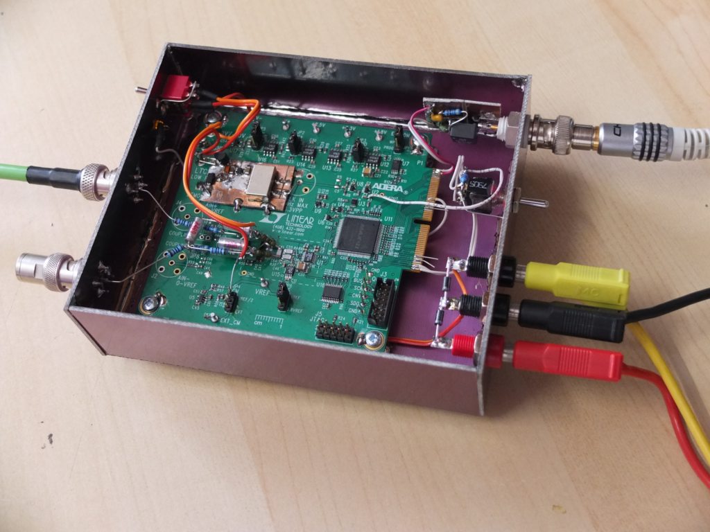
So,i add a 98.304MHz ultra low phase noise oscillator(Abracon ABLNO)
powered with low noise 3v3 regulator.
The original input front-end of the EVM is very simple, with only followers.
The ADC have differential inputs with Vref/2 offset, so the inputs must have this offset (not friendly).
Because i want to use inputs in single-ended or differential mode, i designed another
front-end including a little low-pass filter to limit aliasing and out of band noise.
After some investigations and tests, I designed a front-end using the MAX44206
fully differential amplifier. The buffer has unity gain and allow 10Vpp full scale input (3.5Vrms).
After all of this done, i was very curious to know what we can really expect from this type of ADC...
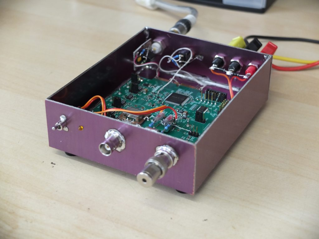
First , you will find below some pictures of the setups with the EVM becomed
an audio ADC.
Then, some measurements done today with it.
Front view with differential input and on/off switch
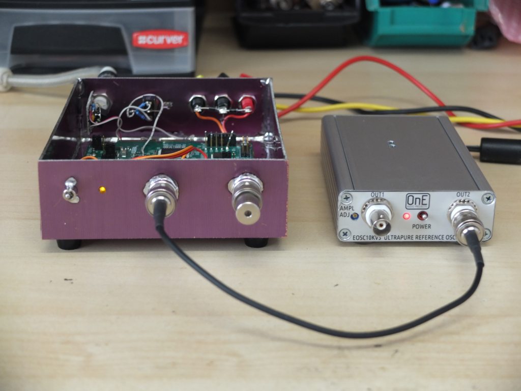
-1dB 10kHz THD test with EOSC10KV3 oscillator
Top view, EVM PCB with oscillator and front-end buffer
Now, some measurements results.
1/ 192kHz mode noise floor, 50 Ohms on each input (orange trace).
Green trace is the noise floor of AK5394A ADC to compare them.
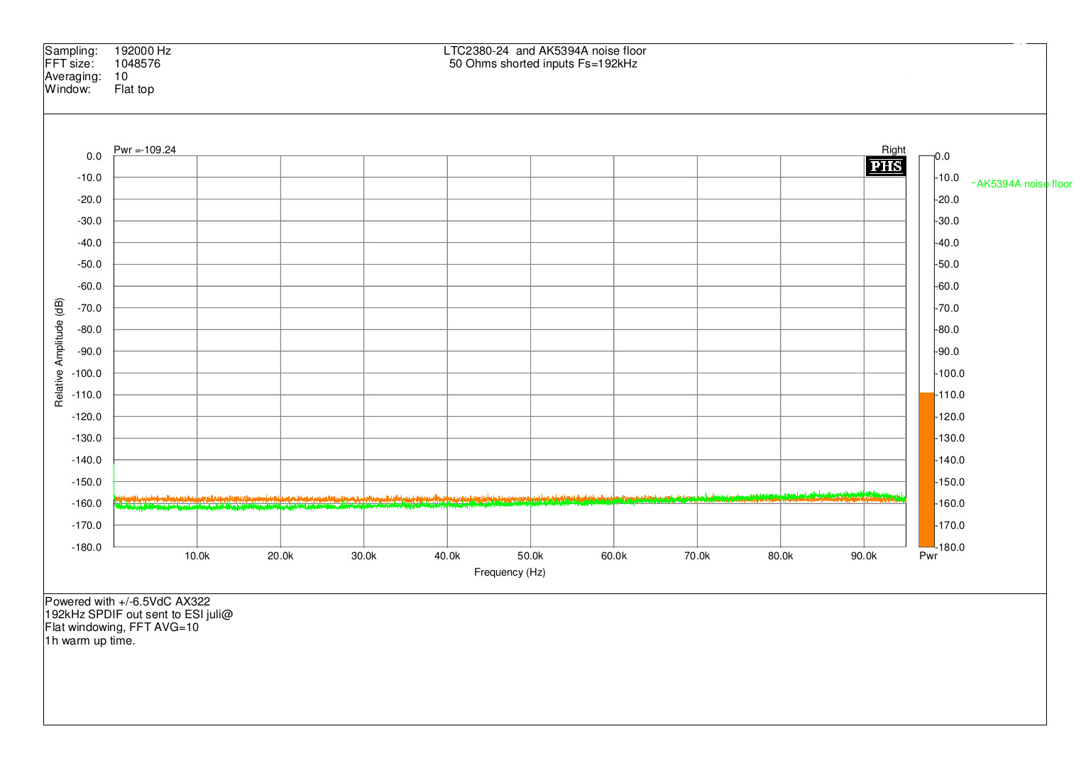
We can see here that despite the lack of noise shaping and only
low oversampling ratio of LTC2380-24, the noise floor level is very near
what we get with AK5394A (-111dB).
The floor of LTC2380-24 is also extremely flat over bandwidth.
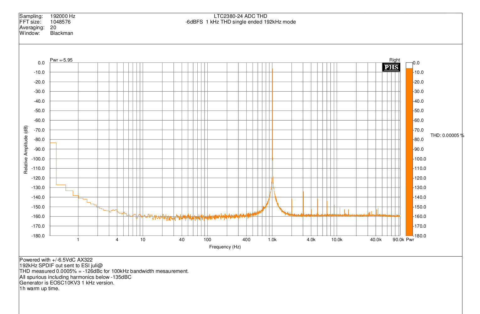
2/ 1kHz THD at -6dBFS 192kHz, single-ended.
Generator is EOSC10KV3 1kHz version, output level set to 3.15Vrms (8.9Vpp)
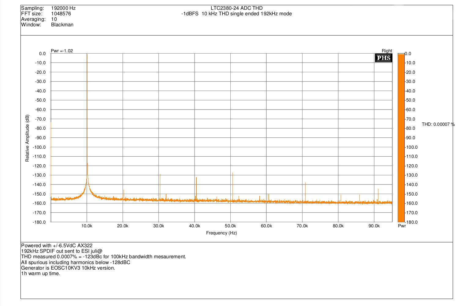
3/ 10kHz THD at -1dBFS 192kHZ, single-ended.
Generator is EOSC10KV3 10kHz version, output level set to 3.15Vrms (8.9Vpp)
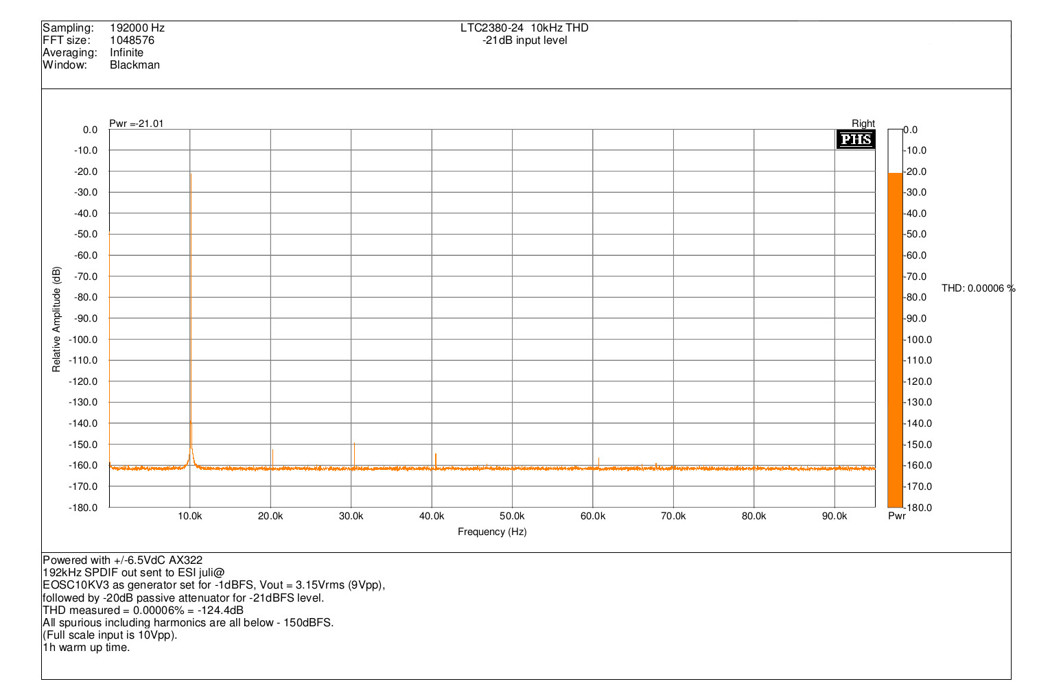
4/ 10kHz THD at -21dBFS 192kHZ, single-ended.
Same measurements as previously, but -20dB passive attenuator added
between generator and ADC input.
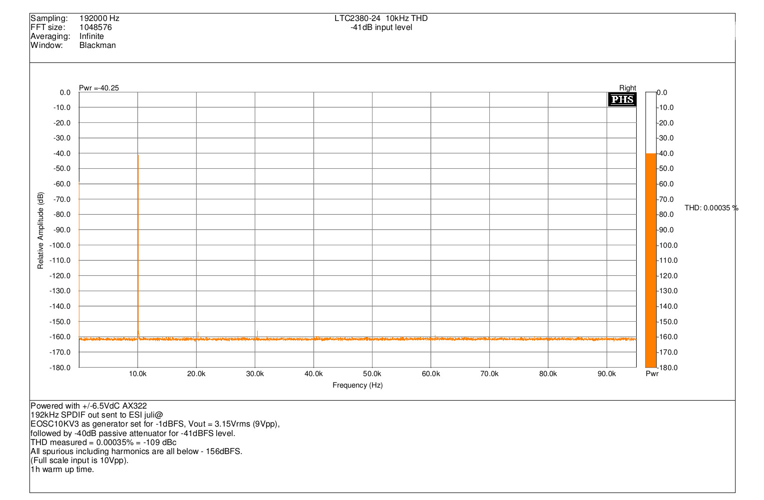
5/ 10kHz THD at -41dBFS 192kHZ, single-ended.
Same measurements as previously, but -40dB passive attenuator added
between generator and ADC input.
As we can show, measurement results are very far to be ridiculous !
When can see exceptionally clean spectrum with THD level excellent at any levels,
even near to full scale. So, these results confirm me that modern SAR ADC IC
can be a very good choice to build a high performance audio ADC.
There is also many others advantages that is :
High DC accuracy (could be usable as high resolution voltmeter).
Easy to get 384,768 and event 1536 kHz sampling rate ! (if supported by sound-card).
DNR can reach 145dB using sample averaging (low rate).
I will continue to investigate in this direction, and i will also probably try the EVM
with the LTC2378-20 (pin compatible) that claim a better THD figure than the LTC2380-24...
Frex
As many DIYers here and from my own experience in building ADC's,
we can seen that no obvious improvement was done from much years in ADC IC available.
The AK5394A designed 12 years ago still the better audio ADC available on the market.
I really think that the main reason come from the lack of market for a really better performance.
In all my investigations, i seen nowadays that SAR ADC market mainly used for instrumentation
have reached a performance level that become comparable to the better sigma/delta audio ADC.
LT has released some months ago a new SAR ADC, the LTC2380-24.
It is an high resolution 24bits 2Msps ADC that integrate a digital averaging filter to improve SNR.
After many hesitation, i had decided to purchase the evaluation board of this IC.
The eval board is intended to be connected to a DSP board (from LT also) for data collecting
to a PC and analysis with the LT software ( PScope).
I don't want to buy the DSP board because it's pretty expensive(300€) and my target
is to use the EVM with all my favourite audio software for sound-card.
The EVM board include an FPGA (EPM570) that is used to sent data to DSP board.
The ADC use a serial link (as SPI) to enable conversion and read serial data.
So, i wrote a complete new software in the FPGA to read the ADC at 1.536 MSPS,
and average 4,8,16 or 32 samples to give an output at standard audio rate of 384kHz, 192kHz, 96kHz and 48kHz.
Then, the data rate is transformed to fit in directly in SPDIF format,
so CPLD outputs drive a pulse transformer to get a coax SPDIF out.
At rear, 3 positions toggle switch allow to change sampling rate or perform a DC calibration
(the ADC do not have HPF has many audio ADC have).
The EVM need also an external clock, that must be low noise and high frequency
to get maximum sampling rate and minimum jitter.
So,i add a 98.304MHz ultra low phase noise oscillator(Abracon ABLNO)
powered with low noise 3v3 regulator.
The original input front-end of the EVM is very simple, with only followers.
The ADC have differential inputs with Vref/2 offset, so the inputs must have this offset (not friendly).
Because i want to use inputs in single-ended or differential mode, i designed another
front-end including a little low-pass filter to limit aliasing and out of band noise.
After some investigations and tests, I designed a front-end using the MAX44206
fully differential amplifier. The buffer has unity gain and allow 10Vpp full scale input (3.5Vrms).
After all of this done, i was very curious to know what we can really expect from this type of ADC...
First , you will find below some pictures of the setups with the EVM becomed
an audio ADC.
Then, some measurements done today with it.
Front view with differential input and on/off switch

-1dB 10kHz THD test with EOSC10KV3 oscillator

Top view, EVM PCB with oscillator and front-end buffer

Now, some measurements results.
1/ 192kHz mode noise floor, 50 Ohms on each input (orange trace).
Green trace is the noise floor of AK5394A ADC to compare them.

We can see here that despite the lack of noise shaping and only
low oversampling ratio of LTC2380-24, the noise floor level is very near
what we get with AK5394A (-111dB).
The floor of LTC2380-24 is also extremely flat over bandwidth.
2/ 1kHz THD at -6dBFS 192kHz, single-ended.
Generator is EOSC10KV3 1kHz version, output level set to 3.15Vrms (8.9Vpp)

3/ 10kHz THD at -1dBFS 192kHZ, single-ended.
Generator is EOSC10KV3 10kHz version, output level set to 3.15Vrms (8.9Vpp)

4/ 10kHz THD at -21dBFS 192kHZ, single-ended.
Same measurements as previously, but -20dB passive attenuator added
between generator and ADC input.

5/ 10kHz THD at -41dBFS 192kHZ, single-ended.
Same measurements as previously, but -40dB passive attenuator added
between generator and ADC input.

As we can show, measurement results are very far to be ridiculous !
When can see exceptionally clean spectrum with THD level excellent at any levels,
even near to full scale. So, these results confirm me that modern SAR ADC IC
can be a very good choice to build a high performance audio ADC.
There is also many others advantages that is :
High DC accuracy (could be usable as high resolution voltmeter).
Easy to get 384,768 and event 1536 kHz sampling rate ! (if supported by sound-card).
DNR can reach 145dB using sample averaging (low rate).
I will continue to investigate in this direction, and i will also probably try the EVM
with the LTC2378-20 (pin compatible) that claim a better THD figure than the LTC2380-24...
Frex
Hi Frex,
A very interesting project. And the performance seems to approach that of the AK5394A.
These new converters are definitely on my radar when looking for solutions capable of providing a good performance and sample rates above 192kHz. At the moment I am quite busy trying to finish my AK5394A based Analyzer, but after that I hope to get a chance of looking at the higher sample rates.
One of the challenges with the SAR converters is that they require a good external low pass filter.
How much filtering did you use?
Did you bypass the ADC driver on the board or did you build an amplifier in front of it?
Hi Frex,
Wow, this is a very interesting project. I am doing loudspeaker crossovers under Linux and have been looking for a 96kHZ or higher sample rate ACD to get the signal into the hardware so that I can process it. I can already get spdif into the computer, and this fills the missing link of analog --> SPDIF. The performance is certainly more than adequate!
Please keep working on this and post your progress!
A question if I may? Does averaging 10 times on the FFT not render the noise measurements incorrect?
Bingo,
may you consider to build a ADC module for Jens upcoming Analyzer, while his Analyzer is on a modular concept and may supporting higher sample rates 😀
Hp
may you consider to build a ADC module for Jens upcoming Analyzer, while his Analyzer is on a modular concept and may supporting higher sample rates 😀
Hp
Hi Frex,
A very interesting project. And the performance seems to approach that of the AK5394A.
These new converters are definitely on my radar when looking for solutions capable of providing a good performance and sample rates above 192kHz. At the moment I am quite busy trying to finish my AK5394A based Analyzer, but after that I hope to get a chance of looking at the higher sample rates.
One of the challenges with the SAR converters is that they require a good external low pass filter.
How much filtering did you use?
Did you bypass the ADC driver on the board or did you build an amplifier in front of it?
Hello JensH,
You are right, to avoid aliasing you need a good low pass filter.
Actually i use only 2nd order filter built with the fully differential input buffer (Fc=90kHz).
I work to improve that situation using high performance FIR filter using interpolation and decimation.
That allow to reduce drastically the input filter because of 8x oversampling ratio (1536kHz /192kHz).
This can be done in different ways, using the DIF1706 that make all the job but seem to be obsolete.
Another approach is to make on in CPLD. I work in these two ways.
ruairi,
I don't have already done IMD tests, but i will do that soon.
So, i have only 10kHz and 1kHz ultra-pure oscillators, so i will try with this mix.
And no, the FFT averaging doesn't change the effective physical noise floor.
Averaging allow to reduce random noise for harmonics and spurious extraction.
(SNR still unchanged).
With the ADC I also made new THD measurements of my EOSC10KV3 oscillators (from LT AN67) and my notch filter gain box set-up.
Results confirm well that all harmonics of the oscillator are below -140dBc (0.1 pmm).
Frex
Last edited:
I'm a little confused as to how the DF1706 would help? You need to decimate not interpolate since you are already oversampling, no?
As you mentioned, a filter in an FPGA or DSP would do the trick.
As you mentioned, a filter in an FPGA or DSP would do the trick.
Hello Chris,
The DF1706 only support audio sampling rate up to 192kHz.
To perform digital filtering, first it interpolate 8x (or 4x) to allow internal
RIF filter working with higher frequency.
Then, the RIF filter make it filtering, and for finish this high data rate is
8x (or 4x) decimate to recover original sampling rate.
This is an audio IC, it work as is because audio ADC/DAC doesn't provide
the high bitrate flux coming from their oversampler.
There is an advantage for me, because i provide to the DF1706 a 192kHz
rate that is already filtered by the 8x averaging filter of the LTC2380-24 ADC !
The RIF inside the DF1706 seem to be also very efficient.
It's clearly a much easy way to do the task (i think).
So, i work also on solution with CPLD, but would give me some job but
offer more flexibility .
Regards.
Frex
I could be wrong, but the DF1706 will only interpolate 4x for 192kHz input because you can't supply a system clock > 192fs at 192kHz.
I also don't see where it decimates the output? I thought this part was designed to interface with PCM1704, so it outputs 8x (or 4x) clock rates. PCM1704 accepts up to 25MHz bit clock (96kHz * 8 * 32b = 24.576MHz).
It seems like you will get WCK and BCK out at the oversampled rate unless I missed something in the datasheet. I don't think this part works like an ASRC which can output the same rate in and out.
Of course, it will certainly work as a filter.
Hello again Chris,
Yes, i read the datasheet a little bit to fast.
The output is at 8x (or 4x at 192k) the input sampling frequency.
It is not a big problem, decimate by 4 or 8 is very easy to do.
And yes, at 192kHz the oversampling ratio is only 4.
So, my only worry is how the FIR perform at this sampling rate...
(nothing said in datasheet).
Otherwise, i already wrote the code to output I2S on the CPLD.
Frex
You have done some impressive work on this. I'm not sure what your goals are but if you feel so inclined I think open sourcing the code (to get others to contribute) would be really great. However keeping it under wraps is valid as well.
That ADC is designed for undersampling I believe and can work with input up to 100 MHz? You definitely need a low pass filter at the input but with some magic you may be able to look well above the audio band.
That ADC is designed for undersampling I believe and can work with input up to 100 MHz? You definitely need a low pass filter at the input but with some magic you may be able to look well above the audio band.
You have done some impressive work on this. I'm not sure what your goals are but if you feel so inclined I think open sourcing the code (to get others to contribute) would be really great. However keeping it under wraps is valid as well.
Need a larger FPGA first, no space for filters in the EPM570....
That ADC is designed for undersampling I believe and can work with input up to 100 MHz? You definitely need a low pass filter at the input but with some magic you may be able to look well above the audio band.
Actually it's spec'ed at 34 Mhz, but if you want to keep it accurate it require 6.8 nF capacitors on the inputs, can't see how to drive those at high frequencies....
Hello,
Thank you Demian.
The CPLD code is not secret and i done it with help of many sources available online.
The CPLD do much job, send directly SPDIF output and also I2S fine today.
As said Soren, the CPLD is too small for a good FIR filter (with at least 64 taps) this
is because i would like to try using external one, the DF1706 that can do the (good)
job easily using I2S in and out to the CPLD.
I plan also to add a bigger CPLD, probably a MAX10 . I installed Quartus Prime
(the latest) that is compatible with MAX10, but IP core for RIF filter design seem
to be unavailable and a license need to be purchased...not cool.
My goal would be mainly to make a design that is seen as an external sound card,
with better specifications as possible. The main reason it is because many
FFT software are available with that. (Not to to make an under-sampling receiver).
Using the LT demo-board with only some tweak prove that SAR IC have reach now
same or better THD level than any Sigma-Delta ADC because of lack of development
of this component this last 10 years (or because some limits has been reached ?..).
I know that input filtering is required, from now the second order LPF at input doesn't
stop aliasing above FS/2. So as you said, with the input bandwidth of the ADC and it's
2MSPS sampling rate it is possible to make a very good spectrum analyser
with a bandwidth much wider than the audio band.
Frex
Its interesting that the AK5394A is so old and represents such an achievement. The market for high performance audio ADC's has been flat for years but it seems to be heating up again. A new ESS ADC is supposed to be good (the existing one is not) and AKM has several in process. The AK4397 was focused on extended bandwidth and seems to have traded THD for bandwidth.
Here is a plot I made of a fully tweaked AK5394A demo board shoing what can be had under ideal circumstances. I can't be sure I could duplicate this measurement now.
With an SAR ADC a lot of interesting things can be done other than a straight FFT.
Here is a plot I made of a fully tweaked AK5394A demo board shoing what can be had under ideal circumstances. I can't be sure I could duplicate this measurement now.
With an SAR ADC a lot of interesting things can be done other than a straight FFT.
Attachments
High DC accuracy (could be usable as high resolution voltmeter).
Easy to get 384,768 and event 1536 kHz sampling rate ! (if supported by sound-card).
Frex
Well, SPDIF has it's limits at 192khz or an using 2x speed to get 384khz
Its interesting that the AK5394A is so old and represents such an achievement. The market for high performance audio ADC's has been flat for years but it seems to be heating up again.
May look at the performance on a prototype with the new AK55.. chip
http://www.diyaudio.com/forums/equipment-tools/282381-usb-sound-card-audio-spectrum-analysis-18.html#post4692165
A new ESS ADC is supposed to be good (the existing one is not) and AKM has several in process.
The beef question on this: Why they deal so long ...
With an SAR ADC a lot of interesting things can be done other than a straight FFT.
To get on the root of this higher sample rates & real time processing some tweaks/work has to be done. On the interface (xSpeed) & application (multi threading) & protocol = ASIO (MS is currently dead end on 384kHz.
Otherwise a store and forward is required to deal with this higg sample rates: This means a sample FIFO and a transfer bus & API is required.
Hp
Hello,
Thank you Demian.
The CPLD code is not secret and i done it with help of many sources available online.
The CPLD do much job, send directly SPDIF output and also I2S fine today.
As said Soren, the CPLD is too small for a good FIR filter (with at least 64 taps) this
is because i would like to try using external one, the DF1706 that can do the (good)
job easily using I2S in and out to the CPLD.
I plan also to add a bigger CPLD, probably a MAX10 . I installed Quartus Prime
(the latest) that is compatible with MAX10, but IP core for RIF filter design seem
to be unavailable and a license need to be purchased...not cool.
My goal would be mainly to make a design that is seen as an external sound card,
with better specifications as possible. The main reason it is because many
FFT software are available with that. (Not to to make an under-sampling receiver).
Using the LT demo-board with only some tweak prove that SAR IC have reach now
same or better THD level than any Sigma-Delta ADC because of lack of development
of this component this last 10 years (or because some limits has been reached ?..).
I know that input filtering is required, from now the second order LPF at input doesn't
stop aliasing above FS/2. So as you said, with the input bandwidth of the ADC and it's
2MSPS sampling rate it is possible to make a very good spectrum analyser
with a bandwidth much wider than the audio band.
Frex
I have a ESS ADC project going which isn't progressing that great and 1audios comment on the current ESS ADC, which I don't question, make me even more interested about this effort. Are you planning to make something available to the community? I would be interested in this. My aim is 2 mic stereo recordings.
//
Hi Frex and all,
I've kindly been guided to this thread which I find to be very interesting indeed 🙂
As it is I'm also designing an ADC based on the LTC2380-24 and since I'd like to use its full sampling rate (1.536 MHz is likely to work according to LT) I recently started this thread to find a solution to transferring the data from some ADC channels into the PC without drop-outs etc.:
http://www.diyaudio.com/forums/pc-based/292388-seek-programming-assistance-paid.html
Just in case it is of interest to others as well (and please feel welcome to suggest solutions if you have some ideas).
Cheers,
Jesper
- Home
- Design & Build
- Equipment & Tools
- SAR ADC for high performance audio ADC project [LTC2380-24]
