Cathode and other types of feedback

I was rereading Morgan Jones' book (hoping that some more would sink in) and I came across a section on feedback. Just want to make sure I've got the basic ideas right...

Cathode feedback is best used from dedicated taps built into the transformer. These are different from an "Ultralinear" connection in that you can use whatever voltage you want instead of applying the entire B+, right?

If you don't have the dedicated taps on the transformer, you can achieve a type of cathode feedback from one of the secondary taps. Do you have to have an unused tap (i.e. an extra 8 ohm tap when you have the speakers hooked to the 4 ohm) or can you source feedback from the same tap you have hooked to the speakers?

Jones mentioned in passing what he thought should be the optimal configuration, feedback from the speaker terminals. This makes the most sense to me too but I must be missing something since I have never heard of anyone actually using this technique. What would be involved in using feedback from the speakers around the output stage of an amp? I suppose taking feedback from the speakers and applying it to the input would be the very definition of a global feedback chain🙂 I tend to shy away from global feedback because of stability issues, I assume that it would be even more tricky if the feedback was sourced from the very end of the chain, am I right?

Thanks for any info you can send my way, still scratching my head over how some of these things work, I'm hoping to start on my first amp before too long...

Isaac
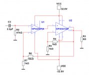
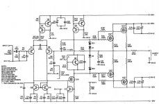
OPA541 improved with OPA452

The OPA541 is a powerful chip.
Package is 11-pin TO-220.
When used with only a few parts it can output 9-10A and dissipate 125 Watt.
Power supply can be up to +/- 40 Volt.
The THD is low but not the best.

To perform with lower THD we can use a driver chip.
This will control the OPA541.
We need an op amp with max power supply +/- 40 Volt.
This is where OPA452 comes in.
Package is 7-pin TO-220 or DDPAK/TO-263.
OPA452 is unity gain stable.

The power supply is 2x24VAC.
I recommend one 300VA transformer.

Result is 48 Watt output in 8 Ohm.
With very low distortion.

Attachments

  • OPA452-OPA541_publish.jpg
    OPA452-OPA541_publish.jpg
    55 KB · Views: 1,022

Advice on possible crossover?

Thinking of cobbling together MarkAudio Pluvia 11 (7.1ohm) with a Tannoy 8" Bass woofers (4.5ohm) beneath.
The more I read on crossover design the less certain I become about how to proceed.
The bass woofers were crossed at 400hz in the 611mk2 so planned to build xover at this frequency.
Tried plenty calculators but much advice says that experimentation is more useful than the calcs.

Aside from binning the project, what would you do?

MQ & Lundahl Iron, Khozmo Attenuator, Tubes

Hi all -

I took apart some of my stuff and have fs items as a result. Yes it was painful to tear them down, but it felt like the time :

Iron :
Lundahl LL1673 pair - $150 -- sold
Magnequest EXO-03 pair - $200 -- sold
Magnequest TFA-2004 Jr Nickel. 3k pri. - pair $350 -- sold
Magnequest BCP-15 pair (40h/50ma )- $100 (one of these is a little marred on the brass, but that obviously doesn't impact its performance. I always had these chokes under the hood anyway, but just pointing it out) -- sold
Magnequest B7-15k Ni pair - $140 -- sold
Stancor P-6315 - $50 -- sold
Hammond 374BX - $80 -- sold

Attenuator :
Khozmo 100k Mono MkII, Shunt - Pair of monos - $150. Loved 'em. -- sold

Tubes :
Shuguang 2a3c - $65/pair -- pending sale
ValveArt 2a3 - $50/pair
Westinghouse 2a3 - $40/pair - I barely tried them out in the amp and they work, but since I can't further test them and I don't know their hours, I'll let these go for low $ -- pending sale
Svetlana EL34 matched quad - $60/quad
SED EL34 single - $20
GE 5670 5-star - $20/pair
RCA 5u4g - $15
Tungsol 5u4g - $10
Sovtek 5ar4 - I have 2, $5/per -- pending sale
Pinnacle 6j5GT - I have 4, $8/per

maybe someday I'll dig into the mass of 9-pins I have but now is not the time. I have a ton of 12au7, 12at7, some 6n1p, 5687, 6n6p -- 4x 6n6p pending sale. If you want to ask about something I might be able to look.

On top, I'm likely using a flat rate box at $8 to ship whatever wherever in the US. Sorry I really don't want to get into international shipping with this post, but I could be convinced otherwise.

If you want to PM me with a bundle offer that's fine. I'm posting a separate fs ad with a bunch of capacitors as well. Check it out.

I only took one photo just to show the iron and attenuators in group. If anyone wants to see other individual ones let me know.

Have a great day !
-Steve

Attachments

  • IMG_0018.jpg
    IMG_0018.jpg
    446.8 KB · Views: 769

Linkwitz Inspired

Over the last almost decade I have built numerous clones and variations of the Linkwitz Pluto and LX Mini. While I appreciate the holographic imaging design approach and results I’ve never been that happy with these designs sonically. It’s something to do with the smoothness of the top end. I struggle w ssssssssy vocals and a lack of midrange clarity, punch, impact (however it can be described) - regardless of the exact configuration my attempts at using a full range driver for the top end are unsatisfying. This is especially obvious when compared side by side with other references. However I seem to be stuck on tubes and digital XO. I’d like to get this top end issue put to rest. Any ideas or shared experience out there? I spent a lot of time trying to eq this lasted design - for only a mild improvement and now a certainty that I can’t get what I’m looking for 🙂

Attachments

  • 3AD3336E-34E7-4AC4-9FC2-FB0765EFC5E3.jpeg
    3AD3336E-34E7-4AC4-9FC2-FB0765EFC5E3.jpeg
    448.4 KB · Views: 429
  • 082036A2-6BDD-4CD6-AAFD-D8C4A18A6AE9.jpg
    082036A2-6BDD-4CD6-AAFD-D8C4A18A6AE9.jpg
    956.7 KB · Views: 433

SYMASYM TO3

Hallo There
I have 2 of these set!
I want to offer you SYMASYM To3 from Rudi
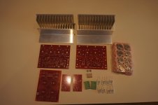
The offered set / kit consists of:

- 2 x TO3-SYMASYM PCBs
- 1 x DX PSU PCB
- 2 x Speaker Protection PCBs
- 2 pairs of well matched MJ21195- and 2 pairs of well matched MJ21196- output transistors
- 2 heatsinks 165 x 80 x 35mm
- 2 ALU L profiles 50x50x5mm, 140mm long
- 2 ERO/Roederstein MKT1822 /10µF and 2 Vishay MKP1837/10nF input, DC-blocking capacitors

The price for one set / kit is 95;shipping costs within Europe is included.


All components are absolutely new and have never been used before.
Send me a PM, if you want to have the set / kit.

Best regards - abc4230

Attachments

  • DSC08609.jpg
    DSC08609.jpg
    583.3 KB · Views: 421
  • DSC08611.jpg
    DSC08611.jpg
    680 KB · Views: 413

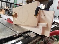
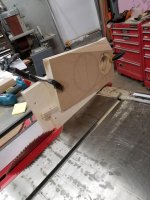
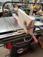
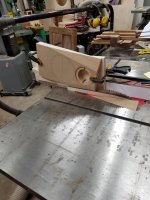
My jig/method for making bevelled/chamfered baffles...

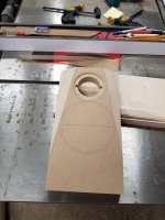
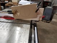
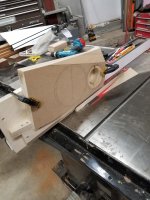
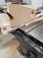
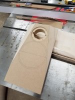
Cut a wedge so the bevel line is parallel to the horizontal plane and attach a small stop block so the baffle does not want to ride backwards during the cut.

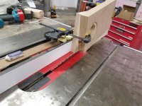
Attach wedge to a ply carrier board and make the cut.

Remove and flip wedge, cut other side.

Attachments

  • 78977045_10156902736382741_4054949005782679552_n.jpg
    78977045_10156902736382741_4054949005782679552_n.jpg
    63 KB · Views: 363
  • 79471108_10156902736412741_6492856242099191808_n.jpg
    79471108_10156902736412741_6492856242099191808_n.jpg
    61.7 KB · Views: 360
  • 76765571_10156902736447741_4683298645263515648_n.jpg
    76765571_10156902736447741_4683298645263515648_n.jpg
    73.9 KB · Views: 372
  • 78579105_10156902736502741_7282857004513624064_n.jpg
    78579105_10156902736502741_7282857004513624064_n.jpg
    66.4 KB · Views: 359
  • 78931204_10156902736547741_5100627758283751424_n.jpg
    78931204_10156902736547741_5100627758283751424_n.jpg
    71.2 KB · Views: 366
  • 79137274_10156902736587741_452774262638379008_n.jpg
    79137274_10156902736587741_452774262638379008_n.jpg
    81.9 KB · Views: 244
  • 78965114_10156902736647741_8444502901958639616_n.jpg
    78965114_10156902736647741_8444502901958639616_n.jpg
    69.4 KB · Views: 242
  • 78759232_10156902736702741_5694368250645708800_n.jpg
    78759232_10156902736702741_5694368250645708800_n.jpg
    76.5 KB · Views: 219
  • 79628137_10156902736787741_3529851294925717504_n.jpg
    79628137_10156902736787741_3529851294925717504_n.jpg
    67.4 KB · Views: 217
  • 79122679_10156902736842741_985377106722553856_n.jpg
    79122679_10156902736842741_985377106722553856_n.jpg
    62.4 KB · Views: 228

Is this a good UcD400HG and driver match?

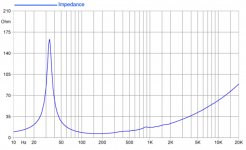
I have Hypex UcD400HG amps driving my midbass in an active system. Recently I'm venturing into open baffle and I'm considering Faital Pro 18HP1010 (8 ohm) in OB to run from 50 to about 400Hz, and I'm wondering if they are a good fit because of the driver impedance at 50Hz.

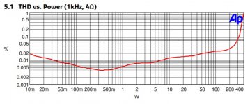
UcD400HG is rated at 400W into 4 ohm, which means THD under 1%, yet THD jumps from about 0.05% starting at about 200W, or 50% of rated power.
UcD400HG THD.jpg
The amp is also rated at 240W into 8 ohm. Extrapolating from the 4 ohm info, I’m estimating it must deliver about 120W at 0.05% THD. Further extrapolation into 16 ohm I guesstimate about 145W rated power and hence about 70W at 0.05% THD.

Faital has a 4 ohm version of the 18HP1010, but it is not available here. Only the 8 ohm version:
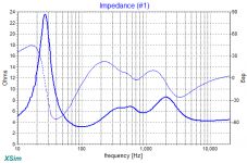
Faital 18HP1010 impedance.jpg
At 50Hz the impedance is about 20 to 25 ohm.

FWIW, I have subs below 50Hz, and a 5m x 10m living room where normal listening is at about 90dB SPL.

Seems to me the high impedance at low frequencies might deplete the amp capabilities but maybe I’m just getting tangled in numbers and your experience shows it would work well.

Thoughts?

macbook pro inverted phase?

Hi
I connect Line-out to the Line-in with same 3.5mm stereo cable.
And get different results in phase and transfer measurements.
I used fuzzmeasure pro V333
And REW
.
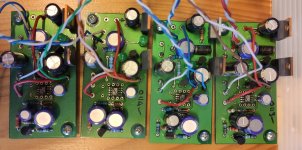
Some apple lap top models showing inverted phase.
Step response on some laptop-s 2 model of MBP 17in showing opposite phase at input OR output by going first into negative region on Y axis
.
Mac mini have correct phase and step response. (High siera.)
15in MBP old model correct phase and step response. (Mavericks)
17in MBP old model opposite phase 180deg. (Mountain Lion)
17in MBP old model opposite phase 180deg. (Mavericks)
.
I am sure that we have more mac users. Please give some comments and personal experience on this issues?
.
Thanks 🙂

Can i use 2x mono ICEpower 500ASP as 1 bridged 1000w+ amp?

Hi,

Sorry my ignorance and lack of technical grasp.

I have 2 mono ICEpower500ASP amplifiers, and I have DSP capabilities (to flip signal's phase I presume).

So... is it possible to use these 2x mono amps into one 1000w+ mono?

I would feed one mono 0º signal to one amp, and one mono 180º signal to the other amp. Subwoofer would be connected:

+ to 0º amp (positive terminal)
- to 180º amp (positive terminal)

Looking forward to your replies!

Cheers

passlabs x1000

hi im new to this site
i have the chance to buy some last run passlabs x1000

can someone please tell me the main differences between these and the x1000.5
also can i have some opinions on these monos
i would be running these through a set of focal grande utopia be
lastly any indication on 2nd hand price would be great etc

thanks in advance🙂

Please review my design?

I've been working on a design, and hope someone is willing to review it before I start ordering parts. There's a decent chance I got it wrong somewhere.

Design goals:
- Reasonably flat response
- Good low-end extension
- Within a modest budget

The last goal is because I know I'm still a novice at this. At this stage it would most likely be a waste to spend lots on premium drivers and crossover components.

For this project I'm thinking about creating a 3-way floorstander.

First I selected the drivers I want to use. For the bass I opted for the Dayton SD215A-88. A budget-friendly driver that doesn't need much volume in a BR enclosure. For mids I went with the Dayton RS125-8. I've used this driver before, and it sounds really nice to me. For the highs I choose for the Vifa/Peerless XT25BG60. It has a smooth FR and is acclaimed for it's price/performance. One driver of each per speaker (TMW). Any comments on these choices?

I calculated the volume needed for the bass driver using WinISD. I went with the default QB3 alignment, as the required volume works perfecty for me (though the BB4 and C4 alignments were not much different).

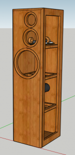
Next I designed a cabinet using Sketchup. I took the woofer magnet, bracing and BR volume into account to calculate the required woofer compartment (separated from the mid and tweeter).

Then I used VitiuxCad2 to trace the response graph of the Peerless tweeter and generate FRD and ZMA files (Dayton provides these files). I also used the 'Diffraction' tool to draw the baffle shape. For each driver I played with placement and generated an FRD file in which diffraction and baffle step are taken into account.

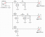
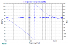
These ZMA and 'baffle compensated' FRD files were imported into XSim to design a crossover. I started off by following the instructions in the 'Introduction to designing crossovers without measurement' thread to calculate an LR2 network on each channel. Next I added L-pads to attenuate both the mid and the tweeter. To my surprise, things were looking quite promising at this point. I went on to tweak the values of components until I managed to get the FR graph within +/- 1dB between 100Hz and 20kHz. Next I made a shopping list of components, and adjusted values of the components in XSim to reflect those in the shopping list (like DCR for inductors and non-E12 values). The effect on the FR plot was very minimal. For cost and DCR reasons I went with an iron-cored inductor on the bass network. Would that be advisable in this situation? The crossover points are around 650Hz and 2900Hz.

At this point I could just go ahead with it and order all the parts. But I wonder if it would be better to just order the drivers first, build the cabinet, and measure the response of each driver unfiltered. Using the acquired data I could tweak the crossover further (or even start from scratch). But would this be worth it? Would you expect a lot of difference between real-world performance vs. simulations?

If measurement-based filter design would be recommended... I do have a Dayton iMM-6, an entry-level measurement mic. Don't know if it's fit for this purpose. Maybe I should invest in a UMIK-1? Or maybe even a Behringer ECM8000?

As mentioned earlier, it would be very much appreciated if a more experienced builder could review my design. I understand I'm asking a lot of questions.
I've learned most of what I know about designing and building speakers on the diyaudio.com forum. Youtube channels like 'Impulse Audio' and sites like audiojudgement.com also taught me a lot. But the more I learn about this stuff, the more I understand how much more there is to learn.

Attachments

  • Sketchup.PNG
    Sketchup.PNG
    197.2 KB · Views: 506
  • XSim XO.PNG
    XSim XO.PNG
    115.7 KB · Views: 512
  • XSim FR.PNG
    XSim FR.PNG
    42 KB · Views: 497
  • XSim Z.PNG
    XSim Z.PNG
    48.1 KB · Views: 503

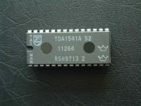
groups buy TDA1541AS2 chips, money back gurantee

hi ,

As member flyboi advise, why not try to put this chip for groups buy because we need to accumulate more single order for bulk order's price. Because bulk order we can lower the chips prie to IC's dealer.

Pls don't pay money, only reg.in here to group the total name list that had interest for this chip. If at last cannot arrived the bulk order. May be will cancel for this groups buy.


TDA1541AS2 groups buy.


Pls check the photo for the sepc of different grade of TDA1541a chips, 1545 & 1543 also contain too.

Since 9713 date code was almost the best of the TDA1541AS2 because this date code was under japan manantz & zandan lab standard & request for them to further selection.

At last we agree the total pcs if reach 50pcs will had max 7% discount.

If reach 100pcs will had 10% discount, sorry no more. This is the best that I can do. I will share the postage of the chips & insurance to all the ordered diyers.
I will not earn any since I also need 4 pcs of this chips for me to test for the full balance 1541a dac.

He will be same gurantee money back if the chips was not real, me too.

Pls reg. first & accumlate the total order.

pls remember arrive 50Pcs will had 7% discount.

let up point to 50pcs first.

Interest for 1541aS2 chips name list.
----------------------------------------------

For TDA1541AS2 chips

Beecan-2 chips.
tube-lover--4 chips ( for test the full balance 1541a DAC).
gbyleveldt---1 chip.
Julien--1 chip.
flyboi --2 chips
vatofale--1 chip.
schmike--2 chips
Bro--1chip.

total is 14 pcs now.

I will try to ask for local diyers parts shop that like to order some or not.

All the chips was same date code same box of the chips from taiwan to japan to selections.

any diyers had interest pls reg. pls don't pay to me now.

For example if we reach 50 pcs of chips. Price of the chips will USD87X0.93+posatge& Insurance(USD2 By EMS) from taiwan to hong kong. Posage from hong kong to worldwide by small letter parcel I will use reg.mail USD4 + payapl 1.5%~USD90.

If we can accumlate 50 pcs, price will USD90 per one include postage arrived your hand.

if we can accumlate 100 pcs will USD 85.

This is almost the best Bulk order price.

pls considerate don't missing this chance.

thx

thomas

Attachments

  • 1541-s2.jpg
    1541-s2.jpg
    25.5 KB · Views: 2,029

nad 314 noise on one channel

Hello there.
I stumbled upon this forum when looking for problems on my nad 314. I have successfully fixed the problems I've had with the balance pot, and the CD input switch, by cleaning contacts. But a more subtle problem remains.

There is a quiet white noise present on the left channel, when there is no signal input, which is unaffected by the volume level. However, when I remove the bridge connector connecting the pre-amp to the power amp, the noise increases and becomes really loud. This does not happen on the right channel, it remains silent, also with the bridge removed.

I am no electronics expert and have only a basic understanding of solid state amplifier theory, but it looks to me as the pre-amp is actually grounding some noise source in the power amplifier. Or that there might be a faulty component in the power amplifier causing some voltage float which is then drained back through the pre-amp.

I've tried tapping all components and looking for loose solder joints. No obviously damaged components, capacitors, that I can see. Does anyone have any pointers?

Cheers!

I suspect this sort of behaviour may ring some bells with experts.

Loud buzzing on Ferguson 3020/Garrard 3000 Vintage Record Player

Hi,

When I turn this 1960's (?) Record Deck on, it gives a loud buzzing noise over the speakers. It increases with volume. I can plug my phone into the radio jack (and play music), and play a record on the deck, and the sound comes out, but there's always the loud buzzing noise.

I've got the speed changer, and turntable etc to work, and would like to get it cleaned up and fully working, as it could look lovely. However I don't have the electronic ability to fault find it. I do have the ability to use a multi-meter and do the odd bit of soldering etc, so would like to "have a go".

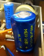
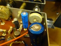
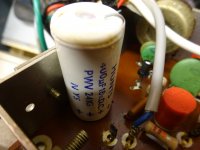
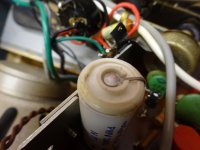
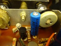
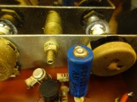
Does anyone think if I change the capacitors in the attached photos I may stand a chance of curing the buzzing noise? I don't want to throw a lot of money at it, or sub it out to someone (and have to pay them), and if it stands a decent chance, I'd like to give it a try.

I've also put a copy of this post in the analogue source section, as there may be a lot of experience there too.

Thanks, Rob

Attachments

  • DSC04160.jpg
    DSC04160.jpg
    571.7 KB · Views: 218
  • DSC04161.jpg
    DSC04161.jpg
    644.6 KB · Views: 202
  • DSC04163.jpg
    DSC04163.jpg
    570.9 KB · Views: 197
  • DSC04164.jpg
    DSC04164.jpg
    558.8 KB · Views: 200
  • DSC04165.jpg
    DSC04165.jpg
    731.3 KB · Views: 198
  • DSC04166.jpg
    DSC04166.jpg
    740.4 KB · Views: 127

Ever have a power supply/transformer fail in mid play?

Just beginning the examination after failure of one channel in my Aleph J/M@ 1/2 and 1/2 monoblocks.

Listening along when suddenly BRAAAP! and one channel goes dead. Definite smell of burned electronics in the air. Oddly, examination shows nothing on the Aleph J board burnt or crispy.

Replaced blown fuse after removing from system and hooking up to variac. Slow power up, both leds lit up but around 70-80 volts the transformer began physically humming power down.

Closer examination shows NO fried parts, smoke residue, roasted outputs, tanned resistors, nothing. As experiment, flipped power supply switch over to M2 side, still on variac and begin turning up voltage. At around same place (70 - 80 ) volts, again transformer began humming and small poof of smoke with same smell came up, but between power supply and Aleph J side of amp.

Power down, close examination, nothing. Since it occurs on both sides, Aleph J or M2 I assumed power supply at fault. Unbolt PS board from amp floor to examine back side, and nothing! No fried spots, nothing.

Looking and thinking, the only thing in the "neighborhood" of smoke was the CL-60 from power supply to chassis ground. Doesnt look cooked, but they are already black in color to begin with.

If it was the CL-60 I'm thinking the Transformer failed and CL-60 doing its job?

First step, disconnect secondart leads from rectifier blocks and repower slowly with variac, see if it still hums. (the transformer itself). If yes, problem (well, one of them) will be obvious.

Then if good, remove cap bank and add rectifiers back. If rectifiers failed, (I doubt it but who knows) replace, otherwise reconnect cap bank and test, again I doubt it, nothing swollen or funky looking.

If all checks out, which I dont think it will I will reinstall Aleph J board back in the other monoblock, which started out as Aleph J to make sure all is right with it, and order another transformer.

Sound like reasonable forensic exam? Oh, I did check out the switch which determines which amp board gets the power. All seems as normal with it.

My first First Watt clone failure.

Russellc

U3090MG VFD driver. Help needed.

Is anyone working on anything with a U3090MG 40pin dil? I need to know the dc reading (With power off) between pins 30 (ser.data) and 25 (ground) please. Pins 29 (Clock) and 30 (Data) seem to be I2C bus with 4k7 pullup resistors. I have 2 new I/C's from Littlediode and 1 from another scource that read 38 Ohm between data (30) and 25 (Ground) This cannot work surely!
I would be grateful for any advice.
Thanks,
Mike.

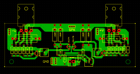
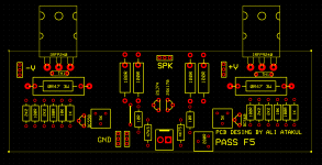
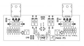
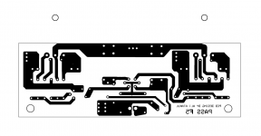
How the F5 boards look

I've wanted to do it for a long time. Finally I was able to take the time and draw the boards.

Can you see a negative factor in the layout?

I haven't energized yet. If there is an error, let me correct it now.

Attachments

  • F5.PNG
    F5.PNG
    84.5 KB · Views: 248
  • F5 TOP.PNG
    F5 TOP.PNG
    63.4 KB · Views: 252
  • 1.PNG
    1.PNG
    50 KB · Views: 251
  • 2.PNG
    2.PNG
    31.2 KB · Views: 254
  • 122471182_2735699293350953_6544932268609668836_o.jpg
    122471182_2735699293350953_6544932268609668836_o.jpg
    199.3 KB · Views: 237
  • 122432857_2735699343350948_8123363723098927417_o.jpg
    122432857_2735699343350948_8123363723098927417_o.jpg
    150.3 KB · Views: 122
  • 122281603_2736447869942762_265389756964250495_o.jpg
    122281603_2736447869942762_265389756964250495_o.jpg
    163.8 KB · Views: 146

Brass or plastic (type) pulley

Looking for thought...

I have a DIY table with a motor using a brass pulley designed for a flat belt (aka: from an older Kenwood belt drive). I am running my DIY table with an audio cassette tape as a belt and it works well enough. This said I have another motor which came from either an audio cassette deck or VCR. It has a hard plastic-like pulley that is of a narrow groove design for running a thin round or v-belt. I was thinking of trying this on on the other motor shaft to run a silk thread drive for my turntable. I wonder if any of you here have thoughts on which material is better, a wider brass pulley for a flat belt or a thinner grooved plastic pulley for a round or V belt?

Next, I was able to easily pull the plastic pulley off the motor it came with. The brass pulley currently on the motor I'm using is on tighter and I am worried about any damage to the motor if I try to pry this off. Any ideas on doing this with little fear in damaging the motor or shaft?

I really am only considering this for the curiosity of it. I am just wondering if it will improve the performance of my setup or not? The drive diameter of both pullies looks very similar and as my motor is a D.C. servo I have trim pots for fine adjusting speed control.

Thanks in advance. 😎

Restoration for Yamaha C-4 preamplifier + Sherwood s-8900A.

I have a Yamaha C-4 preamp. The problem is that, when you power it up it does nothing. And to add to that, I am seeking a ground up recap and restoration on this unit with good quality components. I also have a Sherwood S-8900A receiver that works, but also needs a complete overhaul. Is there anyone that can help me? If so, please let me know. I would be very grateful for their help.
Sincerely, In The 21st Century.:headbash::headbash::headbash:

FS Regulators and DAC stuff

Hi all,
I am moving my lab so some stuff is up for grabs.

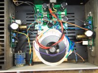
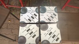
1- XMOS 384kHz DXD DSD256 high-quality USB to I2S/DSD/SPDIF converter, assembled, toghether with ES9018K2M DAC and sample rate display PCB. Assembled and tested briefly, working perfectly. 45 Euro

Audio Kits (4) - DIYINHK

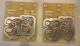
2-ALSWR Didden-Jung super regulators, 4 pcs, using AD825. Used for the above project and set to +3.3 (2pcs) +12 and -12V.
Will add 2* original Didden Jung PCBs (1 pos, 1 neg) 50 Euro

3-2 assembled PCBs and 3 base PCBs for CS8412+TDA1543 or 1545 DAC. Some documentation available, 2xCS8412 included and 1xTDA543 and 1x1545A included. 35 Euro for all

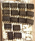
4- 16xTDA1543 DAC ICs. 25Euro for the lot

Shipping at cost, Paypal accepted. Combined purchases preferred.
Whole lot goes for 140 Euro
1+2 go for 90 Euro
3+4 go for 55 Euro

Attachments

  • DIYINK.jpg
    DIYINK.jpg
    812.8 KB · Views: 523
  • ALSWR.jpg
    ALSWR.jpg
    654.8 KB · Views: 513
  • CS8412_TDA.jpg
    CS8412_TDA.jpg
    729.7 KB · Views: 504
  • Didden-Jung_PCB.jpg
    Didden-Jung_PCB.jpg
    559.9 KB · Views: 491
  • TDA1543.jpg
    TDA1543.jpg
    129.4 KB · Views: 498

Please help with ACA hum

Greetings,

I have a couple ACA amps so I decided to use one as a headphone amp. The boards are by Rudy Ratlos as are the Jason Kuterman cap multiplier boards. The headphone is connected through 120 ohm Dale RN60 resistor, each channel. The positive side of each channel is connected to the Negative output (instead of ground when used as power amp). I seem to have read this recommendation on one of the ACA threads.

I am still getting a slight hum despite my efforts to eliminate. I have tried rotating the toroid transformer through about 90 degrees and it did lessen the hum slightly.

I attach a photo of the completed unit and would appreciate suggestions for eliminating the hum.

Thank you.

Attachments

  • PA200003.JPG
    PA200003.JPG
    475.1 KB · Views: 206

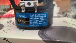
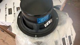
Jaycar (Response) CW2192, new, never used 5 inch mid woofers for sale in SA, Australi

I have 4 new, never used, apart for testing, Jaycar CW2192 mid woofers that I do not need anymore.
Bought them some time ago but ideas and priorities changed and I think they'll be better off with someone that has the right ideas in mind.

There are 4 drivers, sold in pairs only, so if you need a single one you better buy one from Jaycar.

Price is AU$15- per driver, or AU$30- per pair.
That is a reduction of AU$14.95 per driver from Jaycar's price.

I am in SA, in Barossa, so no postage required for Adelaide based members.
For interstate members there will be some postage (Australia Post).
Payment is Paypal preferred, I will absorb the Paypal fee.

About the drivers:
in as new condition, only tested as single drivers and also as pairs, hence you see solder residue in their +/- posts.
Very nice family of midwoofers, I've used their 4" and 6.5" with great success.
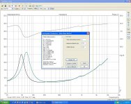
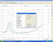
Check photos below and also individual T/S tests, done with LIMP.

Attachments

  • WP_20201024_17_41_49_Pro_LI.jpg
    WP_20201024_17_41_49_Pro_LI.jpg
    768.9 KB · Views: 98
  • WP_20201024_17_43_04_Pro_LI.jpg
    WP_20201024_17_43_04_Pro_LI.jpg
    595.5 KB · Views: 91
  • WP_20201024_17_43_50_Pro_LI.jpg
    WP_20201024_17_43_50_Pro_LI.jpg
    501.4 KB · Views: 67
  • WP_20201024_17_44_19_Pro_LI.jpg
    WP_20201024_17_44_19_Pro_LI.jpg
    453.9 KB · Views: 68
  • WP_20201024_17_44_29_Pro_LI.jpg
    WP_20201024_17_44_29_Pro_LI.jpg
    524.6 KB · Views: 64
  • cw2192 - 1.JPG
    cw2192 - 1.JPG
    166.4 KB · Views: 53
  • cw2192 - 2.JPG
    cw2192 - 2.JPG
    166.4 KB · Views: 48
  • cw2192 - 3.JPG
    cw2192 - 3.JPG
    166.4 KB · Views: 54
  • cw2192 - 4.JPG
    cw2192 - 4.JPG
    166.4 KB · Views: 59

Diode 15B

Hi there guys,

Does anyone know the exact part number of the Diode 15B-34 from the photo? When I search this I get all different kinds of diodes.
It is used on the output section of a Soundmagus 3500x (same as the excursion HXA5k)

diode number D34, D35, D37, D38

Thanks 🙂

Attachments

  • PHOTO_20201020_154025 (1).jpg
    PHOTO_20201020_154025 (1).jpg
    680.5 KB · Views: 130

NAD 3020 insert resistor help

hello to all .. first of all I apologize for my translation

I had a problem with my NAD 3020 first model
R652 as burnt, destroying Q610 / 612/614 and both power trans Q616 / 618 where they were fried.
The left channel is intact.
I will also change Q612 /Q614 to BD139 / BD140 as the original is not easily obtainable. (Changing the pinout)

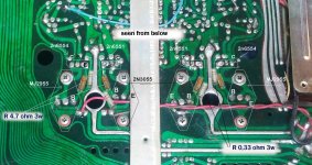
I have read from several parts and here too the advice / need to isolate the emitters and insert a 0.33 ohm 3w resistor between the emitters and the common connection point.
and also insert a 4.7 ohm 3w resistor between the drivers and the bases
Without this mod there is a risk of thermal runaway due to the newer transistors which are of epitaxial construction. The original 2955/3055 pair was hometaxial.

x to put it into practice, for me it is difficult because I am not very practical, but a great desire to learn

I ask you if this screen of mine is correct to run the mod

Attachments

  • IMG_20200820_172954_8.jpg
    IMG_20200820_172954_8.jpg
    537 KB · Views: 241

FS : Morel drivers

Barely used Morel drivers .
One pair MW142 and one pair MW166 .
I used those in my Morel Devon speakers but didn't have the chance to use the speakers for listening .
asking 100 Euro for all 4 drivers + shipping and PP fee if needed .
Drivers are in good working order.
Currently building an OB speaker and at this moment using Eltim CA-65 speakers , also with Morel drivers

Attachments

  • Morel MW142-166.jpg
    Morel MW142-166.jpg
    511.8 KB · Views: 393

15" Driver (subwoofer) repair but diagnosis first

I have a sub where the voice coil is scraping.

If I put a side load on the cone, I can get full motion w/o scraping.

INSPECTION:


Surround:

Inspection revealed something pretty weird: the OD surround is massively off center by 1/8" relative to the basket - in the direction of scraping!

The surround is in excellent condition, suspiciously so given the speaker is probably 20 years old. The ID appears to be properly glued to the cone with a hard black glue and measured concentric with the dust cover.

What is further perplexing is that the thick gasket where the surround is offset the most actually touching it, has rolled inward approximately 15 degrees lifting the surround off the basket glue - almost as if the gasket shrunk. I can't see the surround glue failing and rolling that heavy gasket.


Spyder:

Inspection of the spyder indicates the glue has failed and it is now sliding along a segment of the VC tube - it has not pulled away from the tube. The segment is closer to 45* than 90* of the tube.


Offset Direction:

The surround offset shift axis appears to be aligned with the VC glue failure.

Which way is the offset: If we look at this shift axis, the glue failure is at +R where R is the VC tube radius, and the shifted surround OD axis is at -1/8 inches. The OD surround center moved away from the glue failure.
FAILURE THEORY:

Perhaps the gasket shrunk and over the next 20 years it slowly sheared the surround/basket glue and actually failed the surround glue in shear at the highest loading point causing it to lift and roll?

Now with the surround offset and placing a constant side load on cone and torque to the VC tube, the spyder glue failed at the greatest outward shear. NOTE: Why it didn't fail at the greatest inward shear is because the cone supports the spyder in thrust.

REPAIR PROPOSAL:
  • Free surround from basket by carefully slicing though the glue
  • Find surround location that does not scrape
  • Glue spyder
  • Confirm no scraping and glue surround

Glues:
  • Spyder - gel superglue - fillet between spyder and cone, try to get on tube OD too
  • Surround - ???

Am I missing anything?

Thanks
Tom

All dc coupled 300b se design

I am designing a 300b all dc coupled tube single ended amp and would like to ask your comment on my circuit. Initially I am thinking about using TL783 to fix the current of each tube so as to maintain a stable anode output voltage to the next stage. But I later think that it should be possible to use cathode bias tech to let them maintain their anode output voltage.

Enlightened by the comment noted in DIYAUDIO I come up with this separate power rail idea for different stages in order to have the cathode bias be lower to the value which should be able to compensate the change in grid voltage. The circuit now has only 2 power rails and if this idea is feasible I should try to make the 6sn7 and 6dj8 be on separate rail too. And I guess the 2 secondary cores should completely be separated for this to work (i.e. not one core with different voltages tap). Thanks for your comment in advance.

Attachments

  • D5009CC2-C542-48A9-A13D-6E355656E26E.jpg
    D5009CC2-C542-48A9-A13D-6E355656E26E.jpg
    404.9 KB · Views: 532

Aluminium box vs sheet metal chassis

I have temporary access to a 5 axis cnc router, and for my current amplifier project I was thinking of making a fancy milled top plate to mount the tubes and transformers on. - sheet metal isn't thick enough.

To support the top plate I was going to use 8mm tick milled aluminium bars for the sides. Using the router, I can use a mortise and tenon to join the front and back to the 2 sides and secure with a few m3 screws. The top plate would be screwed down using a few m2 screws each side.

I was wondering, would this create strong enough joints or should I just go with sheet metal?

Vishay vs Takman Metal

Takman Metal wins the Gold, Vishay Zfoils do not even get the bronze,, Just got my Jadis DPL back from tech guy with Zfoils,, Cost mea fortune. Sounds like garbage, High distortion, completely destroyed my sonics which i have been spending $$$ on new caps past year., These Vishays destoyed everything i built up.
Jadis uses Takman Metal resistors for a reason, = best sound resistor on the market.

2 x XY LM3886 amp boards (completed)

Two Chinese-made XY LM3886 amp modules.

I bought these to compare/contrast with a more advanced proejct I was building.
I no longer need them. They both tested as fine on my scope, and I listened to each for a few hours on and off.

CASH or Interac e-transfer only.
NO Paypal.

Local pickup only.

Attachments

  • XY LM3886 amp modules.jpg
    XY LM3886 amp modules.jpg
    173.6 KB · Views: 275
  • XY LM3886 amp modules front facing down.jpg
    XY LM3886 amp modules front facing down.jpg
    124.4 KB · Views: 271
  • XY LM3886 amp modules-parts.jpg
    XY LM3886 amp modules-parts.jpg
    133.5 KB · Views: 264
  • XY LM3886 amp modules-PCB rear.jpg
    XY LM3886 amp modules-PCB rear.jpg
    93 KB · Views: 260

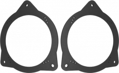
Free in Toronto area: Camry front door speaker adapters

Hi everyone:


Free to good home:
One pair of new, never used 1997-2001 Camry and 1997-2001 Lexus ES300
Front speaker adapters. Made of PVC.

These allow you to put 6.5" midbass or other speakers in the existing cutouts
in the front door. And if you sell the vehicle, or move your system to another vehicle,
you can just remove them and put the original Toyota speakers right back in easily.


Car speaker adapters.png


Available for local pickup in the Toronto, Canada area.

FS Brand New Fostex FE126En drivers and more.

Good evening everyone. I am still going through my drivers. I found another set brand new.

1. Fostex Fe126En driver brand new.
$100.00 for the pair buyer pays shipping.

2. Fostex FF225WK brand new drivers.
I will include Dayton Audios mini planner tweeters...
$150.00 for the drivers. Buyer pays shipping.

3. Fostex fe168z sigma drivers brand new. Price is negotiable. Buyer pays shipping.

4.Fostex fe208z sigma drivers. I have 3 of them brand new.The 3rd driver is 1/2 priced. Price is negotiable. Buyer pays shipping.

5. Fountek planner tweeters. Neocd2 I have 3 of them brand new. Price is negotiable. The 3rd tweeter.is 1/2 the listed price.


6. I have some mono price banana plugs and also some Dayton Audio odds and ins Banana plugs and a few other things. E mail me for prices.

7.mogami speaker cables w3103 speaker cable for sale and Canare 411s speaker cables for sale bulk as well. E mail for pricing? Jeff

Tube iron for sale

1. Refurbished Eico ST-70 Output Transformer S-32021-1. Repainted bells and new hardware. $80.

2. Custom Eico HF87/89 transformers, $49 each.

I bought two custom Eico HF87/89 Power Transformers (PN 30031) from Heyboer in 2005, back when our mains voltage was 125.

I installed both in different builds and noticed that the output voltages were low -- 5.75 on the filaments and about 162 on the HV (this transformer was intended for a voltage-doubling circuit). When I measured the linenow, it's about 120, which explains why.

These can be used as is in a higher line voltage application.

Alternately, you can add an inexpensive 6.3V filament transformer in "boost" configuration and get closer to the spec's, which are (according to SAMS):

170V @ 0.9A
6.3V @ 7.6A
75V for bias

Where I could, I spliced back the leads that I cut. The transformers were otherwise not used after initial installation.

Joe Meek VC6 Opto Comp not working

Hi everyone!

New member here. I have acquired a somewhat functional Joe Meek VC6 preamp/comp/enhancer for free off a friend as it isn't operating entirely as it should. Mainly the optical compressor section doesn't seem to be working. Signal passes through but no noticeable compression no matter what the controls are set to. The compression (threshold) control does knock down the signal as it is turned up but not in a noticeable compression type effect.

Opening up the enclosure I noticed that when the compression section is switched on and as soon as the compression control is turned off zero that the LED's that are part of the optical vactrol section stay permanently lit up regardless of any signal present. From what I understand, these should only light up when signal is present in the circuit, not stay lit up constantly with no signal present which I'm guessing i part of the reason I'm not hearing any compression effect?

Anyone here have any idea where I might troubleshoot to find the cause of this issue? Is the compression control part of the problem?

Cheers for reading everyone!

Accuphase c200x

hi i have purchased an accuphase c200x amplifier and i had to change all the electrolytic and polyester capacitors.
The line part sounds very good but the phono has a hum which I cannot remove, I have checked the transistors and integrated and it does not go away, someone has happened or can help me. I also look for the service manual which I cannot get .
Cheers

Just curious about the F4

Firstly I apologise in advance if this has been covered already. I did look and I did find one similar thread but haven't seen any posts/answers that clear this up for me.

I am very curious about the Pass amps and would love to experience the F4 for myself. After reading up on the amp I see that flea watt tube amps can be used like a pre amp for the F4, a combination that is supposed to work well. I have Tubelab Simple SE. It is approx 6 - 8w depending on tubes. It has a volume pot but no rca line outputs, only speaker binding posts. The speakers that I use are Frugal horn MA 7.3.

Would my SSE be a suitable front end for F4.? If so how would i connect it to the F4? Would I need to connect an RCA line out to the output transformers output? I am using Hammond 1628sea as I am restricted to uk TX suppliers.

Any guidance would be appreciated.

Thanks

Ariston RD11s dimensions and specs, custom build

Hello,

I have been making turntables as a hobby for the last couple of years, and have acquired a fair number of spare parts. As such, I want to find a way to throw these all together and use them up, so they stop taking up space.

The main platter/bearing system I have is from an Ariston RD11s, unfortunately without the suspension system, so I will just be hard mounting it to the plinth. I also do not have the rest of the plinth, so I cannot measure the proper distance from the pulley to the spindle of the subplatter. I do, however, still have the original flat belt pulley.

From what I have been able to measure, this is what I have:

Subplatter diameter: ~164mm
Pulley (33 rpm) diameter: ~17.9mm
Pulley (45 rpm) diameter: ~24.6mm

The motor was just a simple AC synchronous one, and I believe it operated at 300 rpm 60hz/ and 250 50hz. Attached to the set up were only two capacitors, the operational one and one I believe to keep the speakers from popping when the table was switched on. I am in North America, so I would be running at 300 rpm 60hz.

Can anyone who has an Ariston RD11s confirm that the previously provided measurements are correct, as well as:

-The distance between the pulley and the subplatter spindle
-The approximate length of the belt

Alternatively, I was considering putting the motor halfway between the outer edge of the subplatter, and the inner edge of the outer platter. This would require designing a new pulley and getting a new belt, which would require making sure that the new motor/pulley/belt combinations is properly sized to drive the whole system at an accurate 33.33/45.0 rpm.

I am aware that there are electronic solutions to fix speed accuracy and variation, but seeing as how the aim of this is to make it as simple as possible, I would rather not build an additional motor controller unit for this table.

Thanks everyone, for your help.

Help on tube IV

Hi,
this seems the right corner on diyaudio for my questions.
I want to use a 6N2P tube for IV conversion of my I-out TDA1541A DAC. I will use a 90ohm wire wound resistor. I found an implementation by Lukasz Fikus here :
http://lampizator.eu/lampizator/references/SATCH/IMG_5501.jpg
He uses a 120V transformer (although the tube can go up to 250V ???) and also a 2uF output cap.
My 2 questions are : Is it somehow better to use a lower voltage on this tube or why is he using such a low input voltage ?
Second question : I read somewhere that you should use high quality output caps. But most of my MKP caps are 2.2uF and not 2uF. Should i use two 1uF and bridge them or can i use 2,2uF without any problems ?
I have some higher quality caps from mundorf and other brands that i could use, but they are all 2,2uF. The caps that i like most at the moment (at least for passive crossovers on speakers) are Jantzen Alumen Z caps. They sound very good in high and mid ranges on crossovers (not as harsh as many of the cheaper ones). Will there also be such a big improvement over cheap caps if i use them as output caps (on passive crossovers it is) ? And the Alumen caps are also only 100vdc. Will this matter in an IV stage ?

Proof that you listened!

I didn't want to derail this thread https://www.diyaudio.com/forums/roo...usefulness-absorbtion-panels.html#post6384392 when answering post #4. So I'll ramble along here, for the sake of social research.

"We are after more enjoyable sound and not just numbers and graphs, right"

Who is "we"? Is there a common ground for the forum participants, something that turns a mass of people into a "we"?

Is that mass of people even a mass of people or more a mass of accounts?

Isn't for some the purpose to build and measure because their main interest is to achieve some spec?

Pictures or it didn't happen!! It's easy to post a graph but how do you proof you listened or proof you enjoyed listening? By posting a video of yourself listening while holding up a newspaper showing the date?

Little Dot II++ humming.

Hello everyone! I've recently come in the possession of an old Little Dot II++, the problem is that there is an audible hum (around 50 Hz, I'm in Europe so 50 Hz AC here) coming from the transformer, this wouldn't be much of a problem since I'll be wearing headphones when I'm using it if not for the fact that it is also clearly picked up by the amps and is reproduced (and I'd say it's also pretty loud) by the headphones. Things I already tried:
- Changing tubes, both power tubes and signal tubes.
- Changing cables.
- Trying different power outlets.
Unfortunately I don't know anything about electronics so I haven't been able to test anything else. As you can imagine since I'm posting here none of this helped, there is still a clear backgroud humming. If anyone could help me I'd be really glad!

F6 Clone amp

I intend building a First Watt F6 clone amplifier.

With no experience in electronics, this may be ambitious and I have numerous queries. Some are for clarification purposes.

I would appreciate input regarding the following.

Resistors.
Some are 3W, others 1/4W. Is it better to use higher wattage? For instance, a 5w used in place of a 3w and 1/2w in place of a 1/4w?

Are the resistor values specified in the DiyAudio BOM the same as the First Watt F6?
The build guide suggests some changes.
ie: R11/ 12- what is used in the First Watt amp?
R13- I would like the LED (blue) to be on the dim side. What resistor would you recommend?

Considering Takman where possible, the rest Vishay.

Capacitors.
Are these polar or non polar? Considering Audionote Kansai. Any views on these? (1000uf, 25v)

Input Jfets.
The Linear Audio Jfets available are class B... what does this mean? Class A, C?
I note the 170, 174 Jfets are tied together. Why is this?

Mosfets.
Who makes the IRFP 240 Mosfets supplied by Diyaudio? Are they branded?

The First Watt F6 amp was designed around power Jfets... but this version uses mosfets, as the power Jfets are no longer available. Not anywhere?
This site mentions that these power Jfets/ mosfets are interchangable. Is the circuit otherwise identical? ie: Simply a case of substituting mosfets for the power J Fets?
How is the amp altered sonically, and how much does this sound like the original First Watt F6? I am under the impression that transformers were primarily used for phase inversion, as the Jfets were only available in n-type. As mosfets can be both n and p type, what is the purpose of the transformers in this case?

LED.
Could leads be added to the LED’S so they can be fitted to the front panel, as per the original amp?
Seem obsolete if in the chassis.
I note the LEDs are specified as green or red. Would prefer blue... assume this is ok.

Internal wiring- maybe overkill, but is something like the Van Der Hul CS-16, FT-16 appropriate throughout? Any suggestions?

Various.
Do the First Watt amps exclude soft start and speaker protection circuits?
Does the speaker protection circuit negatively affect sound quality? Seems quite complex, does the audio signal go through the relay?
Are soldered joints preferable to spade, mechanical connections. These seem to be used.

What solder will give the best results, ie: professional smooth, shiny finish?

Power Supply.
Antek AS-3218 - 300VA 18V transformer. I understand this can be wired for 230V and is suitable for 50HZ? (My local power supply)
I Intend to use bridge rectifiers, to save space. KBPC04-25. What works better discrete diodes or these?
I note a 400kva transformer is often used. What is the spec on the First Watt F6? Is 300Kva sufficient, or is more preferable?

Chassis.
I like the Mini Dissipante, and assume the 300 x 250mm wide interior is sufficient. although I note that a larger size chassis is normally used,
with much empty space. If various chassis components are bought as separate items from Diyaudio, do the heat sinks come with predrilled fixing holes?

Also looking at other chassis options.

I’me sure more queries will come along once I get started.

Ultimate paper cone treatment

Quite possibly the best treatment to repair or refurbish vintage paper cone speakers. Not Poly, PVA, Mod Podge, Silicone or other plastic compounds, that will change the harmonic nature of a paper driver. This is a 100% natural organic formulation used to treat wood and by default paper (wood pulp).

What this is, is a result of 30 years of research, formulation and experimentation to reproduce the varnish used by master luthiers from the golden age of violin and cello building. The best varnishes would not change the natural vibration characteristics of an instrument, only seal and protect the wood. It should remain somewhat elastic for many years.This was always a highly guarded secret. I've used this to refurbish and repair vintage violins and cellos.

The same properties that make this varnish excel in restoring a vintage violin or cello, make this the best substance in refurbishing and strengthening a vintage paper cone driver that has lost it tensile strength due to age, and vibrational shock. Also helps new cones to reach their maximum potential.

This is not an off the shelf product, but a time consuming and labor intensive formulation of multiple natural compounds. Some of the ingredients are getting hard to source. It is expensive to make. This way beyond Dammer Varnish or Shellac.

I have used this many times over the years to repair, refurbish and upgrade paper cone drivers. It works better than any other treatment I've tried. You won't be disappointed in the results.

Used 50/50 with denatured alcohol. Recommend 2 coats on the front, rear and whizzer cone if it has one. One bottle will do a pair of 6.5 inch drivers. If doing 8 inch or larger, you will need 2 bottles.

I will send you application instructions when you purchase.

$25.00 firm plus shipping. Due to compounds used, I can only ship in the USA.

Attachments

  • DSCF2792.jpg
    DSCF2792.jpg
    662.7 KB · Views: 193

QSC 2150'ish build planning - feedback please

Hi,

I'm starting on a project to build LCRs, I've fell in love with the QSC SC 2150 horn. However I want to DIY it with different drivers.

So idea is to build a ported box for the LF section and use the QSC 2150 horn.

Speaker choices:

Low Freq:
Use only 1 18" woofer
Celestion FTR18-4080F
404 Not Found
I want to create a ported box of ~200 liters so it's flat until 50hz or so, I will cross with a sub for real lows
This deviates from the QSC 2150 usage of 2 15" woofers.
Use up to 500hz

Mid:
Celestion CF0617M
Celestion CF0617M - Cast Chassis Mid-Range Driver
Use from 500hz to 2khz
The QSC 2150 uses the celestion TF0615 and it's like a diff of 5db lower than my choice of the newer CF0617M

High:
Selenium D220ti 8ohm with the eminence adapter so I can get it on the horn
From 2khz to end. From the specs it appears to be a great driver with flat range.

The actual design of the real QSC SC 2150 is crossed at 500/2.2k using different drivers and the LF portion uses 2 15".

For crossovers, I see parts express has 500hz and 2k lpf/hpf filters for 8ohm. They're 2nd order. I was thinking of using these. And use an lpad for the tweeter to bring it down to level match

Should I expect surprises by using those drivers in the 2150 mid/high horn?

Would I be close enough with this design and crossover? What risks do I face? Is there anything obvious that is terrible about this? Am I out to lunch?

Thanks a bunch for any feedback.

200W Amp Simulation Advice

I am trying to simulate an 200W amp in Ltspice and measure its THD but do not know how to proceed.

Thanks to dadod for the input from his thread. The attached asc file is using his directives and the models files are from his post. I added the missing models to the Cordell-Models file.

The input section was copied from the SC200 https://www.diyaudio.com/forums/chi...ordell-super-gainclone-sc200-post5731705.html and the output of the circuit was copied from an amp by dadod. https://www.diyaudio.com/forums/solid-state/253039-unique-cfa-120-230w-amp-post3858433.html

Can anyone provide any easy to understand insight? I have tried Google and YouTube but nothing really straightforward.

There are also various errors flagged "Node N031 is floating", which I cannot understand as the connections appear complete to me.

Attachments

Best digital output card

I built a Windows-based music server that feeds directly to my DAC. I learned that digital output from the motherboard produces miserable results, so I installed a Sound Blaster Audigy 5/Rx that has optical and coaxial output, and it's much better, especially when I select Bit Accurate Playback. That left me wondering if there is another level I can attain with a different card. I think I have a general idea why the Sound Blaster is superior to the motherboard's output, but I have no idea whether one sound card would be better than another with respect to digital output. Thoughts? Experiences?

JLH 80w mosfet power amplifier - modifying it

Hello,

I am currently trying to modify a JLH mosfet amplfier. This was designed back in '82.

What I am trying to do is replace Q10 which is a VN1210M (1w) vas fet with a higher power VN1210D device. (45w). Obviously the VAS CCS and vbe transistors will have to be upgraded and probably heatsinked. Enno Borberly in his earlier designs such as the DC100, Servo 100 etc recommend driving lateral Mosfets with about 30-40mA per pair. This was because of the capacitance, apparently this improves HF THD and also the slew rate. Another thing that JLH does in his design is uses different gate resistors (presumably to match the bandwidths closer). But I would prefer to use equilisation capacitors over the N Chl mosfets as I do not think the slew rates could be symmetrical ?? (not sure on that one)

My questions is, can I replace the VN1210M with a higher power VN1210D and will this affect the compensation of the amp ie. need different compensation capacitors etc. I am not good enough to adjust this to be honest.

I have included a link to a datasheet which shows the devices in question. One minor problem is that it does not show the VN1210M by name.

Just wondered if anyone had any old supertex databooks with these devices in particular. Think I am alright though.

http://pdf.alldatasheet.com/datasheet-pdf/view/25955/SUTEX/VN1210D.html

Any help appreciatted

Kevin

Attachments

  • scan00023 (medium).jpg
    scan00023 (medium).jpg
    67.7 KB · Views: 7,766

This is either very wrong or I have still not understood diffraction from baffle edge

I am still trying to grasp all the concepts and theory of open baffle speakers, and when browsing images for inspiration, I came across this beautifully designed open baffle hybrid:
An externally hosted image should be here but it was not working when we last tested it.


Seligkeit Speaker

Now, after having read Siegfried Linkwitz "Diffraction from baffle edge" article, I must assume that the round baffle for the midrange in this OB is a very bad idea... or do I need to unlearn something

DIY Walnut box to house pair of stereo speakers and a mini amp

Hey all,
I bet this is a stupid idea, but here goes.

I want a good wireless speaker for my bedroom which the wife will approve of, so a tasteful looking single speaker (like the Audio Pro BT5 in walnut but better).

I wondered if buying a pair of small bookshelf speakers and housing them in a diy built walnut veneered box, with appropriate opening at the rear for the speaker ports and a diy front grill to cover everything. I could home a raspberry pi and amp + dac inside the box so that the box looks like an all in one except it is just a chassis for 2 x stereo speakers and a mini amp + small computer.

How daft is this idea? Is it also silly expensive in that I may as well buy a Nam Mu So Q (2) or something?

I thought it would be fun to do and means I could get some q-acoustics concept 20 or similar to go inside 😀

Stereo To Mono

Hi, so ive heard if i connect L and R together without resistor it starts fighting eachother . People told me that its almost the same like shorting two amplifier outputs together, it will work but not long .
So my question is what kind of resistor values i should use ? Also im putting 10k pot between the source and amplifier input .
Source is a bluetooth module and im using class d tpa3116 100w mono amplifier board, gonna make a bluetooth speaker. I don't need a stereo sound for my speaker because you couldnt even tell the difference 10m away from the speaker . Im using two stereo bookshelf speakers .
Thank you guys ! Much love 🙂

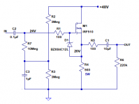
Viable Circuit? (Simple Source Follower using IRF510)

I have some IRF510 MOSFETs sitting in a drawer which I'd like to use to make simple source followers to buffer a high-ish impedance signal source to a pair of powered speakers with low-ish 10k ohm input impedance.

Does this look like a viable circuit (attached)?

Is this 'silent bias' voltage divider scheme going to work biasing an enhancement-mode MOSFET? Or will the MOSFET fail to turn on?

I also have a few IRF630 MOSFETs. Would those perform better in this usage than IRF510? Or is there practically no difference between the two types?

I'm almost completely naive to working with transistors, hence the beginner questions.

Thanks for any advice.
--

Attachments

  • IRF510_source-follower.png
    IRF510_source-follower.png
    7.1 KB · Views: 513

Aleph J problema for adjust Offset and Bias

Hello, I'Miguel from Spain, I think this is the place for technical question.

I'm building a Aleph J amplifier board and now it's time to adjust Offset and Bias. I fixed the bias resistor to 68k and swich on the amp.. then i check the volts of the exit post and see is 23.5 volts, and when I turn the Offset variable resistor, the value not change, are fixed, bouth pcb's has the same problem. Do you some experiencia with this problem ?? I check all a lot of times..... In the other hand, i see when check the exit, the positive out of the righ chanel is in the gnd exit....

Adding that the Q1A and Q1B are hot.

Thanks a lot in advance for give some light !!

I'm sure is somethink stupid from my side.

Thanks

2.54mm header blocking pins???

Hi all,

does anyone know what they call the plastci pins you can use to block 2.54mm header??

I have a cut pin on the unit that plugs into a board I'm making whihc is designed to ensure you cant plug the unit in the wrong way round. I'm sure I've see little pegs that you push into the relevant hole in the leader but I cant see anything anywhere lol.

TIA

Ian

Attachments

  • IMG_7255.jpg
    IMG_7255.jpg
    325.2 KB · Views: 127

Celestion Ditton 332 Crossover;

Hi everyone,

Last week I picked up busted 332's. I heard so many good reviews about these. Unfortunately one tweeter is not working and there is a burned resistor in crossover. I'm planning to make full maintenance including cabinets.

I'm searching for info since four days. Couldn't found any reliable information regarding crossover schematics. Is anyone have any schematic for 332's?

Also I want to try repairing hf2001 tweeter which is already down. So nothing to lose if I cannot find a way.

Another thing is I have a hard time to remove drivers.Looks like drivers doesn't glued, tight fitted, but i cannot remove them. I was able to remove two tweeters and one woofer. But I don't want to force the baffle. Any recommendation about this?

Any information will be appreciated.

Still desperately searching for xover schematic....🙁

Regards.

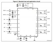
TDA7388 - DC on output at power on

I populated a board bought from ali.. which seems to me to be using datasheet scheme. For C9, C10 I used bipolar as in datasheet (the silkscreed shows them polar). For the input caps i used some 10uF muse I had around and for C7 I used a stack of 3x1000uF. The problem is I get plenty of DC on outputs when I power it on. It lasts for a few seconds (3-4) then it disappears and the music starts playing. Any ideeas what it could be? The IC is original from digi.

Attachments

  • SchemeTda.jpg
    SchemeTda.jpg
    53 KB · Views: 350
  • tda.jpg
    tda.jpg
    253.5 KB · Views: 203

HELP : Pass A3 PSU question

Hi amigos,

Just got this Pass A3 modules. I want to build a double Mono board.
But looking for the appropriate Toroïdal PSU.

Recommend PSU is : AC20V-0-AC20V

I am pretty lost with those Toroïdal stuff... I have one 300VA with 2x17V secondary but I guess it is nor the right one....

TTS300/D230/17-17V BREVE TUFVASSONS - Transformateur: toroidal | 300VA; 230VAC; 17V; 17V; 8,82A; 8,82A | TME - Composants electroniques)

The AC input board has 3 faston inputs, any idea ?

Can someone give any appropriate Link (Europe would be better) :

Pass-A3.jpg


I found this but I don't want to buy via Aliexpress...

Transformateur toroide en tissu noir GZLOZONE 500VA pour passe A3 amp 19V 0 19V 19V 0 19V L3 26 | AliExpress
Projects by fanatics, for fanatics
Get answers and advice for everyone wanting to learn the art of audio.
Join the Community
507,781
Members
7,888,195
Messages

Filter

Forum Statistics

Threads
406,227
Messages
7,888,195
Members
507,781
Latest member
Ronny2001