I've been working on a design, and hope someone is willing to review it before I start ordering parts. There's a decent chance I got it wrong somewhere.
Design goals:
- Reasonably flat response
- Good low-end extension
- Within a modest budget
The last goal is because I know I'm still a novice at this. At this stage it would most likely be a waste to spend lots on premium drivers and crossover components.
For this project I'm thinking about creating a 3-way floorstander.
First I selected the drivers I want to use. For the bass I opted for the Dayton SD215A-88. A budget-friendly driver that doesn't need much volume in a BR enclosure. For mids I went with the Dayton RS125-8. I've used this driver before, and it sounds really nice to me. For the highs I choose for the Vifa/Peerless XT25BG60. It has a smooth FR and is acclaimed for it's price/performance. One driver of each per speaker (TMW). Any comments on these choices?
I calculated the volume needed for the bass driver using WinISD. I went with the default QB3 alignment, as the required volume works perfecty for me (though the BB4 and C4 alignments were not much different).
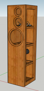
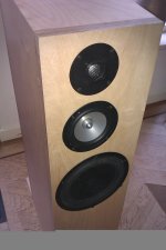
Next I designed a cabinet using Sketchup. I took the woofer magnet, bracing and BR volume into account to calculate the required woofer compartment (separated from the mid and tweeter).
Then I used VitiuxCad2 to trace the response graph of the Peerless tweeter and generate FRD and ZMA files (Dayton provides these files). I also used the 'Diffraction' tool to draw the baffle shape. For each driver I played with placement and generated an FRD file in which diffraction and baffle step are taken into account.
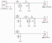
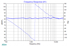
These ZMA and 'baffle compensated' FRD files were imported into XSim to design a crossover. I started off by following the instructions in the 'Introduction to designing crossovers without measurement' thread to calculate an LR2 network on each channel. Next I added L-pads to attenuate both the mid and the tweeter. To my surprise, things were looking quite promising at this point. I went on to tweak the values of components until I managed to get the FR graph within +/- 1dB between 100Hz and 20kHz. Next I made a shopping list of components, and adjusted values of the components in XSim to reflect those in the shopping list (like DCR for inductors and non-E12 values). The effect on the FR plot was very minimal. For cost and DCR reasons I went with an iron-cored inductor on the bass network. Would that be advisable in this situation? The crossover points are around 650Hz and 2900Hz.
At this point I could just go ahead with it and order all the parts. But I wonder if it would be better to just order the drivers first, build the cabinet, and measure the response of each driver unfiltered. Using the acquired data I could tweak the crossover further (or even start from scratch). But would this be worth it? Would you expect a lot of difference between real-world performance vs. simulations?
If measurement-based filter design would be recommended... I do have a Dayton iMM-6, an entry-level measurement mic. Don't know if it's fit for this purpose. Maybe I should invest in a UMIK-1? Or maybe even a Behringer ECM8000?
As mentioned earlier, it would be very much appreciated if a more experienced builder could review my design. I understand I'm asking a lot of questions.
I've learned most of what I know about designing and building speakers on the diyaudio.com forum. Youtube channels like 'Impulse Audio' and sites like audiojudgement.com also taught me a lot. But the more I learn about this stuff, the more I understand how much more there is to learn.
Design goals:
- Reasonably flat response
- Good low-end extension
- Within a modest budget
The last goal is because I know I'm still a novice at this. At this stage it would most likely be a waste to spend lots on premium drivers and crossover components.
For this project I'm thinking about creating a 3-way floorstander.
First I selected the drivers I want to use. For the bass I opted for the Dayton SD215A-88. A budget-friendly driver that doesn't need much volume in a BR enclosure. For mids I went with the Dayton RS125-8. I've used this driver before, and it sounds really nice to me. For the highs I choose for the Vifa/Peerless XT25BG60. It has a smooth FR and is acclaimed for it's price/performance. One driver of each per speaker (TMW). Any comments on these choices?
I calculated the volume needed for the bass driver using WinISD. I went with the default QB3 alignment, as the required volume works perfecty for me (though the BB4 and C4 alignments were not much different).
Next I designed a cabinet using Sketchup. I took the woofer magnet, bracing and BR volume into account to calculate the required woofer compartment (separated from the mid and tweeter).
Then I used VitiuxCad2 to trace the response graph of the Peerless tweeter and generate FRD and ZMA files (Dayton provides these files). I also used the 'Diffraction' tool to draw the baffle shape. For each driver I played with placement and generated an FRD file in which diffraction and baffle step are taken into account.
These ZMA and 'baffle compensated' FRD files were imported into XSim to design a crossover. I started off by following the instructions in the 'Introduction to designing crossovers without measurement' thread to calculate an LR2 network on each channel. Next I added L-pads to attenuate both the mid and the tweeter. To my surprise, things were looking quite promising at this point. I went on to tweak the values of components until I managed to get the FR graph within +/- 1dB between 100Hz and 20kHz. Next I made a shopping list of components, and adjusted values of the components in XSim to reflect those in the shopping list (like DCR for inductors and non-E12 values). The effect on the FR plot was very minimal. For cost and DCR reasons I went with an iron-cored inductor on the bass network. Would that be advisable in this situation? The crossover points are around 650Hz and 2900Hz.
At this point I could just go ahead with it and order all the parts. But I wonder if it would be better to just order the drivers first, build the cabinet, and measure the response of each driver unfiltered. Using the acquired data I could tweak the crossover further (or even start from scratch). But would this be worth it? Would you expect a lot of difference between real-world performance vs. simulations?
If measurement-based filter design would be recommended... I do have a Dayton iMM-6, an entry-level measurement mic. Don't know if it's fit for this purpose. Maybe I should invest in a UMIK-1? Or maybe even a Behringer ECM8000?
As mentioned earlier, it would be very much appreciated if a more experienced builder could review my design. I understand I'm asking a lot of questions.
I've learned most of what I know about designing and building speakers on the diyaudio.com forum. Youtube channels like 'Impulse Audio' and sites like audiojudgement.com also taught me a lot. But the more I learn about this stuff, the more I understand how much more there is to learn.
Attachments
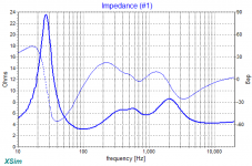
It looks very good for your first try! The dip in the impedance of the woofer down to around 3 ohms means you will need an amp that doesn't mind a lowish impedance, but it's not too bad. I'm wondering how much of that dip (if any) is influenced by the 90uF cap.
It would be good to see the individual driver responses and their phase as well.
The IMM6 is fine for doing measurements. I would get the drivers and build the cabinets first, and do the measurements to see how close to your simmed results you get, since you are interested in doing measurements anyway, before buying the crossover components.
But I have worked with a number of people over the years who have done a design using the methods you have, who have been very happy with the results without doing any measurements.
I made up an adapter for my IMM6 to be able to plug it into my mic pre. basically just a TRRS to rca cable as that mic pre has an rca input for the mic. I've also been meaning to try it on a laptop with a combo mic/headphones socket because I think it would work there (and you could use the passthrough on the IMM6 to run a cable to the amp.
Tony.
The dip in the impedance of the woofer down to around 3 ohms means you will need an amp that doesn't mind a lowish impedance, but it's not too bad.
Lowest impedance is about 3.2 ohms. I assume this is caused by the lowish impedance of the driver itself. I don't think there's not much I can do about it without hurting the (already not stellar) SPL.
It would be good to see the individual driver responses and their phase as well.
See below.
The IMM6 is fine for doing measurements. I would get the drivers and build the cabinets first, and do the measurements to see how close to your simmed results you get
Then that's what I'll do.
Again, thanks a lot for your review!
Attachments
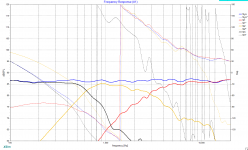
I have to admit that threw me at first, but kudos for not just going with a standard LR 2nd or fourth order on both! Third order acoustic cross on the woofer to mid, and 2nd order (possibly bessel) on the mid to tweeter! The phase matching on the mid to tweeter could be a bit better, but I would not worry about that until you have actual measurements as any offsets you have put in to the sim will be approximate, and the phase matching would likely not match your sim anyway.
I definitely think you are on the right track!
On the 3.2 ohms, I'm pretty sure it is crossover related. Looking at the impedance curve for the woofer it doesn't drop below about 6 ohms The 90 uF cap I think is the culprit, that's a big cap after a big coil. Just to get an idea if it is the cap, try either dropping its value (don't worry about the effect on the SPL, just look at what it does to the impedance) or try inserting a resistor between it and ground, maybe start with 2 ohms and see what that does to the impedance. It could also be the mid impedance in paralell, but I don't think so.
Tony.
Last edited:
"... The phase matching on the mid to tweeter could be a bit better, but I would not worry about that until you have actual measurements as any offsets you have put in to the sim will be approximate"
The acoustic centers are not aligned in the cabinet I designed, so I probably should have accounted for the offset in the sim. I didn't because I never thought of that. With my current knowledge I'm happy to achieve a nice flat FR.")
The acoustic centers are not aligned in the cabinet I designed, so I probably should have accounted for the offset in the sim. I didn't because I never thought of that. With my current knowledge I'm happy to achieve a nice flat FR.
Nice work! That first. The design resembles a setup I finished in 2012 and which still does it's job very well. I chose a sloped baffle (partly because of the looks), and the asymmetrical setup as I listen on-axis mostly.
You also paid attention to the placement of the drivers, by intent or accident, but your baffle layout I would have picked (again). The mid enclosure can be much smaller than yours though, some 2 liters are more than enough.
The crossover design seems to be fine, although I'd pick the L/M point somewhat lower, not every 8" does 1200Hz fine and you have a hiccup there at roughly -20dB. Then again, now you have no resonance at about 100Hz often encountered when using a low cutoff for the woofer in a 3-way.
For the midrange, the Dayton metals have nasty breakups at the top end (as does the ZA14 in my design). I ended up with the resonance at 9kHz under -30dB in my setup, just to be sure. Consider a small tuned cap across L2 to make a sink hole at 10kHz.
My last advice though would be: order the drivers, mount them and measure all, especially burst decay or CSD plots to check for resonances and the like (impedance measurements often reveal some too). Optimize things like damping and tuning the enclosure, measure again and import them into Xsim or VituixCAD.
Attachments
That's a subwoofer that you've selected and you are using it up past 600Hz. It may look good in a sim but it's not what I would recommend. Either bring the xo down to something like 200Hz, which may be too much to ask from the RS125 or it will probably require some pretty large filter components, or find yourself a woofer that will be happier crossing at 400-500Hz.
Maybe:
Dayton Audio DA215-8 8" Aluminum Cone Woofer
or
SB Acoustics SB20PFCR30-4 8" Paper Cone Woofer- 4 ohm- ROUND
Did wintermute mean to say that the phase could be better between the sub and the mid? Because the phase is actually very well aligned between the mid and tweeter. But since you didn't mention it in your write up, all of that could change drastically if you don't included the correct "mod delay" (in the Tune window) for the mid and the sub based upon the drivers' acoustic centers.
BTW, turn off the system phase in XSim. It doesn't tell you anything.
Last edited:
Nah I meant the mid and the tweeter, yes it is quite good below the crossover but its a bit off (nitpicking) above. The woofer to mid is third order, I always have trouble trying to see if the phase is really 90 deg apart or not.
I didn't actually look at the specs of the woofer, so good pickup jReave and MarkBakk
Tony.
I didn't actually look at the specs of the woofer, so good pickup jReave and MarkBakk
Tony.
You also paid attention to the placement of the drivers, by intent or accident, but your baffle layout I would have picked (again).
This was on purpose, to minimize baffle diffraction. VituixCad lets you play with driver positioning, showing the effects in real time.
The crossover design seems to be fine, although I'd pick the L/M point somewhat lower, not every 8" does 1200Hz fine and you have a hiccup there at roughly -20dB. Then again, now you have no resonance at about 100Hz often encountered when using a low cutoff for the woofer in a 3-way.
For the midrange, the Dayton metals have nasty breakups at the top end (as does the ZA14 in my design). I ended up with the resonance at 9kHz under -30dB in my setup, just to be sure. Consider a small tuned cap across L2 to make a sink hole at 10kHz.
Will do. Thanks for the tip.
My last advice though would be: order the drivers, mount them and measure all, especially burst decay or CSD plots to check for resonances and the like (impedance measurements often reveal some too). Optimize things like damping and tuning the enclosure, measure again and import them into Xsim or VituixCAD.
As mentioned, there's still some things for me to learn about 'burst decay or CSD plots'. As suggested I'll order the drivers first and build the cabinet. After doing some measurements we'll go from there.
Thanks a lot for your help!
That's a subwoofer that you've selected and you are using it up past 600Hz. It may look good in a sim but it's not what I would recommend. Either bring the xo down to something like 200Hz, which may be too much to ask from the RS125 or it will probably require some pretty large filter components, or find yourself a woofer that will be happier crossing at 400-500Hz.
I thought this driver would be fine, as Wolf even employs it in a 2-way: Wolf's 'Zingers'
In that design he seems to get away with just a simple 2nd order for the woofer, so assumed it should work in my application.
wintermute, nitpicking indeed!
Many people have different cabinet design philosophies. Mine is in total disagreement with the above. For the mid in a 3-way, the suggested alignment Vb's mean nothing because the LF's are rolled off anyways. Instead, you should design a rear chamber sufficiently large enough to both absorb the rear wave energy and give the driver enough space to breath. A Q of .5 may be more appropriate or for a 5" driver a minimum of about 4L is what I aim for.
Also your sketch doesn't show it but you should put a 45 degree chamfer around the backside of your mid and maybe your woofer as well. (Tip: in Sketchup, try the "follow me" function found in the "Tool" drop down menu.) When you do so, you may find that you need a little more distance to the bottom panel for the mid so the chamfer isn't blocked. Maybe true for the woofer as well.
The mid enclosure can be much smaller than yours though, some 2 liters are more than enough.
Many people have different cabinet design philosophies. Mine is in total disagreement with the above. For the mid in a 3-way, the suggested alignment Vb's mean nothing because the LF's are rolled off anyways. Instead, you should design a rear chamber sufficiently large enough to both absorb the rear wave energy and give the driver enough space to breath. A Q of .5 may be more appropriate or for a 5" driver a minimum of about 4L is what I aim for.
Also your sketch doesn't show it but you should put a 45 degree chamfer around the backside of your mid and maybe your woofer as well. (Tip: in Sketchup, try the "follow me" function found in the "Tool" drop down menu.) When you do so, you may find that you need a little more distance to the bottom panel for the mid so the chamfer isn't blocked. Maybe true for the woofer as well.
I thought this driver would be fine, as Wolf even employs it in a 2-way: Wolf's 'Zingers'
In that design he seems to get away with just a simple 2nd order for the woofer, so assumed it should work in my application.
I was almost going to add to my post - unless you have seen someone successfully use it up that high. I would still bring the xo point down lower.
I think I would still be a little happier with an 8" woofer that had a lighter moving mass though.
Oh and now I think about it I've had a terrible time getting good phase matching when doing 2nd order so yeah, I'll retract my previous comment
Understood. I'll delay any further crossover designing until I have some measurements.
Also your sketch doesn't show it but you should put a 45 degree chamfer around the backside of your mid and maybe your woofer as well.
Thanks for the tip!
No philosophies here. Just a bit of physics. The smaller the cabinet, the less troublesome standing waves inside it (they shift upwards). No back wave if dimensions are too small eh? (What is a back wave anyway). As the highpass of the mid will work together with the electroacoustic aligning, you could even design an enclosure small enough for a true acoustic 3d order with just one cap. Just use appropriate damping inside the mid enclosure. That is why I suggested measuring CSD's and BD's.Many people have different cabinet design philosophies. Mine is in total disagreement with the above. For the mid in a 3-way, the suggested alignment Vb's mean nothing because the LF's are rolled off anyways. Instead, you should design a rear chamber sufficiently large enough to both absorb the rear wave energy and give the driver enough space to breath. A Q of .5 may be more appropriate or for a 5" driver a minimum of about 4L is what I aim for.
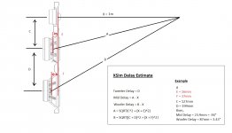
Re - acoustic centers and XSim delay
For sim purposes try these acoustic center points for your drivers:
Tweeter = 5mm
Mid = 18mm - 5mm = 13mm
Woofer = 32mm - 5mm = 27mm
Importantly, in XSim the mod delay does not equal the acoustic center differences. Instead, the delay is the difference in path length from the mic/listening point to the acoustic centers of the drivers. It is a subtle difference. Below is how to do the necessary calculations. To start, set the tweeter acoustic center as 0 and so subtract 5mm from the other drivers as I've done above.
Attachments
- Status
- This old topic is closed. If you want to reopen this topic, contact a moderator using the "Report Post" button.
- Home
- Loudspeakers
- Multi-Way
- Please review my design?