I took a closer look at your cabinet design and bracing strategy as well and I would suggest a couple of changes there.
I can't tell the exact dimensions of your cabinet subpanels, but they all appear to be pretty similar. And if your cab is made with 3/4" MDF, I would guestimate you are probably looking at subpanel resonances from around 600Hz to 1000Hz. Those will be smack dab in the passband of your midrange and just above the range of your woofer.
As such I would suggest 1 horizontal and 1 vertical window brace tied together in the middle for the mid enclosure, plus damping and a good insulation strategy. That should push the resonances up into the range above 1000Hz where there is less music energy and insulation works a little better as well. Place the braces off the center lines if you can.
For the woofers, I would add a 3rd horizontal brace just to be extra cautious and I would stiffen them up by tying them together with an additional vertical brace. Vary the height of each subpanel as well so each one doesn't have the exact same resonance frequency. That should send the resonances further up above the xo point so there won't be any energy there to excite them at all. To also mitigate any vertical standing waves in the woofer chamber, it will help if you offset the openings in the braces so there is never a clear vertical path from the top of the woofer chamber to the bottom. Damping should be unnecessary but lining the walls with something like felt would be a good idea.
Returning to this topic, I wanted to first say thanks hifijim for this explanation that makes sense to someone without a science or physics or engineering background. I appreciate that.
Now what's not clear to me still is what the difference in behavior or effect is between the pressure cycles and a true wave if there is any. What seems to be implied is that the pressure wave is not attenuated with insulation. Perhaps also not reflected off the back panel. I'm not sure if it's being implied that transmission of the pressure wave through a medium is unaffected by the medium's physical properties. Or likewise if a panel or subpanel's resonance behavior is affected differently by the 2 different types of energy.
The distinction between wave and a sinusoidal pressure cycle mostly relates to reflection and diffraction. If the enclosure is too small to support a wavelength, there is not going to be any bouncing of sound off the rear wall, and the internal shape has negligible impact on the sound field in the cabinet.
Take an example of a 10 x 12 x 17 inch (internal) box with a woofer. The woofer begins playing 250 Hz. The wavelength is 54 inch, and half wavelength is 27 inches. What is happening inside the box? Well, the speed of sound is 13500 in/sec, so when the signal starts, a pressure pulse comes off the back of the cone. It spans the 10 inch distance in 0.74 ms, and in that time the 250 Hz signal has moved through 66 degrees of phase. It is still compressing. At 0.9 ms the 12 inch distance is spanned. At 1.3 ms the 17 inch dimension is spanned, and at this point the 250 Hz signal is at 113 degrees. So the cone is at 113 degrees, but the farthest dimension of the box (17 inches) is at 0 degrees because the pressure pulse has just reached it. There is no cancellation when a signal at 0 degress blends with a signal at 113 degrees. When the cone is moving into the box at 250 Hz, the entire air volume of the box is undergoing compression, although there is some phase delay at the various walls. Likewise when the cone moves out of the box at 250 Hz, the opposite happens and everything undergoes rarefaction.
Now if we go up to 2500 hz, well that is entirely different. the wavelength is 5.4 inches, so there will be bouncing of waves off of the walls. Any brace, magnet, or object that is larger than 2.7 inches can reflect or diffract the sound. There will be various nodes of cancellation and summation within the box.
What seems to be implied is that the pressure wave is not attenuated with insulation.
Thankfully this does not seem to be the case. If you stuffed the above box with foam or fibers that have 50% absorption at 250 Hz, it will be exactly that effective, even though wave behavior has not developped in the box. Why? Well sound is pressure cycles and velocity cycles. The velocity cycle is 90 degrees out of phase with the pressure cycle, so when the pressure is at a max or min, the velocity is 0... likewise, when the velocity is at a maximum, the pressure is at nominal (i.e. crossing the zero axis). Sound absorption works by sucking energy out of the air velocity. It slows down the air velocity, so the next pressure cycle (90 degrees later) is lower... there is less energy available to compress the air because the fibers slowed the velocity down. Just for clarity, when a speaker diaphragm is making sound, the velocity is 90 degrees ahead of the pressure.
I know this was long-winded, but sometimes it is best to get into the physics in order to explain something. Really good question by the way... it made me think... it made me dig out my physics text book from 34 years ago .
hifijim, once again thank you kindly. That is an excellent answer. Admittedly some of it is still over my head but you've explained it well enough for me to get the jist of it. Thank you for taking the time to do so.
Maybe I need more time to digest it, but so far I still think that a larger chamber for a 3-way mid is the way to go. Room for the driver to breath. Room for the air spring to remain appropriately loose. Room for some manner of panel damping . And room for enough insulation to sufficiently attenuate sound transmission through panel walls and the excitation of panel resonances.
Maybe I need more time to digest it, but so far I still think that a larger chamber for a 3-way mid is the way to go. Room for the driver to breath. Room for the air spring to remain appropriately loose. Room for some manner of panel damping . And room for enough insulation to sufficiently attenuate sound transmission through panel walls and the excitation of panel resonances.
[...] Perhaps I should start a new thread if this is deemed too far off topic.
Please don't, this is relevant to me for the mid chamber design. And pretty educational. 🙂
I took a closer look at your cabinet design and bracing strategy as well and I would suggest a couple of changes there. [...]
Thanks, I'll make sure to apply your recommendations in my design. I did space the braces evenly because of a pointless (in this case even detrimental) tendency towards symmetry.
The distinction between wave and a sinusoidal pressure cycle mostly relates to reflection and diffraction. [...]
Thanks hifijim for sharing your valuable insights, but to be honest I'm struggling on how to apply all this theory. Would I be wrong to conclude that the inner dimensions of the mid chamber should be smaller than the wavelength of the highest frequency in the passband (with some margin)?
Maybe I need more time to digest it, but so far I still think that a larger chamber for a 3-way mid is the way to go. Room for the driver to breath. Room for the air spring to remain appropriately loose. Room for some manner of panel damping . And room for enough insulation to sufficiently attenuate sound transmission through panel walls and the excitation of panel resonances.
....
Would I be wrong to conclude that the inner dimensions of the mid chamber should be smaller than the wavelength of the highest frequency in the passband (with some margin)?
I did not mean to imply that a midrange chamber should be small, or smaller than the smallest wavelength of the mid driver pass band. That would actually be pretty hard to do.
jReave - I agree with you that a mid chamber should be as large as practical. I asked this same question on this forum about a year ago, The consensus was that bigger was better. The best advice I got was to size the chamber to be at least as large as a Qtc=0.7 sealed box. This seems reasonable, it seems intuitively acceptable. In the case of my 6 inch mid, it resulted in a ~11 liter enclosure. No real hard and fast rules, just a guideline.
Ideally the mid driver should radiate into a chamber that is so large that it mimics open space. This is not practical.
My point was that for much of the mid drivers range, it is operating in a pressure chamber. But at the upper end of its range, there are definitely reflections and potentially standing waves (acoustic resonances).
This is not all bad, since fiber and foam stuffing is highly effective at higher frequencies... generally by 800 Hz the stuffing is at 100% absorption. Augerpro's experiments show wool, shredded denim, and melamine foam are highly effective, they reduce acoustic resonances to almost nothing. But there can be no doubt that a bigger chamber means more space to radiate into, more stuffing material.
Consider that calculating on Q=0.7 is rather pointless as you will install a highpass filter (that most likely will cutoff way above fc). Way back I had the same presumptions about mid enclosures, these days I focus on good damping, a form factor that will not give me too many standing waves (I like wedges) and in case of passive crossovers, a volume that complies with an acoustic tuning that will let the electric crossover do its work properly.
[...] Ideally the mid driver should radiate into a chamber that is so large that it mimics open space. This is not practical. [...]
As a Q=0.7 would translate to about 1.5L (or 0.05 ft3) for my mid driver I'll probably be okay with the mid chamber as it is (about 12L or 0.42 ft3).
One thing that bothered me about the Qtc=0.7 rule of thumb is that it might result in too small of an enclosure when the mid driver Qts is low. Take two 5 inch drivers for example, one with a Qts of 0.45 and the other with a Qts of 0.27... The rule of thumb would dictate the second driver get a smaller enclosure... but if both are being used as midrange drivers and both have the same Sd surface area, shouldn't they both need a similar enclosure size?
12 liter is a good volume for your mid.
12 liter is a good volume for your mid.
When is a mid enclosure too small? The air enclosed will act as a spring on the cone. The damping of the motor and the highpass filter will suppress any resonance. That works until the enclosure gets big enough and standing waves will introduce nonlinear behavior.
I think that acoustic absorption combined with sensible dimensions can mitigate standing waves to the point of inaudible.
Yes, the box is going to look huge at midrange frequencies regardless.
Standing waves are not going to be non-linear. You won't identify them through harmonic distortion.
Standing waves are not going to be non-linear. You won't identify them through harmonic distortion.
I just ordered the drivers. Next is to order wood and build the speaker. That will take me some time. Have been (and will continue to) read up on doing measurements. Seems to me like I need some extra hardware for measuring impedance (either DATS or fabricate something myself, probably the latter).
Very easy to fabricate something yourself and use REW to do the impedance measurements. You basically just need a 3.5mm TRS cable and a resistor in reality 🙂
Cables
This assumes however that you do have a sound card with line in (and that uses 3.5mm TRS 😉 ). Unfortunately (as far as I am aware) there isn't a way to do it with a mic in input on a laptop. I know there was a thread on here where someone was trying to develop a method to do that, but I can't recall if he was successful.
edit: note that REW (and ARTA) recommend using a 100 ohm resistor rather that the 10 ohm shown in Claudio's page. I actually use a Walin Jig II, and it has an 8 ohm resistor, but I do occasionally get some odd results with certain drivers, and that may be due to the low value of the reference resistor.
Tony.
Last edited:
Yes, but why 12l or 800 cubic inches and why not 88?
I think a larger midrange enclosure sounds better... assuming we avoid structural resonances, which is more complicated as enclosures get bigger. But "complicated" does not mean "impossible", it just takes some care and effort.
I think a larger midrange enclosure sounds better because the energy density within the chamber is lower. Lower mW/cm^3. Sound absorption works better when it is thicker, and with 88 cubic inches, there is not a lot of thickness available.
Many people believe that a midrange transmission line is the ideal enclosure shape. I think we can get very close to that performance with a simple box shape, if it is large enough, and if it is stuffed properly.
Certainly 12 liters is more than enough in this case...
Very easy to fabricate something yourself and use REW to do the impedance measurements. You basically just need a 3.5mm TRS cable and a resistor in reality 🙂
Cables
Thanks! That won't be a problem. Will need an external USB soundcard though, as I only have laptops. Certainly ebay will have numerous options.
For hifijim again on the internal reflection question, I'm just wondering if there is any chance if perhaps a half wavelength, so just 1 complete peak or a trough of the wave inside the cabinet would be large enough to be reflected back towards the source.
And additionally I was wondering if you might know - if we use bracing to break up standing waves inside the cabinet, at what point are the cutouts (circular, rectangular or triangular) going to be large enough to defeat that purpose and allow the standing wave to form again?
Now looking at the OP's 12L mid chamber, let's do some math. I recon for 12L we are probably looking at interior dimensions somewhere in the neighborhood of about 8.5" x 9" x 9.5". And let's guestimate the following:
- driver and xo volume: ~.5L
- 1 vertical and 1 horizontal front to back brace: ~1L (about half the volume of solid 3/4" board lost to cutouts)
- 1/2" damping, either extensional or CLD, on all panel walls: ~2.75L
So that's about 4.25L lost right there, so now we are down to ~7.75L.
If we want to leave a bubble of room behind the driver for it to 'breathe', how much should that be? For a 5" driver, I might say 5" x 5" x 5" which is another 2L. Now we are left with 5.75L to fill with stuffing.
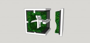
My personal strategy is to combine different densities of stuffing. I start with high density mineral wool (6lb/cu ft) which I get in 1.5" thickness which if we throw that on 5 panel surfaces (sides, top, bottom and back) will be about 6.5L. Which is already too much. So maybe go with 3/4" stuffing on the bottom panel and we're probably going to need to cut away some material around the sides of the mid driver, so minus 1.5L for a 5L total now which leaves just a little bit of room for the next medium density layer of something like felt or foam and then a lighter stuffing like polyester while maintaining that bubble of space behind the driver to breathe. Maybe even enough room for a 2nd layer of rockwool on the back panel to ensure the longest dimension standing wave (~1600Hz?) is taken care of.
That's one way to make 12L look kind of small for a 5" driver anyways. Attached is a rough sketch of the above just with the damping, bracing and 1st layer of insulation to give a visual if needed.
In terms of the compliance of the sealed air spring vs the compliance of the driver suspension which I was mentioning before, I had to go back to the text books to find the pretty simple rule of thumb that the transition between the 2 different compliance forces occurs at about Vas/3 for the driver in question. That is, the transition occurs when the compliance ratio is equal to 3, where the compliance ratio = Vas/Vb. Less than 3, the driver suspension is the primary resistive and restoring force to cone motion. Greater than 3, the stiffness of the air spring becomes greater than that of the suspension.
To give ourselves a decent margin of error, let's call the minimum Vb for the mid equal to Vas/2. In this case for the Dayton RS150-8, Vas is 4.8L which means the driver has a pretty stiff suspension to start off with, so it won't take a very large volume of sealed air (4.8/2 = 2.4L) before the stiffness of the air spring is less than the stiffness of the driver.
So this is pretty much of a non issue for this driver when we are talking about a Vb of ~12L. Anything larger than 2.4L and we can be assured that the box is not adding anything to the stiffness of the driver.
And additionally I was wondering if you might know - if we use bracing to break up standing waves inside the cabinet, at what point are the cutouts (circular, rectangular or triangular) going to be large enough to defeat that purpose and allow the standing wave to form again?
Now looking at the OP's 12L mid chamber, let's do some math. I recon for 12L we are probably looking at interior dimensions somewhere in the neighborhood of about 8.5" x 9" x 9.5". And let's guestimate the following:
- driver and xo volume: ~.5L
- 1 vertical and 1 horizontal front to back brace: ~1L (about half the volume of solid 3/4" board lost to cutouts)
- 1/2" damping, either extensional or CLD, on all panel walls: ~2.75L
So that's about 4.25L lost right there, so now we are down to ~7.75L.
If we want to leave a bubble of room behind the driver for it to 'breathe', how much should that be? For a 5" driver, I might say 5" x 5" x 5" which is another 2L. Now we are left with 5.75L to fill with stuffing.
My personal strategy is to combine different densities of stuffing. I start with high density mineral wool (6lb/cu ft) which I get in 1.5" thickness which if we throw that on 5 panel surfaces (sides, top, bottom and back) will be about 6.5L. Which is already too much. So maybe go with 3/4" stuffing on the bottom panel and we're probably going to need to cut away some material around the sides of the mid driver, so minus 1.5L for a 5L total now which leaves just a little bit of room for the next medium density layer of something like felt or foam and then a lighter stuffing like polyester while maintaining that bubble of space behind the driver to breathe. Maybe even enough room for a 2nd layer of rockwool on the back panel to ensure the longest dimension standing wave (~1600Hz?) is taken care of.
That's one way to make 12L look kind of small for a 5" driver anyways. Attached is a rough sketch of the above just with the damping, bracing and 1st layer of insulation to give a visual if needed.
In terms of the compliance of the sealed air spring vs the compliance of the driver suspension which I was mentioning before, I had to go back to the text books to find the pretty simple rule of thumb that the transition between the 2 different compliance forces occurs at about Vas/3 for the driver in question. That is, the transition occurs when the compliance ratio is equal to 3, where the compliance ratio = Vas/Vb. Less than 3, the driver suspension is the primary resistive and restoring force to cone motion. Greater than 3, the stiffness of the air spring becomes greater than that of the suspension.
To give ourselves a decent margin of error, let's call the minimum Vb for the mid equal to Vas/2. In this case for the Dayton RS150-8, Vas is 4.8L which means the driver has a pretty stiff suspension to start off with, so it won't take a very large volume of sealed air (4.8/2 = 2.4L) before the stiffness of the air spring is less than the stiffness of the driver.
So this is pretty much of a non issue for this driver when we are talking about a Vb of ~12L. Anything larger than 2.4L and we can be assured that the box is not adding anything to the stiffness of the driver.
Attachments
What is the reason? Maybe base it on Vas..If we want to leave a bubble of room behind the driver for it to 'breathe', how much should that be?
- Home
- Loudspeakers
- Multi-Way
- Please review my design?