Damping Materials

Howdy,

If this should be in a different thread please feel free to move this.

I'm having trouble sourcing the Ultra Touch felt that Dave recommends in the Frugal Horn builds. It seems that I can get 2" or 3" thick pieces, but not half inch. Also It seems like Boded Logic is having production issues, at least according to one of the distributers I spoke with. In looking for alternatives, I wonder what really matters in the properties of the felt. There are many things out there to use and does the type of felt used really affect the sound quality of the speaker?

I've found 1/2" thick polyester felt for auto carpet underlayment that is reasonably priced. Does the poly give a different sound that cotton or wool? What about Homasote? That is 1/2" thick and while a rigid board is easy to work with. I appreciate any help you all can provide.

Denon 3803 repair..........something has changed.

Hello All,

I am looking for help understanding what happened to my amplifier.

My amp is a Denon 3803 and I have been the only owner since new. It has been set-up in my listening room for years without a glitch. After not having used the system for quite a while my GF wanted to move our system to a different room. So after setting it all up and powering on, it sounded uninspired..............then I tried to turn it up.

I am experiencing something that I cannot even label, so I will try to describe the issue in hopes of narrowing it down. When listening at normal volumes it sounds as if it is missing the mids, all I hear are lows and highs. It sounds decent without noticeable distortion. When I turn it up beyond -5 the sub starts to lose control and is constantly moving in and out at full excursion. It actually starts making things shimmy in the room. The only way I can make it stop its to lower the volume to almost nothing until the sub regains control. I NEVER had this happen in the past and it is utterly unusable.

I verified that it is the amp as I swapped it out with a KNOWN GOOD amp from my neighbor. His amp does not make things sound as my Denon, no matter how high I push it.........things sound great!! Mids are present and the sound is exceptional with very well controlled bass.

I performed the factory reset and things are the same as before. I have triple checked ALL connections. We swapped out the amp and all connections 3 times. Every time the spare amp worked flawlessly and the Denon exhibited the same poor behavior.

I am an electronics maker as a hobby and have solid soldering skills and all the tools to work on SMD parts. I have performed a cursory inspection of all caps, fuses, and generally looking for anything electronically suspicious. All "looks" normal. All fuses are intact and capable of conducting current. I have the actual factory "service" manual with schematics and parts lists.

I am so disappointed with this as I simply fell in love with the warm and accurate delivery of my Denon. I hesitate to simply throw it in the trash and buy new as I know how darned expensive it will be to match or exceed the specs and sound of this OLD Denon. And apparently the old is worth so little that it makes this even more difficult. I would love to fix this one and see how long it lasts.

Any help or thoughts would be greatly appreciated.

Cheers,

David

Supplemental subwoofer

Hi,

I built my own pair of electrostatic panels and they measure about 200 cm x 68 cm. (see topic: https://www.diyaudio.com/forums/planars-and-exotics/357561-stats-model-4-a.html)

I've read about some electrostatic panel users who supplement them with a magnetic subwoofer, Like Jazzman who uses a ripole subwoofer: Jazzman's DIY Electrostatic Loudspeaker Page: Ripole Subwoofers:

I'm wondering if in my case it makes sense to build a set of these ripole subwoofers? The initial idea of my stats was to make them rather big in order to get enough low frequency range. And even though I'm quite satisfied with their low range performance, compared to my boxed speakers they lack a little puch.

Any idea if it would make sense to built such a (ripole) subwoofer, as my stats are already quite big panels?

Bias will not adjust one channel

Hello everyone. Happy New Year. I Installed the TSE back into my system after changing the coupling caps back to the Audiocap Theta from the Clarity CAP MA that were in there. It has been playing for the last 3 weeks. I swapped the 45 tubes to a pair of Westinghouse I got from FleaBay. I went to check bias and the R channel reads 1.2 and does not respond to adjustment. I shut down when adjustment could not be done. It played fine last night.
I tried a couple different 45 tube pairs and same result.

Input impedance of VU meter driver boards for tube preamp

I have added VU-like meters to my tube pre-amp output, just to have a nice visualisation of loudness. I have used this driver board and meters 2pcs Analog VU Meter Panel Kit Backlit Decibel/Level Tester with VU Driver Board 782429278986 | eBay. The preamp is an aikido design with 6cg7, so it has a Zo for the 6cg7 700ohm and of course, is capacitor coupled to the next stages. Assuming that the driver board of the VU meters is a buffer with quite high input impedance there should not be a problem ton parallelize it with my power amps (push-pull KT88 with 100k input impedance).
But is this really the case? Has anyone used any of these on the OUTPUT of a tube preamp (I want it to change with volume control)?
Has anyone any idea on the input impedance of these or similar driver boards? For example, I might need to change coupling capacitors in order to lower the corner frequency of the high pass filter. Any info would be highly appreciated 🙂

Sony TA-F5000 + Marantz MA-22 = Hum and Buzz

Hi,

hope someone could give me clue, what’s the cause of hum and buzz in my system.

Situation is as follows:

Sony TA-F5000 integrated amp with 3 prong IEC detachable cord
Connection via RCA cables from Sony pre-outs to inputs of two Marantz MA-22 mono blocks
2x Marantz MA-22s with 2 prong non-detachable power cords
Power connection to high quality power strip which itself is connected to one grounded wall outlet
Speakers connected to Marantz MA-22s

This set up has very audible and disturbing buzz from loudspeakers, spectrum shows peaks every 50Hz starting from 50Hz to kHz region with largest energy peak at 150Hz.

I tried to narrow down the problem, the findings so far:
- Volume, balance, bass and treble attenuators on Sony doesn’t affect the buzz in volume or frequency at all
- Switching the inputs or disconnecting all inputs Sony - same hum
- Plugging all devices to separate dedicated wall outlets, turning power plugs in outlets in different combinations -> still same hum
- Using different RCA cables, cheap or solid, or turning RCA plugs for better contact -> same hum
- Disconnect RCA cables from Marantz - no hum
- Shorten Marantz RCA inputs - no hum
- Shorten Marantz RCA inputs with 120 ohm resistor - no hum
- Connect portable battery powered player to Marantz - no hum
- Connect speakers or headphones to Sony - no hum

So what is this? No hum with portable battery powered player indicates a potential ground loop, but the only connection to the real ground is via Sony 3 prong plug, so it might be amp internal loop. Both amps are unmodified and otherwise untouched, power cords are original, RCA posts are original, ground screws in the amps tightened, as far as a can tell. Marantz's bias is OK according to service manual at 50mV, very little DC offset of 20MV is present at loudspeaker terminals.
Could it be some dried out electrolytics in one of the amps? Or is it some badly implemented grounding in one of the amps?

Attached are schematics of both amps.
Help and ideas are greatly appreciated!

Cheers
Daniel

Attachments

  • Sony ta-f5000 schematic.jpg
    Sony ta-f5000 schematic.jpg
    1 MB · Views: 169
  • Sony ta-f5000 exploded chassis.jpg
    Sony ta-f5000 exploded chassis.jpg
    275.3 KB · Views: 121
  • Sony ta-f5000 exploded front.jpg
    Sony ta-f5000 exploded front.jpg
    198.1 KB · Views: 118
  • Marantz MA-22 schematic.jpg
    Marantz MA-22 schematic.jpg
    551.9 KB · Views: 208
  • Marantz MA-22 exploded.jpg
    Marantz MA-22 exploded.jpg
    543.2 KB · Views: 155

tseii popping fuses

So this morning i turned my amp on and a few seconds later i got a loud pop through the speakers and no power to the amp. I checked and the fuse was blown. I tried swapping the fuse and it blew again as soon as I turned the amp on. I swapped out the recitfier tube and the fuse and again it popped as soon as i turned the power on. I pulled the board and nothing looks obviously damaged. There is some heat discoloration around r6 on the pcb but other than that everything looks normal.

I remembered reading about cogitechs issue that eneded up being his power transformer so i checked mine and Im reading very small resistance across the heater windings but im getting 75ohm across the hv winding. Is this normal or a sign of a potential issue? Im also getting between 70k-120k between the different windings on the secondary windings. The edcor xrpw178 that Im using has always run pretty hot and I wondered if it was a matter of time before it failed.

Im not really sure what else to check on this thing so Im all ears if anyone has any suggestions on where to start the troubleshooting. Thanks

Maximum choke size in LC input rectifier

Hello All,

Is their a practical limit to the inductance of the choke used in a choke input filter after a rectifier?

I am trying to understand the attached graph for the max rating of an EZ81 using a choke input filter.

It seems to suggest that the larger the coke (in henries) used the lower the max output current rating is at a given voltage. I have never seen this mentioned before.

Am I just misinterpreting the graph?

Thank in advance for your advice.

Best regards,
John


3E02A4F6-8ADC-4CA4-8659-CCD381F42520.jpeg

My Fostex FF85Wk in a ported boxes does it get any better?

Good Evening everyone. I thought I would share these boxes I made for the Fostex FF85WK drivers.
I made these for my wife..Not perfect because.of lack of tool availability and time and a place I could build them. I have all top shelf parts and felt and wire and binding post and felt on the back of the magnet. I soldered all wires point to point soldering. The bottom feet are from home depot..They keep the boxes from moving. So I really enjoyed listing to Chet Atkins Christmas Album on Pandora. I used top of the line wire I stripped and made my self. All mono price coonecter ends that are all gold cooper coded on the wire ends. I played on a older Nad integrated amplifier through my phone for now. It sounded very nice and a nice sound stage. I had them against a brick wall but, I heard most of the notes but, the lowest bass. This me has 90% of what am looking for in a full range driver. Here are a few pictures to go with my project. David from planet 10 was right these are a real treat to listen to.. My wife loves them. She said they are the right size and sound and she can listen to her music now. So on to next project? Can the Mark Audios Alpair drivers go toe to toe with this Fostex drivers? I will find out?. Jeff

Attachments

  • 16074836459978402269891980691475.jpg
    16074836459978402269891980691475.jpg
    835.9 KB · Views: 778
  • PXL_20201209_024435876.jpg
    PXL_20201209_024435876.jpg
    975.3 KB · Views: 753
  • PXL_20201209_024519225.jpg
    PXL_20201209_024519225.jpg
    895.3 KB · Views: 741
  • PXL_20201209_024534515.jpg
    PXL_20201209_024534515.jpg
    924.8 KB · Views: 723

FS: UGS Up amplifier PCB´s (upgraded version)

Hi.
anybody interested in some UGS UP amplifier (upgraded version)?
full set including:


2 x PSU
2 x amp-boards
1 x VU meter
1 x Trafo softstart


i have finished my UP and it works flawless and sounds phantastic...


price would be 70€ (excluded shipping)


Regars
Slavko

Attachments

  • IMG_0239.jpg
    IMG_0239.jpg
    166.7 KB · Views: 322
  • IMG_0240.jpg
    IMG_0240.jpg
    168 KB · Views: 323
  • IMG_0241.jpg
    IMG_0241.jpg
    124.2 KB · Views: 330
  • IMG_0242.jpg
    IMG_0242.jpg
    166.8 KB · Views: 321
  • IMG_0243.jpg
    IMG_0243.jpg
    157.5 KB · Views: 312

Service Manuals for Panasonic RX-D55GC

Hi Everyone,

I'm trying to find some Panasonic service manuals for my RX-D55GC Boombox.
The service manuals in question are:

Original Service Manual: PSG1005031CE
Supplemental Manual: PSG1012007SE

I tried checking out www.eserviceinfo.com and these service manuals are not listed. I've been searching around on the internet and can't find them anywhere. Any ideas where I might be able to get these service manuals?
Thank you!

BoxSim english tutorial or alternative?

I want to design a slot-ported vented sub enclosure. I'm familiar with HornResp and WinISD (so far), but I've heard that BoxSim entertains more in the way of port geometry specifics. I've tried and failed to find end corrections (k) and other information about slot port tuning, and BoxSim came up as a suggestion. I've seen a bit of BoxSim that seemed to have a pretty advanced slot port design capability, so I decided to give it a spin.
I downloaded it and tried using it, but after getting yelled at in German a couple of times, I'm in search of a tutorial. Maybe my Googling skills suck, but I wasn't really able to find much. There's info out there, but it's focused on crossover design, is in German or Russian or is 10 years old (or all of the above).
Suggestions? Thanks a bunch!!
-Mack

Greetings from Belgium

Hey everyone,

I've been browsing the forum for some times now, trying to get acquainted with aspects of DIY audio building.

I'm slowly getting started with electronics, trying to allocate one hour each day to read The Art of Electronics. I'm slowly getting the hang of it. This is very far from my field of study. I'm a visual artist, with an interest in audio and tinkering that started out when I was 14 and fell in love with electronic music. As my tastes have matured over the years, I found myself asking more and more from my equipment.

The year 2020, for obvious reasons, have left me with an unquenchable need to solder, assemble, fine-tune my own equipment.

As of now, I've built a few cables, and I'm in the final steps of designing my own high-end digital audio player to use on-the-go. I'll post about it when it's finished, perhaps it will be of interest to some of you. It's a screenless device, controlled with any smartphone, with an uncompromising onboard DAC and 1TB of storage, that doubles down as a Roon endpoint when at home.

I'm eager to learn more from you guys!

A good instrument dial printing application

I need to create a new scale for a galvanometer, but I cannot find something suitable.
This one for example:
Design and Print Full Scale Custom Gauge Face Templates - Metric and Inch
does lots of things, but not what I need: I want a ruler-type scale 30mm long, full-scale 10.0 and division each unit, plus tick at 0.5 unit and the 5.0 mark enhanced.
I do not need great sophistication, just a scale and digits I can print the size I want.

Some years ago, I had stumbled upon a suitable soft, but I cannot locate it now.

I could do it all by myself, with Word or anything else, but a dedicated program would be easier

Musicman Preamp woes !!

Hi , I recently bought a musicman hd130 guitar amplifier ....I bought it as a challenge as the board had been disconected and it was operating as a slave with its source coming from an external preamp ...

It also had a vox ac30 output transformer fitted to it which was strange to say the least....so the way i went about it was to turn the voltage multiplier into a bridge rectifier and use it as 360vdc supplying 4 6v6gt tubes which is a better choice than the original 4 x el34 with a plate supply of 720vdc

that part of the unit is fine now and ready to go but the problem lies with the preamp section ( see schematic picture )....i'm getting 62vdc at the supply onto the board which is regulating at 31-32vdc .....

Here is the issue I cant get an audio signal past any of the LM307H I'Cs....i dont have a tone generator or an oscilloscope so the best I could come up with is an ipod pluged into a channel and using a coupling cap plugged into another amp I followed the signal path until it ends ..... and it ends at the LM307H chips

And what is the function of the two diodes before entering the 307's ...

I may have overlooked some issue here , why would all the LM307H be dead ? as I tried each one in the first slot in channel one and not one let a signal through ?

Can anyone suggest a better way to test the board with what I have , it would seem the LM307's are dead and is 31vdc the right operating voltage ?

How would I test the IC with a multimeter ?

Since the LM307's are outdated and not highly regarded I was going to substitute these units with NE5534 as others have as there are no LM307H available in Australia.

I would love to hear from someone who has had some experience with these matters.....as a tube amp builder I do ok but as these I'Cs go I'm quite a novice at this point

Attachments

  • musicman-hd130-w-12ax7-phase-inverter 1.jpg
    musicman-hd130-w-12ax7-phase-inverter 1.jpg
    873.1 KB · Views: 465
  • musicman1.jpg
    musicman1.jpg
    296 KB · Views: 397

Basic Question about odd results in LTSpice

I didn't want to pollute the spice model thread with this.

While I wait for parts I have been playing with Spice models. Specifically variations on Millett's PP circuit using the Harmonic Equalizer connection. The circuit runs fine when I attempt to use reasonable resistances but I noticed that no matter what values I used I couldn't force clipping. The output was always a perfect sine wave.

So I turned the bias into a voltage source (breaking the Equalizer connection at the same time) and started really stress testing it. While the Vpp output changed with bias it was always a perfect sine wave no matter how hot or cold I set the operating point. Similarly the two plate voltages were always perfect sine curves 180 degrees out of phase. This does not seem right.

I've attached screen shots for the two plate voltages plus the output taken at zero bias. Not that the peak to peak values change but the behavior is the same with different tube models or if I switch to using a triode symbol and triode models. I'm also getting more change in voltage than I would expect from the turn ratio I used on the output transformer but I'm more worried about the inability to generate distortion.

Attachments

  • both plate output curves.PNG
    both plate output curves.PNG
    56 KB · Views: 129
  • Output curve.PNG
    Output curve.PNG
    59 KB · Views: 131
  • PP Spud based on Millett.asc
    PP Spud based on Millett.asc
    3.5 KB · Views: 57

Options for Digital Audio Extraction and CamillaDSP

I've been thinking through a design for my next two channel stereo system with active digital crossovers using CamillaDSP. For the player / DSP I'd use a Raspberry Pi 4b and Moode audio output to loopback, then use Camilla for mixing / crossover. USB3 connects the Pi to a Motu 8a for DAC output and ADC
input duties. The beauty of the Motu is that you can script it's routing / switching / mixing via its API over ethernet -- creating sort of a hybrid active crossover / receiver / player.

Now my question: As always the WAF factor is demanding things, so all that money spent on the lxmini+2 / Motu / tri-amp will be used when it's movie time.

So I have to transport TV / Cinema audio over to Camilla in digital format preferably unmolested by the analog and back again journey. My initial investigations show a rather arduous path from HDMI / eARC to SPDIF extractor to re-packetization using an inexpensive outboard USB sound card where it comes out as 2 channel USB audio and as a mix input into Camilla. So a couple thoughts:

1. Has anyone attempted this?
2. Expected latency issues? I know eARC has compensation for some of this.
3. Dependability of eARC because of HDCP copy protection etc. Technically since I would be getting at least a 2 channel pure digital copy I'm thinking someone would not want me to do this and it would break somewhere.
4. I also wonder whether it will work okay for some things with HT outputting 2 channel PCM over ARC, but with high endish Digital Dolby + / Atmos / etc ARC audio gets blocked during extraction because of HDCP evil.
5. If HT is processing 5.1 or whatever, will the extractor get a 2 channel PCM copy of just the LR channels?

If it wouldn't work I'd have to just suck it up and do the DAC -> ADC path through the Motu and back into the Pi/Camilla. It's only theater audio after all 😉

The cool thing about digital crossovers is how powerful they can be. The downside is that everything needs to come in digitally including analog via ADC. Something tells me that the minimal noise in such conversions would be outweighed by the large increase in performance for digital crossovers. I'd actually be more concerned about phase errors accumulating and losing holography.

Phewe. FWIW

Install Question

I plan on putting a stereo system in my Tahoe .

I will be running 2 Digital Designs 18” sibs off 8,000 watts .

My Question is I have an older A/D/S P840.2 amp which is an 8 channel .

Amp is rated at 8 x4 rms or 120x4 rms or 60x8 at 2 ohm stereo

I plan on running soem6.5” components in the front doors and possibly some in the kick panels

I’m wondering if this amp will be able to keep up with the amount of bass there is going to be or should I look for a more powerful amp ?

I want the mids and highs to blend into the system and not have the bass over power the system as far as having to much bass and not enough mids and highs

Advice on a combination Loftin-White stereo and mic preamp?

A friend of mine found a deal on parts to make a Loftin-White based, directly-coupled 6SL7 / 2A3 stereo amplifier, and brought it to me hoping it might make an interesting... mic preamp. I'm not so sure about that idea, but I told him I could build the stereo first, and would try my best to also make it usable as a mic preamp (with some additional parts), maybe more of an unusual character thing than anything very good.

So, for the stereo, I'm looking at two schematics that seem like interesting designs to explore, and which would use the parts I have:

2A3-SE-6SL7-SRPP-Loftin-White-Tube-Amp.jpg

elAFh3zh.jpg

(Schematics show one channel, but this is a stereo and I plan to build two channels.)

My problem now is that, while I can find plenty of mic pre schematics and some that use 6SL7s, I've never built something like this before (so far I've been tinkering with guitar amps) and don't really know what the important aspects of mic preamp design are. How much gain should I be aiming for? How do I choose suitable input and output transformers? What other concerns am I unaware of?

My first thought for the topology is to set up some switching to take both 6SL7 preamps out of the stereo, and connect them instead in push-pull on either end of the mic input and output transformers. Any advice on whether that's a good starting point?

I'm thinking capacitor-coupled designs would be more complicated because they'd require switching the last stages to act as cathode followers, but maybe that SRPP stereo design could work for something like that. Other options I suppose would include using just a single 6SL7 from one channel instead, or incorporating the 2A3s somehow.

Howdy from the Pacific Northwet

Glad to be here after kinda doing this as a hobby on my own for a long time. I started out my career back in the 90's in electrical engineering and studied high-power management systems (think over 1000v). I designed power delivery circuits for heart defibrillators for a while. That kind of got me into amplifier design. But I was never awesome at it haha.

Now I'm all in in IT in the security and penetration testing world. Most of my audio hobby is now just enclosure stuff and putzing around with analog passive crossovers.

6CM5 hi-fi amplifier

Hi all - you may be aware of an amp I built several years ago found at Grant Wills
I continue to receive enquiries about this amp which was built to take advantage of speaker line transformers available here in Australia. I recently developed an alternative power supply based on voltage multipliers as normal hi voltage power transformers are not readily available in Aust. I particularly like the sound of this amp - 6CM5 or EL36 sound great in triode or ultralinear mode. As I recently created the schematics in ExpressSCH, I thought I'd post them here🙂

Attachments

  • 6CM5-Hi-fi-Schematic.gif
    6CM5-Hi-fi-Schematic.gif
    59.9 KB · Views: 1,907
  • 6CM5-Hi-fi-PS.gif
    6CM5-Hi-fi-PS.gif
    45.8 KB · Views: 1,779

Head unit question

I have a kenwood head unit I’m using to test amps .

How do I find out if the rca outputs of the head unit are putting out the same output ?

What I mean is the right channel always seems quiet compared to the left channel .

I don’t know if it’s my rca cables or the head unit itself .

I replaced the shield ground already in the head unit since it was open when I got it

Building memories.......

Hi! Long time reader, first time poster! To say I'm obsessed with audio is a understatement, even wrote my senior theseus on audio systems in high school 21 years ago. I will do my best to be short as I'm a bit of a story teller. Pieced together a nice used system over the years, paradigm 800f fronts, 500c center, surround 1 for years, used SR7007, and a new to me mint UD7004, and a fluance rt-81 that was a christmas present 2 years ago. The fiance has been getting upset on all these purchases the last 3 years (but doesnt complain when we watch a movie : ) ) Anywho, bought first house this year, and mom is living in inlaw apartment, and we built a platform to raise the rear couch in the entertainment roomfor theater seating, next were building a album rack. It was nice doing a project with her, and she remembered how much she loved doing wood projects with her father (she's 70 years young). I want to start building projects with her so I have memories of things we built together. I said to myself I'm kinda handy (15 years auto repair specializing in electrical diagnostics) and industrial forklift repair (90% electric) so can read a schematic pretty decent. I want to start in on the DIY aspects. I believe a good portion of the $ in audio is the finish and exotic woods, markup, advertising, etc. I explained to the fiance I will make things myself over time, involve my mom as a project, and the time it takes to build will help slow the purchase processes lol. So, going to start simple with a DIY tube headphone amp, and eventually a crites speaker kit as I've always dreamed of what a klipsch sounds like.....I know this isn't the section for that, but what I'm curious about, is can me and my mother build a good turn table on a budget of $500-1,000? She bought me the rt-81 2 years ago as my intro to vinyl, and well, I'm curious what all the hubbub is about with high end tables? Love the looks of some of the ones on here! But my pole barn is limited to tools (we dont have a CNC machine lol) we have basic woodworking tools, a friend who's gotta good TIG welder, full mechanics tools, and taps n dies. The fluance I know isn't designed for the long haul, and am completely fascinated on how spinning a record at a certain speed and dragging a precision diamond across it produces something beautiful, magical even. I'm also huge into rc cars, and was thinking I could use a nice DC rebuildable brushed low wind motor, gear it down with R/C car gears, could even use a battery to power it (I'm sure there's somewhere high end that believes a wall plug adds distortion) and a linear tracking tonearm, grab a solid aluminum platter off of Ebay, a pot to adjust rpm speed, maybe a rpm indicator, voltage readout, etc..... or, should I just do a simple used parts from ebay and piece together a simple turntable? Like a rega acrylic platter, buy a tone arm, and some kind of motor? What do I do for a bearing? Been looking like crazy and seems all the places that made them to supply for DIY builders dont make them anymore? Well, found one.......for $800.....thats almost my entire budget. I've done a lot of reading on here, and seems a lot of it is from 10yrs ago, and lots of things have changed, and links dont work as businesses close. again, sorry I'm long winded, but I'm excited to be here, and really want to learn as much as i can from as many people as i can! Am I dreaming we can build a turntable that would smoke the fluance? Again, I'm here to learn, and look forward to your lessons.

Need help ((ampere 2000.1D))

Hello fellow diyaudio members i have in a ampere 2000.1D when i got it. It had some vibration damage snaped legs on output fets causes the power supply to short and fail. This amp has the dwm1216 output driver board a seen in perrys class d type 8 notes and i believe it is the same as tbe sundown saz.v1.1500 board.
So got tbe power supply up and going all waveforms look great i check for all voltages before moving on to output side and they are all present -5v.+5v, -15v.+15v, -12v.+12v all present and with output fet out of the board i have a waveform on tbe gate,source legs of positive rail and negative rail so i put the outputfets in and tbe amp trys to come on it powers on blue light and before relay engages tbe power light starts to flash off and on no protection light just the power led flashing off and on and the 4 test mosfet in the out of the amp heat up quickly and will fail if left cycling. If i take driver board out the amp powers on relay engages fine and ive read over type 8 class d trying to figure it out also taking out components to see if it will power on fully but to no avail i did notice if i took out tbe 5v regulators the amp powers up with driver board in and output mosfets stay cool and im at the point were what knowledge i have isnt doing it and i keep going back the perrys guide trying numerous things but the amp will not cooperate. Any help would be great appreciated pics below of board!

Attachments

  • 20201226_184539.jpg
    20201226_184539.jpg
    1.1 MB · Views: 134
  • 20201226_184547.jpg
    20201226_184547.jpg
    1 MB · Views: 138

Denon's magnetic attraction

This project illustrates how a mediocre mass –produced turntable can be given an upgrade with some adventure and patience. Generally I have accepted that a mass-produced turntable is a fait accompli and nothing much can be done beyond tinkering for improvements. That changed when I relocated and decided I needed a turntable and ended up with a Denon DP-30L. My turntables at that point were a Sansui SR 222 MK V and a Sony PS-212. Verdicts on these tables:

Sansui SR222 MK V- Good arm, mediocre everything else (belt drive)
Sony PS-212 - Good motor (BSL). Crap plinth, mediocre everything else (direct drive).

The following project is in 3 parts: bearing treatment, plinth treatment and arm rebuild.
Before and after pictures of Denon DP-30L

Attachments

  • Denon_DP-30L_org_1.jpg
    Denon_DP-30L_org_1.jpg
    60.4 KB · Views: 176
  • Denon_DP-30L_rebuild_1_1.jpg
    Denon_DP-30L_rebuild_1_1.jpg
    84.2 KB · Views: 156

Parts for repair of Open Back vintage Realistic Speaker.

Hi All.


I have a pair of open back rear Vintage full range speakers by Realistic.
Don't know the model number but they're stamped 7 A 9 on the inside.


Symptom: No sound from one of the Drivers.


Visual examination, can't find any break in the wires from the terminal into the cone paper.


Tested speaker cable terminals with multi meter, no signal.


Tapping on the paper cone, it appears to move freely in and out.


I'm thinking I'll need to remove the paper cone to view the internal wiring.
The paper cone is unusual to me as it appears to be integral with the surround.
There doesn't appear to be a separate foam surround.


How would I go about pulling this apart without cutting the cone?
The cabinets have fixed woven covers, so any work on the cones would be hidden. Cutting the existing foam and then converting to conventional foam surround would need to be done to left and right speakers to end up with similar sound characteristics.


Is this a right off?


Cheers


Cliff

Attachments

  • realistic skrs 6.jpg
    realistic skrs 6.jpg
    349.9 KB · Views: 162
  • realistic skrs 5.jpg
    realistic skrs 5.jpg
    405 KB · Views: 143
  • realistic skrs 3.jpg
    realistic skrs 3.jpg
    381.3 KB · Views: 150
  • realistic skrs 2.jpg
    realistic skrs 2.jpg
    311.4 KB · Views: 162
  • realistic skrs 1.jpg
    realistic skrs 1.jpg
    283.8 KB · Views: 136

Dual 18SW115 BP6S with a "mid chamber", model approximation advice?

Hello everyone,

I'm looking for advice on most accurately modelling a 6th order enclosure. Currently I have a 6th order using two Alpine Type-R 12's but for the next season I've decided to go bigger and have chosen to employ two 18's and fitting them has introduced some unique geometrical constraints that I am not sure how to best approximate in Hornresp.

At a high level the object will be to play broadband 35Hz-100Hz at power levels ~1000W-3000W. I've decided to go with PA drivers this time because B&C 18SW115s came up at a steal of a price (~400CAD each, new). Additionally, they seem to best the the Type-Rs in all other categories; weight, power handling/compression, mid-band sensitivity, still have generous excursion capability.

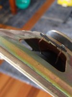
As I've modelled and built 6th's well in the past I was hoping to model conventionally with the rear section firing forward (thus eliminating a mid chamber). Unfortunately after building the rear section it appears that am short 1" in terms of clearance to close the trunk, thus I have to lay the rear section flat and have the drivers firing downward which introduces some interesting considerations of having a mid-chamber (I guess turning this enclosure into technically an 8th order).

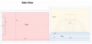
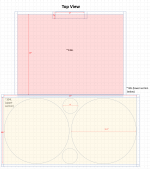
In nutshell, this system comprises of three sections in order to fit inside the trunk (will be sealed together using foam gaskets so they can be easily disassembled). The images I put together PPT below show the general configuration. The side-view I think most clearly shows the geometry of what I am dealing with.

attachment.php


attachment.php


(All values below are net after displacements, wood thickness is 0.75" MDF)
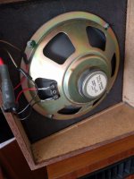
- Rear (yellow): ~104L: houses two B&C 18SW115s, two 22cm 4"ID PVCs, when considered standalone tunes to ~38Hz. The drivers are recessed in this chamber by 0.75" for speaker protection.
- Mid (blue): ~42L: a chamber with an open-top that serves a "pedestal" for which the rear chamber to fire into. In essence, the foot-print of this chamber is identical of the rear chamber that is mounted atop of it. The front of this chamber has an opening to where it mates to the front chamber; the opening here will be ~3"x29.5". This chamber is the crux of the problem as it has an effective axial area of ~895cm^2 (3.75"x37") over a length of 47cm which then steps into to front chamber having an aperture of 571cm^2 (3"*29.5").
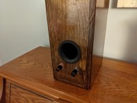
- Front (red): ~136L: this chamber sleeves the inside portion of the trunk and mates up to the ski pass (~489cm^2 of port, ~2" in length but this can be adjusted as needed). From the top, the front chamber is slightly narrower than the rear/mid chambers.

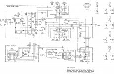
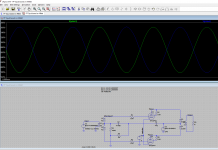
Modeling is done in Hornresp, with 1kW of power, using semi-inductance parameters I've derived from the impedance curve. The volume of each section is quite trivial (~286L total in each model) but it seems that the geometry (in terms of length/areas) results in significant deviations from model to model. I would appreciate any advice on what would be most appropriate. The problem at hand is that I don't think I can bin the mid and front chambers and consider them simply in terms of volume as I think there are some compression effects happening in the mid-chamber.

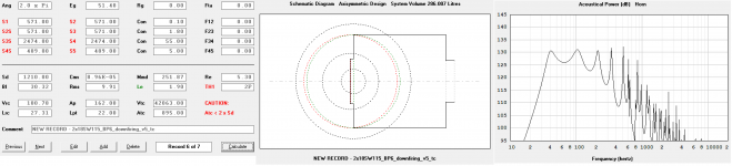
Model 1: TH1 using a standard rear chamber, mid-chamber is approximated ~895cm^2 using two horn sections (this not account for the step change into a 29.5"*3" (571cm^2) aperture into the front chamber.
attachment.php


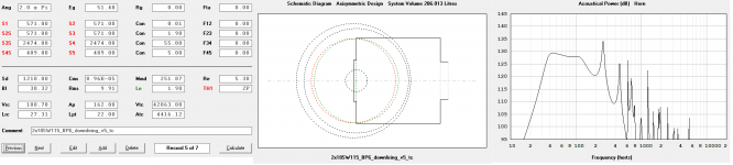
Model 2.1: TH1 using a standard rear chamber, mid-chamber is accounted for in Vtc/Atc; Atc is 4416cm^2 giving a length of 9.52cm, this loads into the front chamber through the 29.5"*3" aperture into the front chamber which is accounted for here
attachment.php


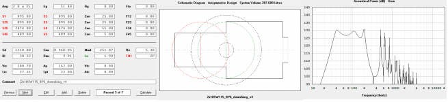
Model 2.2: TH1 using a standard rear chamber, mid-chamber is accounted for in Vtc/Atc; Atc is 895cm^2 giving a length of 47cm, this loads into the front chamber through the 29.5"*3" aperture into the front chamber which is accounted for here
attachment.php


There are a couple critical questions in regards to the models:
- Models 2.1 and 2.2 are quite similar with the difference being the consideration of the "length" of the chamber relative to everything else. Is it seen as 9.52cm (height) or 47cm long (length). I like these in that they both consider loading into the front chamber through the step change in the mid chamber but are quite different due to the considered length of the mid-chamber? What is most appropriate? Or maybe something in the middle, like a 24cm approximation of length.
- What is the most "correct" placement of the front and rear entry points? Effectively, I would like to have woofers and port as a single point loading in at 25cm (the center point of mid-chamber) but I don't think that it's possible to do with more segments, which I don't believe Hornresp supports. Given horn-resps constrains it seems that the driver and vents are offset by some distance which results in model differences between the two.

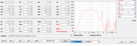
Model 3: BP8 Wizard where the mid-chamber step is considered as a 0.75" port of area 571cm^2. I think this one is the most ambiguous of what is happening in terms of geometry.
attachment.php


All in all, I think the responses in all models looks fairly workable in the frequency band I want to target but it would be nice to have a relatively flat response with slight emphasis at 40Hz (which model 2.1 presents).

As always, I would be very greatful for any advice and insights on this design.

Attachments

  • 1_sideview.PNG
    1_sideview.PNG
    107.9 KB · Views: 270
  • 2_topview.PNG
    2_topview.PNG
    72.2 KB · Views: 243
  • mod2_1.png
    mod2_1.png
    52 KB · Views: 248
  • mod2_2.png
    mod2_2.png
    55.8 KB · Views: 250
  • mod3.png
    mod3.png
    44.2 KB · Views: 231
  • mod1.png
    mod1.png
    54.7 KB · Views: 229

Successful TU-8600S Project

Victor,

I would like to thank you for your encouragement and advice, both in making an informed purchase decision, and during the construction of my new TU-8600S amplifier.

I was pretty hesitant going in, but I jumped in with both feet and never looked back. The packaging of the kit was excellent. The manual was amazing. The only way anything could have gone wrong was if I failed to follow directions.

After much lead bending, soldering, trimming, checking & rechecking, etc. I had a fully populated PCB. After comparing the completed PCB to the floorplan, I assembled the amp without covers, installed the tubes, plugged it in, and flipped the switch... No smoke!!! So far, so good. I then check all of the voltages and they were all within spec.

The last test was to hook up a pair of speakers. Music!!!

Again, I cannot thank you enough.

I will attach photos as soon as I have everything buttoned up.

I am looking forward to my next Elekit project with VK Music.

Sincerely,

Lew

Looking at Lii F12 - Box Dimensions?

Hello Everybody,

I'm looking at a pair of Lii Audio F12 fullrangers. I did a search here for Lii Audio but nothing came up. Anybody have experience with Lii and can speak to build and audio quality? Apparently they have made some inroads into the Decware and SET communities.

Based on these specs for the F12, could anybody give me some box sizes with front port size and length? Unfortunately they don't list Bl, Mms or Mmd, Le, or Vas.

Nominal impedance Z: 8Ohm
Power:40-80W
Frequency response:50-15khz
Fs: 32.8 Hz
Sd: 53.093m³
Qms: 14.629
Qes: 0.746
Qts: 0.710
Magnet:Y35(Ferrite)
Mean Sound Pressure Level: 94.8dB (2.83V/1m)
Weight: 11 KG
Package dimension: 42*36*36 cm
Paper Cone Material: Compound Pulp


Thanks a bunch!

Rebuilding My Buffered Volume Control

Q: I really like my buffered volume control (BVC) and it sounds great to me and the kind of music I enjoy listening to. So why am I planning to rebuild it?

A: Because it's there!

Not having any mountains to climb, at least for the present, I always wanted to say that. Now, to the specifics: My present set-up, which I use to listen to CD's and my FM tuner, consists of a dual 50K Alps pot driving one AD845 op amp per channel connected in non-inverting voltage follower mode. Very simple and basic but it seems to work very well.

First, I plan to replace the Alps pot with a 50K stepped attenuator. Probably 24-position unless a 47-position would be more useful?

Second and last, I want to build a remote power supply mounting the transformer and the rectifiers in a separate enclosure connected to the BVC enclosure with an umbilical cord thus removing all AC from the signal-carrying section. The separate power supply will house a 3-conductor line cord (grounded to the PS chassis), a SPST on-off switch, a fuse holder, an Avel-Lindberg 100VA, 18V transformer, 2 bridge rectifiers (one for each of the A-L two secondary circuits, with the diodes bridged by .01uF metallized polypropylene caps) and two 1000uF, 35V electrolytic caps at the output. The 1000uF caps will add to the 4700uF caps already in place on the PS board mounted next to the signal-carrying board in the BVC enclosure. The bridge rectifiers and bypass caps will be removed from the PS board as they will no longer be needed.

BTW, the PS board was designed by Grayson King and I populated it with all the components that he recommended so I'm sure it's of the highest quality. I obtained it from the days of Audio Amateur magazine when they use to sell a great variety of materials for the DIYer. I also have his board for the preamp he designed but have not used it because I only wanted a simple buffer whereas the King board provides gain. How I loved that magazine!

A couple of questions I can think of off the bat: I'm using a star ground system in my BVC enclosure where the power supply board is also grounded. Should I also ground the PS to the remote PS enclosure where the line cord is grounded or avoid that connection?

Finally, would it be worthwhile to employ a SS relay for turn-on or would it be unnecessary or overkill? I was thinking of the Crydom A1210 for example which turns on at zero crossing. Whether or not I use it will also determine the dimensions of the separate PS enclosure I will need and as I'm in the process of gathering the parts I need construction will take a little time.

Thanks to all who read this as while I enjoy building relatively simple audio projects admittedly I am a rank amateur in the field of audio. I would certainly appreciate any suggestions one might have.

FS: Summa speaker pair (NS15)

I'm selling these wonderful speakers, even these are the best in my audio life. These where bought new from Earl in 2014, and I've used it for about two years.
I moved from the place (pictures at Earl's forum) I had taken pictures in 2014. In my new house, I' can't find a place where it sounds right, as the acoustic is terrible (even these speakers are good with small rooms). I've tried almost everything (and of course Earl's recipes). As I won't move in a near future ... and headhones are not bad at all.
As it costs something sending it, it could interest someone in Europe.
I can also sell together, but this is optional, all the stuff to make this Summa work:
- miniDSP 4x10 HD and / or NanoDigi 2x8
- two Rythmik subwoofers
- digital amplifiers (diy) and / or gainclones (diy)
- one Allo player with Digione
I'll send new pictures to the ones interested and answer the questions.
Alain

IR4301

This module is marketed as super efficient (even at lower output powers) not requiring a heat sink for 100W output. Whats interesting for me is that the operating voltage is high (80V abs max) and the thermal resistance to the case isn't that high (4C/W). I'm thinking with a bit of heatsinking and a multilayer board with thermal vias for real world signal crest factors in excess of 6dB this amplifier could be bridged into 4 ohms loads and not overheat.

This is an app note where a small heatsink is applied and continuous ratings of 130W achieved and also peak power up to 220W with a heatsink:
https://www.infineon.com/dgdl/iraudamp12.pdf?fileId=5546d462533600a401535697359c2bdd

I guess what would stop this working would be if the chip started to limit output current and/or some other mechanism caused high distortion. The datasheet does have an over current protection block shown in the block diagram which is set to 16A limiting peak power to ~500W.

Seems to be a lot of advantages for the usual TI parts and I can't find any DIY discussion.

Anyway thoughts?

Arguments against "super tweeters"

They were all the rage a few decades ago, and a few still sold, but I was wondering looking at the need to move to a 1 1/8 tweeter to get the crossover low enough for a 6 inch mid/bass, but top end issues and excessive stored energy make it a less than an optimal option. What are the drawbacks from the larger tweeter, and then slap something with a great top end, even a little XT-25G on it for 10K up? First order crossover even.

I would rather a really great midrange that could get up to 4K where you could use one of several decent 3/4 tweeters, but they seem to be in short supply or their efficiency is so low, you would have to bi-amp.

How do I use both FIR and IIR filters in NAJDA setup?

I read in the main NAJDA thread that it's possible to utilise both FIR and IIR filters in the same setup, using IIR crossovers on the outputs, then adding a FIR filter on the inputs to align the phase.
However, only the FIR filter setup allows you to load filters on the inputs. So how does one go about specifying IIR filters on the outputs in the FIR setup section? Is it simply a matter of loading IIR coefficients instead of FIR? Or is there something I'm missing?

suggested crossover point?

HAPPY NEW YEAR!!!

I could use some advice please...

I have a pair of radian 475 PB-8 compression drivers in Altec 511B ( I think ) or 811B horns, atop a JBL AL6115. Not sure if this is a great match....

Radian says the lowest recommended x-over freq is 1.2 K, but fails to mention the slope.

Since this is for home use, so it will likely only ever see 1 watt or less of power... maybe 2 if I'm nuts.

Would the Radian 324/1594 be a decent crossover to use in this installation? ( 1.25KHz crossover frequency ).It is 12 db per octave.

Radian says: NEW 2-Way 1.25kHz Crossover

Phase, Frequency, Time Delay & Volume Compensation
For Use w/ A 8 Ohm High Frequency Driver & 8 Ohm Woofer
Time Aligned For Use w/ A 90°x 40° Horn <- this looks ok

Any help here would be most appreciated!

3-Way Active XOver w/ MiniDSP 2x4 and OpAmp

Hello all,

First off, I just want to warn that I am in school for mechanical engineering and have only taken enough electrical classes to get myself into trouble. That said, I am trying to design a 3-way active crossover to use for a stereo set of Econowave speakers I am building (I know, late to the party...) as well as a single subwoofer. I have a MiniDSP 2x4, and plan to use 2 of the outputs for the compression drivers exclusively. The other two channels will be the L/R output for both the mids and subwoofer content.

I am in the process of designing an op amp based circuit to further split the mid/low content between the woofers and sub, crossed at 100 Hz. Following the information on the Linkwitz site, I think I need 4 circuits per channel: a buffer, a high pass to the woofers, a low pass to the sub, and some sort of phase correction on one of the channels (absolute phase can be corrected in the DSP). I have implemented the first three circuits using a generic op amp in LTSpice, with the schematic as well as frequency and phase response attached.

Note that the high pass is an LR2 circuit, while the low pass is an LR4. I chose this because the woofer already exhibits a rolloff below 200 Hz, and I think using a 4th order high pass might result in too deep of a null in the crossover range.

It seems like the circuit is doing everything it should, however I have a few questions to finalize the design which I would appreciate some expert insight on.

1) There seems to be a 90* phase offset between the high and low pass. Does this seem right? If so, is there an all-pass circuit that I could use to correct a 90* phase offset? The Linkwitz web site only lays out circuits which result in a phase change of 180*. Or, would it be better to use an LR4 crossover for both circuits so that they have equal phase change, and then correct phase and any equalization issues with the DSP?

2) I designed this as an op amp circuit, particularly with the OPA2134 in mind, which seems to be a favorite on the board. However, I am in no way an expert on component choice and am not even married to the idea of using op amps. I have seen the JFET (?) topologies used in the Pass active x-over board and would be interested in that as well, but am less sure on what the schematic should look like. Does anyone have any input on using op amps vs discrete transistors, or component choice in general?

3) There will be a big difference in efficiency between the woofer and sub. I remember from an electrical class that op amps can be set to have a gain; would incorporating an additional gain circuit on the sub output be a good way to make up for this level difference? Or perhaps a simple class A pre-amp circuit?

Any insight on any of these questions would be most appreciated. Thank you!

Attachments

  • ActiveXOver.PNG
    ActiveXOver.PNG
    34.3 KB · Views: 279
  • ActiveXOverResp.PNG
    ActiveXOverResp.PNG
    23.2 KB · Views: 266

AMBER series 70 not ambling!

I have an Amber series 70 with what seems to be defective LM391N-100 chips in both channels. I have 'Fluke meter' checked every diode, the drivers, and outputs and all test OK in circuit.
I am considering taking a chance on a 'off shore' source for the chip but would appreciate ideas on the best source. Also any other tests that could be performed before inserting the new chips?
The Amp powers up and fuses hold with driver boards installed and chips removed. One of the chips will smoke the two 68 ohm series resistors to pins 15 and 16. The other chip does not burn these resistors but send the speaker output to +38 VDC.

Attachments

  • DSCN2023.jpg
    DSCN2023.jpg
    969.2 KB · Views: 161

46 TONG-SOL new tubes

SOLD 46 TONG-SOL new tubes

SOLD SOLD I broke the seal on one of these myself. Tested on a Hickok TV7-U
50 is low . black plates , hanging filaments , nice boxes , made in the 30's
Tube test 102 and 97 . New tubes would make a nice amp.
80$ per pair

Attachments

  • IMG_1534.jpg
    IMG_1534.jpg
    792.2 KB · Views: 468
  • IMG_1531.jpg
    IMG_1531.jpg
    940 KB · Views: 461
  • IMG_1533.jpg
    IMG_1533.jpg
    896.9 KB · Views: 433
  • IMG_1532.jpg
    IMG_1532.jpg
    863.6 KB · Views: 421

NAD 4020 Display Lamp Replacement

Hello -
I have an NAD 4020 tuner and the display light has gone out. Would anyone happen to know what value the bulb is and if it's still available (source for replacement)?

Anyone replace with LED? As the current bulb appears to be to one side of the display I'm wondering if it would still light the full display as the bulb does today. (I'm assuming the LED has less lit surface area to shine on the display.)

Thanks,
Comsat

Paradise Pre Regulator complete Kit - first Group buy item

FS: Paradise Pre Regulator includes PCB components including transformer/rectifier/Chokes - Please contact me if you are interested. I have my original paypal mail with actual cost cost to me + shipping+Paypal
first come first serve- please PM me. Prefer US buyer as it is heavy and shipping will be reasonable for US buyer
thanks
kannan

Super Regulators

One pair of Super Regulator boards. The circuit is as published on Jan Didden's website. I opted to place both positive and negative regulators on the same board with a common ground, connected at the input. The sense inputs are hard-wired and not brought out to external pads. Voltage is set for 17.7V but, of course, can be changed easily with a single resistor swap.

Dimensions are 2 3/4" x 3".

These are prototypes I built in November using all new parts. They are in perfect shape and are very lightly used. The only issue is a layout error on the LM329 references; to fix, I had to cut unused pin 1 off the TO-92 devices and mount on the remaining two leads, which should not impact function or reliability.

I've built more of these (with corrected layout) and they've worked first time and show no signs of instability.

I am also offering two unpopulated PC boards (also corrected) for a complete dual-mono power supply.

My actual parts cost for the individual regulators is $50, which is my asking price. I'm asking $10 each for the bare boards. Buyer pays shipping.

Please note: I guarantee the regulators will be in working condition on shipment. For the bare boards, I will provide technical support within reason; but the buyer should have experience with high-gain circuits and SMD soldering. Please do not bother Mr. Didden with issues related to my layout. Out of respect for the original designers, I will not be releasing the design files.

Attachments

  • reg1.jpg
    reg1.jpg
    494.6 KB · Views: 261
  • reg2.jpg
    reg2.jpg
    409.7 KB · Views: 254
  • reg3.jpg
    reg3.jpg
    748.3 KB · Views: 259
  • reg4.PNG
    reg4.PNG
    129 KB · Views: 277
  • reg5.jpg
    reg5.jpg
    795.4 KB · Views: 270
  • DCG3 Power Supply.jpeg
    DCG3 Power Supply.jpeg
    348.7 KB · Views: 204

First timer : balanced binding posts

Hey everyone, this community is awesome. I'm learning a ton reading through the forums. One thing I haven't come across yet, is how to handle soldering two "output" wires to one binding post terminal. I've scoured the web, looking for videos or walkthroughs documenting how to handle the situation, but haven't found anything and am admittedly clueless. I'm attempting my first ever soldering with my first ever amp build on the 500ASP, with ghentaudio GK-ASP-MX case kit. I have one xlr input and a single pair of binding post outputs. The wiring harness that comes with the GK-ASP-MX has a jst signal cable with two red wires and two black wires. I'm assuming that I just solder both black wires to the black terminal and both red wires to the red terminal, but I don't want to fry my board or my house 🙂 If this is the method, what's the benefit of two wires per terminal (I see most builds online to only have one per terminal)? Is this required for "balanced" output? It seems that if you munge it all together in the same terminal, you're providing the same thing as one, maybe fatter wire, but I'm sure I'm missing something.

Thank you!

Robbie

TPS7A4901/TPS7A3001 low noise bipolar PSU PCBs

Hi,

I offer bare PCBs for a bipolar PSU based on the TPS7A4901/TPS7A3001 low noise LDO regulators. It is capable of up to +150mA/-200mA current supply at +33/-33 VDC. The absolute maximum supply voltage to the board is 25 VAC (each rail) or +36/-36 VDC. The board size is 3x8 cm, mounting holes are on the 10 mm grid (2x7cm center-to-center distance). The design is briefly documented here. The schematic and images of the bare and assembled boards are attached.

PCB is hand solderable. The only challenge is soldering the thermal pads of the regulator ICs. It requires strong soldering iron to conduct the heat through the vias from the underside to the thermal pads. Using hot air rework station significantly simplifies the assembly.

The estimated BOM at Mouser is around 38 Euro.

I also offer a new design board using DC-DC converter at the input (see post #10 for details and #11 for the BOM). The development thread is here. This board size is 3x7cm.

Price: 6 Euro/PCB (bare board, no parts)
Bipolar power splitter PCB: 2 Euro/PCB

Worldwide shipment: 2 Euro (ordinary mail) or 4 Euro (registered mail, traceable).
Payment by paypal.
PM if interested!

Regards,
Oleg

Attachments

  • LDO.Regulator.Schematic.png
    LDO.Regulator.Schematic.png
    20.2 KB · Views: 2,061
  • LDO.Regulator.Bare.jpg
    LDO.Regulator.Bare.jpg
    245.9 KB · Views: 2,200
  • LDO.Regulator.Assembled.Top.jpg
    LDO.Regulator.Assembled.Top.jpg
    225.6 KB · Views: 1,831
  • LDO.Regulator.Assembled.Bottom.jpg
    LDO.Regulator.Assembled.Bottom.jpg
    421.9 KB · Views: 1,801

Martin Logan Ascent speakers

I have owned two Martin Logan Ascent speakers for a number of years, and have recently noticed that the two electrostatic panels have slid down in their supports, in one case severing the three connecting wires, blue black and red. It is clear that the blue wire has to be soldered to the front of the panel, and the black wire to the back of the panel. I can't see how to reattach the red wire. Ih has a small strip of copper tape attached to it (see attached photo). It may be that the copper tape goes all the way around the edges of the panel, in which case it may be impossible to reattach the wire. I live in Belgium where there is no Martin Logan dealer, so any advice you can give me would be most appreciated.

Attachments

  • IMG_0101.jpg
    IMG_0101.jpg
    485.7 KB · Views: 91

best drum solo or recording?

Why should the guitarists be the only one recognized? Let's hear about your favorite drummer, drum solo, or outstanding drum recordings...

Favorite solo: Dave Weckl and Steve Gadd- title track to Weckl's cd "Master Plan". Both drummers playing on one track, alternating solos, panned slightly left and right. Not the best recording- completely overproduced, as are most of Dave's recordings, but great playing.
:snare:

Anything by Vinnie Colaiuta...

NS :zombie:

First Port Resonance Too Low?

I am coming up with a large ported home theater subwoofer enclosure design. The goal is a low tune with minimal port noise. But with a port that is large enough to keep port air velocity low, I am now getting a calculated first port resonance of 87Hz in WinISD.

I can of course get it over 100Hz if i make the port slightly undersized or make the internal chamber oversized. But is a 100Hz port resonance still a big problem?
How much do i have to worry about port resonance?

Novice build of a 9.2 system

I hope this is the right place to post, I'm an amateur woodworker but no experience of diy audio. I ordered 4 of the Dayton Audio BR-1 component kits and the components for a TriTrix MTM to act as a centre. I'll probably build a par of subs next year. I also plan to make stands for all the bookshelf speakers.

Progress will be slow as I am also renovating the room to be used as a home cinema, but I thought there might be some interest in the speaker build progress here.

Last night I managed to assemble three pairs of the crossovers. My soldering was acceptable after I found my iron that has been gathering dust for years. The hot glue work was messy but effective I think, as everything feels nice and secure.

PXL_20201002_154724882.jpgPXL_20201005_003552236.jpg

What, no New Years Thread yet?

I hope this doesn't offend the admins, and will be taken in the spirit of a new year:

May the road rise up to meet you.
May the wind be always at your back.
May the sun shine warm upon your face;
the rains fall soft upon your fields and until we meet again,
may God hold you in the palm of His hand.


I wish every one a Happy New Year and let's leave 2020 behind us.

Zappiti Pro HDR help?

I got one but I managed to break the 5v supply to the IR/remote circuits which with a f/w update has rendered the player useless. It would operate through network controls but with the update it will only "listen" to the remote control as part of finalizing the install.
I had 12 volt on the 5v supply so I am assuming the remote IC and support is fried.

Does anyone have an understanding of the circuits in these units and what IC I would need to change?

got 24 Telefunken E88CC... are they all good for the waste ?

Hello everyone,
I had the "opportunity" to get 24 Telefunken tubes, model E88CC. I'm pretty confident they are genuine, for reasons I won't mention here. I have a uTracer and tested all the tubes. I made two tests :

  • quick check, where I set heater at 6.3V, Ua = 90V, Ug = -1.3V, and verified the Ia, which should be a typical 15mA.
  • the curve tracing, where I'm able to measure the current in the two triodes at the same time, in function of Va and Vg. In fact the same as above but for multiple points.
So I measured all 24 tubes (left 3-5 minutes for heater to settle before taking measures).
From what I read, is that I should get the typical Ia around 15mA at its minimum, mostly between 100 and 110%. However, most tubes are in the range 70-85% for Ia.

Below an example for one E88CC, and I would like you to comment it. The question is, are all these tubes good for the waste recycling ? Or do I oversee something and I'm sitting on a "small fortune" ?

Code:
Telefunken E88CC 
  
SECTION 1 
  
Test conditions: 
Va  : 90 (V)                 Swing +/- 9 V (10%) 
Vg  : -1.3 (V)               Swing +/- 0.13 V (10%) 
  
Test results: 
Ia  : 11.41 (mA)             76 % of nominal 15 (mA)              
Ra  : 3.05 (kohm)            117 % of nominal 2.6 (kohm)        Ra = dVa/dIa 
Gm  : 9.92 (mA/V)            79 % of nominal 12.5 (mA)          Gm = dIa/dVg 
mu  : 30 (-)                 92 % of nominal 33 (-)             mu = Gm*Ra 
  
  
SECTION 2 
  
Test conditions: 
Va  : 90 (V)                 Swing +/- 9 V (10%) 
Vg  : -1.3 (V)               Swing +/- 0.13 V (10%) 
  
Test results: 
Ia  : 11.19 (mA)             75 % of nominal 15 (mA)              
Ra  : 3.15 (kohm)            121 % of nominal 2.6 (kohm)        Ra = dVa/dIa 
Gm  : 10.5 (mA/V)            84 % of nominal 12.5 (mA/V)        Gm = dIa/dVg 
mu  : 33 (-)                 100 % of nominal 33 (-)            mu = Gm*Ra
attachment.php

Attachments

  • e88_plot.png
    e88_plot.png
    5.2 KB · Views: 854

"SB acoustics sb34nrx75-16" new driver designed specifically for open baffles?

"SB acoustics sb34nrx75-16" new driver designed specifically for open baffles?

A few hours after sending questions on this forum about fullrange speaker candidates suitable for open baffle systems, and very pleased with Dave's reply,

I found another open baffle candidate on the website of a professional speaker manufacturer who had long known in foreign countries.

SB Acoustics is a subsidiary of "SINAR BAJA ELECTRIC Indonesia" together with Danish, a Danish citizen, reportedly is the best former designer in Scan Speak. he is Frank Nielsen, I don't know him, I don't know much.

Recently they have included a list of new drivers claimed to have been designed specifically for the open baffle system on their website ,.

My question is; is there anyone on this forum who uses and opens an open baffle with this driver? Is this driver eligible to be filled in a shopping list or not? I hope to get a pleasant answer from this forum ,. 🙂 Thank you..

SB Acoustics :: 12” SB34NRX75-16

2 tube PP compact mono?

Hi - I was just wondering if anyone had produced a compact PP amp using two tubes. That is a single double-triode to perform pre-amp and phase split and a double power pentode (such as 6DZ7) as a PP driver?

If so, I guess quite a compact stereo PP could be made with just 4 tubes assuming SS rectification.

They say curiosity killed the cat, but I don't have a cat so it's worth the risk...
Projects by fanatics, for fanatics
Get answers and advice for everyone wanting to learn the art of audio.
Join the Community
507,774
Members
7,888,012
Messages

Filter

Forum Statistics

Threads
406,214
Messages
7,888,012
Members
507,774
Latest member
pete2000