Hello all,
First off, I just want to warn that I am in school for mechanical engineering and have only taken enough electrical classes to get myself into trouble. That said, I am trying to design a 3-way active crossover to use for a stereo set of Econowave speakers I am building (I know, late to the party...) as well as a single subwoofer. I have a MiniDSP 2x4, and plan to use 2 of the outputs for the compression drivers exclusively. The other two channels will be the L/R output for both the mids and subwoofer content.
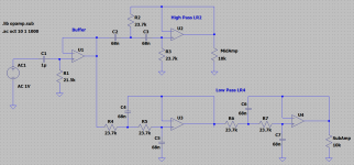
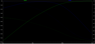
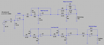
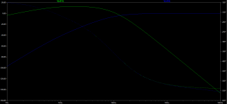
I am in the process of designing an op amp based circuit to further split the mid/low content between the woofers and sub, crossed at 100 Hz. Following the information on the Linkwitz site, I think I need 4 circuits per channel: a buffer, a high pass to the woofers, a low pass to the sub, and some sort of phase correction on one of the channels (absolute phase can be corrected in the DSP). I have implemented the first three circuits using a generic op amp in LTSpice, with the schematic as well as frequency and phase response attached.
Note that the high pass is an LR2 circuit, while the low pass is an LR4. I chose this because the woofer already exhibits a rolloff below 200 Hz, and I think using a 4th order high pass might result in too deep of a null in the crossover range.
It seems like the circuit is doing everything it should, however I have a few questions to finalize the design which I would appreciate some expert insight on.
1) There seems to be a 90* phase offset between the high and low pass. Does this seem right? If so, is there an all-pass circuit that I could use to correct a 90* phase offset? The Linkwitz web site only lays out circuits which result in a phase change of 180*. Or, would it be better to use an LR4 crossover for both circuits so that they have equal phase change, and then correct phase and any equalization issues with the DSP?
2) I designed this as an op amp circuit, particularly with the OPA2134 in mind, which seems to be a favorite on the board. However, I am in no way an expert on component choice and am not even married to the idea of using op amps. I have seen the JFET (?) topologies used in the Pass active x-over board and would be interested in that as well, but am less sure on what the schematic should look like. Does anyone have any input on using op amps vs discrete transistors, or component choice in general?
3) There will be a big difference in efficiency between the woofer and sub. I remember from an electrical class that op amps can be set to have a gain; would incorporating an additional gain circuit on the sub output be a good way to make up for this level difference? Or perhaps a simple class A pre-amp circuit?
Any insight on any of these questions would be most appreciated. Thank you!
First off, I just want to warn that I am in school for mechanical engineering and have only taken enough electrical classes to get myself into trouble. That said, I am trying to design a 3-way active crossover to use for a stereo set of Econowave speakers I am building (I know, late to the party...) as well as a single subwoofer. I have a MiniDSP 2x4, and plan to use 2 of the outputs for the compression drivers exclusively. The other two channels will be the L/R output for both the mids and subwoofer content.
I am in the process of designing an op amp based circuit to further split the mid/low content between the woofers and sub, crossed at 100 Hz. Following the information on the Linkwitz site, I think I need 4 circuits per channel: a buffer, a high pass to the woofers, a low pass to the sub, and some sort of phase correction on one of the channels (absolute phase can be corrected in the DSP). I have implemented the first three circuits using a generic op amp in LTSpice, with the schematic as well as frequency and phase response attached.
Note that the high pass is an LR2 circuit, while the low pass is an LR4. I chose this because the woofer already exhibits a rolloff below 200 Hz, and I think using a 4th order high pass might result in too deep of a null in the crossover range.
It seems like the circuit is doing everything it should, however I have a few questions to finalize the design which I would appreciate some expert insight on.
1) There seems to be a 90* phase offset between the high and low pass. Does this seem right? If so, is there an all-pass circuit that I could use to correct a 90* phase offset? The Linkwitz web site only lays out circuits which result in a phase change of 180*. Or, would it be better to use an LR4 crossover for both circuits so that they have equal phase change, and then correct phase and any equalization issues with the DSP?
2) I designed this as an op amp circuit, particularly with the OPA2134 in mind, which seems to be a favorite on the board. However, I am in no way an expert on component choice and am not even married to the idea of using op amps. I have seen the JFET (?) topologies used in the Pass active x-over board and would be interested in that as well, but am less sure on what the schematic should look like. Does anyone have any input on using op amps vs discrete transistors, or component choice in general?
3) There will be a big difference in efficiency between the woofer and sub. I remember from an electrical class that op amps can be set to have a gain; would incorporating an additional gain circuit on the sub output be a good way to make up for this level difference? Or perhaps a simple class A pre-amp circuit?
Any insight on any of these questions would be most appreciated. Thank you!
Attachments
First off, I have nothing to contribute except for for the fact that I am a mechanical engineering student too and have taken NO classes in electrical engineering, and instead have been working on something similar as you.
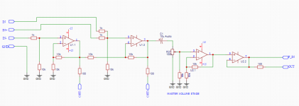
I've pieced together a Linkwitz-Riley filter module with balanced input option and onboard power supply and muting.
I can send you the gerber files should you be interested.
I've pieced together a Linkwitz-Riley filter module with balanced input option and onboard power supply and muting.
I can send you the gerber files should you be interested.
Attachments


One thing to consider is that if you don´t know what filter slopes will work for you exactly you should design your circuit in a way that it will be somewhat "flexible".
Ideal in comparison would be if you setup your system with a minidsp 2x8, setup, measure, correct, measure, etc.
Then and only then you know exactly which filter slopes you need.
Alternatively design your filter so you can realize 6/12/18/24-db/oct. filter.
Linkwitz-Riley-filter sound cool in theory but your drivers might be easier to play together in harmony with a butterworth-filter or ...
For a mono? subwoofer as it sounds you will want to sum L+R before the filter. (google 2.1 crossover to get you going)
I guess everything else can be corrected in the minidsp if needed (baffle step, notches, tweeter delay, etc.)
First off, I have nothing to contribute except for for the fact that I am a mechanical engineering student too and have taken NO classes in electrical engineering, and instead have been working on something similar as you.
I've pieced together a Linkwitz-Riley filter module with balanced input option and onboard power supply and muting.
I can send you the gerber files should you be interested.
Thanks for the offer. If I am reading the schematics right, the board is a 2 channel hi/low pass with volume control and muting? Have you built and tested the circuit to see if it operates as desired? Also, what active device are you using / do you have a BOM? Thanks!
One thing to consider is that if you don´t know what filter slopes will work for you exactly you should design your circuit in a way that it will be somewhat "flexible".
Ideal in comparison would be if you setup your system with a minidsp 2x8, setup, measure, correct, measure, etc.
Then and only then you know exactly which filter slopes you need.
Alternatively design your filter so you can realize 6/12/18/24-db/oct. filter.
Linkwitz-Riley-filter sound cool in theory but your drivers might be easier to play together in harmony with a butterworth-filter or ...
For a mono? subwoofer as it sounds you will want to sum L+R before the filter. (google 2.1 crossover to get you going)
I guess everything else can be corrected in the minidsp if needed (baffle step, notches, tweeter delay, etc.)
While I agree that a MiniDSP 2x8 would be the best route, I don't think that will be in the budget for a while yet. Since I already have a 2x4, I can take care of a lot of room eq, baffle step, etc as you mentioned, I just need to figure out how to effectively split out the sub signal. You are correct that the sub will be mono for now, but I would like to design it as a stereo sub circuit with a mono switch. I will google the 2.1 crossover to get an idea of what's involved.
Is there an active topology for Butterworth XO, or would that need to be a passive circuit? Also, is there a particular reason you think the drivers might sound better with this topology?
Thanks for the offer. If I am reading the schematics right, the board is a 2 channel hi/low pass with volume control and muting? Have you built and tested the circuit to see if it operates as desired? Also, what active device are you using / do you have a BOM? Thanks!
You are correct. It can also be configured as a bandpass with some small modifications. For a 3-way crossover I plan of using a 2nd pcb stacked on top of the first with just the filter components installed.
To be clear, I have ordered the pcb's but have not yet tested them whatsoever. If don't think this will be my definite design either as I probably will make some changes after testing. But it might give you some inspiration should you decide to build your own active crossover
Back in my collage days one of my roommates was an ME. I was an EE. I spent some of my time trying to help him through his required circuits courses. Those things were brutal - they basically compressed into a single semester what we would normally cover in three.
Whatever power amp you use for the sub (and the other channels for that matter) should have someway to manually adjust the gain. I would use this rather than try and add additional stages to the filter.
Here are a couple good reference pages:
* Sallen-Key filters: Sallen–Key topology - Wikipedia
* LR crossover project: Linkwitz-Riley Electronic Crossover
Hello all,
3) There will be a big difference in efficiency between the woofer and sub. I remember from an electrical class that op amps can be set to have a gain; would incorporating an additional gain circuit on the sub output be a good way to make up for this level difference? Or perhaps a simple class A pre-amp circuit?
Whatever power amp you use for the sub (and the other channels for that matter) should have someway to manually adjust the gain. I would use this rather than try and add additional stages to the filter.
Here are a couple good reference pages:
* Sallen-Key filters: Sallen–Key topology - Wikipedia
* LR crossover project: Linkwitz-Riley Electronic Crossover
You are correct. It can also be configured as a bandpass with some small modifications. For a 3-way crossover I plan of using a 2nd pcb stacked on top of the first with just the filter components installed.
To be clear, I have ordered the pcb's but have not yet tested them whatsoever. If don't think this will be my definite design either as I probably will make some changes after testing. But it might give you some inspiration should you decide to build your own active crossover
I see. I do like the idea of the built-in power supply, I was browsing the internet trying to figure out how I wanted to implement that. Are op amps particularly sensitive to noise on the power inputs?
Back in my collage days one of my roommates was an ME. I was an EE. I spent some of my time trying to help him through his required circuits courses. Those things were brutal - they basically compressed into a single semester what we would normally cover in three.
Whatever power amp you use for the sub (and the other channels for that matter) should have someway to manually adjust the gain. I would use this rather than try and add additional stages to the filter.
Here are a couple good reference pages:
* Sallen-Key filters: Sallen–Key topology - Wikipedia
* LR crossover project: Linkwitz-Riley Electronic Crossover
My circuits professor was excellent, so I ended up enjoying the course and learning a lot. However I ended up taking a few more classes in E&M theory and was not quite as excited about those...
The second link mentions using a gain stage as a final circuit to drive the power amp. Is there a particular reason you advised against this? For the sub, I was probably going to use a pro (Crown XLS series) amp, which has a 2V sensitivity, which I think will exacerbate the sub already being much less sensitive than the mains. Perhaps using a static gain stage on the crossover, then fine tuning with the power amp gain would be a good compromise?
Regarding the Sallen-Key topology - it looks similar to the LR circuit, unless I am missing something?
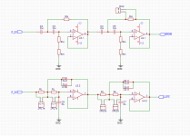
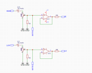
I added a phase correction to the woofer output, and a gain stage (5x) to the sub output. Schematic and freq/phase response are attached. Will there be a noticeable degradation in sound quality using the op amp at this gain level, using a normal audio op amp like the OPA2134?
Also, the phase of the woofer at the crossover frequency with the mids, 1.25 kHz, is about -520*. I understand that not correcting this will cause issues with frequency cancellation. However, does this also cause a time delay? I.e. will the woofer suffer from a time delay of:
-520*/360* / 1.25 kHz = 1.2 ms
If so, how significant is this number? I don't have enough DSP experience to know how much delay, is too much to fix with a computer.
Attachments
A suggestion from the wet-blanket end of the spectrum: why not just use anther MiniDSP?
I have considered that... For only $95 it might even be more economical than making a crossover, by the time I bought a power supply, case, etc.
Perhaps a stupid question, but would using two individual MiniDSPs result in any appreciable difference between the two in regards to timing?
It would be rather astonishing if it did. At the most you could be half a cycle out at 44.1KHz or whatever the sampling frequency is.
I have a 2x4 HD that I am using for a 2-way crossover. The EQ functions are quite good, though I have not use them a whole lot, other than in conjunction with REW. The FIR functions are way over my head.
Sorry, maybe that was not clear enough.While I agree that a MiniDSP 2x8 would be the best route, I don't think that will be in the budget for a while yet.
I wasn´t suggesting upgrading to a 2x8 but wanted to basically say, that you need to know your filter slopes before you design a PCB or make a flexible "clever" design.
Actually I was in the same shoes as you; that´s why I´m here;-)
A 2x4 for a open baffle 2-way which became a 3-way. Decided to do passive crossover on the tweeter/mid. (but that´s another can of worms..)
As you maybe know by now, the downside with minidsp or active systems in general is how to solve the volume control.
So if you wanna go ahead with your PCB do plan that in as well, maybe between or before the input buffers.
I like your frugal thinking (+learning a thing or two) but if you consider time and all, another minidsp would be the cheapest option.
In fact if you don't anther MiniDSP but an analogue filter you will have a much bigger delay problem between them.
Good point.
I´d be tempted to use a PCB (1) as input buffer, volume control and low pass for the woofers.
The PCB would have output buffer for the minidsp which would be dedicated to the compression drivers.
Problem with that solution is that you can´t filter the woofers for room resonances or the like which is very comfortable to do.
Of course you could add optional notch filters to the PCB.
Solution (2) would be as suggested by Kellis. For one of the compression drivers a delay could be realized on the PCB (optional).
Look at this crossover from TI (they do provide gerber files for that one!):
https://www.google.com/url?sa=t&rct=j&q=&esrc=s&source=web&cd=&cad=rja&uact=8&ved=2ahUKEwid266L4vftAhUpD2MBHdeHD8cQFjAAegQIBBAC&url=https%3A%2F%2Fwww.ti.com%2Flit%2Fug%2Ftidu035%2Ftidu035.pdf&usg=AOvVaw3sIVb0XjLJIdOLQ0TEO2Hg
- Home
- Source & Line
- Analog Line Level
- 3-Way Active XOver w/ MiniDSP 2x4 and OpAmp