chario silhouette 100 crossover recap?

Hi guys.
I got these Italian speakers for 150$. They are about 15 years old now (if I am not wrong).
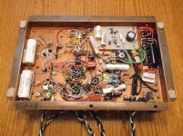
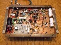
Box build is very sold and nice. Drivers are less nice as I understand.
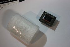
Woofer basket is made of plastic 🙂 Tweeter is really small thing, not impressive. Can post pictures if you want.
I am trying to get out of them the best they can give.

Currently they sound like some high frequencies are being played through woofer (some dull muddy sound) and not through tweeter as they should. I connected tweeter from other speaker and got the same result. I get such sound on both speakers, not on only one.

I don't think these Chario guys released such sounding speakers to market, so I guess there is some problem with them and problem is located in crossovers.

As I know first thing I can do is just go and recap them both. Sounds like a simple job for some of you, but not to beginner like me 🙂

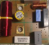
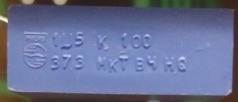
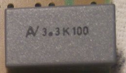
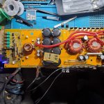
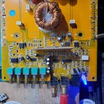
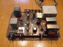
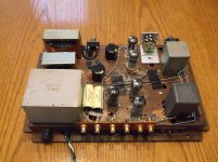
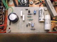
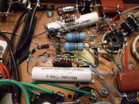
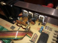
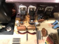
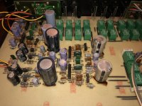
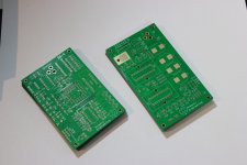
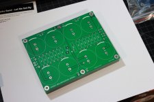
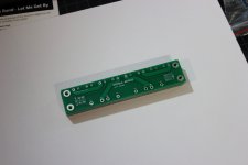
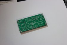
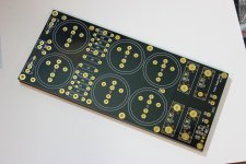
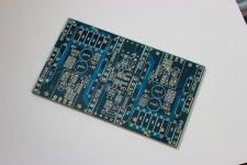
I took crossovers out without a problem, but I am having troubles on identifying components and their values.

So I need to get:
1) List of capacitors with their values.
2) Any advises from you if I should use some better components then currently installed (almost generic) ones.

Thanks a lot!

------------------------------------------------------------------------------------------------------------------------------------------
Update to summarize the thread:
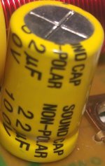
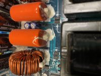
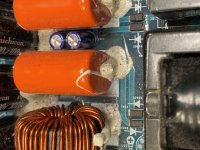
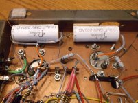
We decided not to touch any of capacitors except yellow one (bipolar electrolytic capacitor 22uf 100V).

Currently I replaced old yellow capacitors by ELNA RDB 100V 22uf bipolar right now.
Sound seems OK to me.
All modern low loss capacitors (MKP or electrolytic capacitors) are not relevant here.
They kill the bass and spoil mid range. We need to have high ESR electrolytic capacitor here (preferably old designs).

If someone is going to do such replacement for this speaker (or for other Chario), then please try to go with capacitors similar to
ELNA RDB (this is new model available to purchase):
https://hfc-fs.s3-eu-west-1.amazonaw...a_rbd_data.pdf
OR ELNA CERAFINE bipolar (old model which is not available to purchase):
http://www.elna-america.com/products/pdf_files/AL/ROA.pdf


Post updates here on your experience of replacements to any other kinds of capacitors. I will be glad to read.

Attachments

  • Clipboard01.jpg
    Clipboard01.jpg
    400.6 KB · Views: 432
  • Clipboard02.jpg
    Clipboard02.jpg
    398.7 KB · Views: 319
  • Clipboard04.jpg
    Clipboard04.jpg
    150.9 KB · Views: 290
  • Clipboard05.jpg
    Clipboard05.jpg
    163.6 KB · Views: 305
  • Clipboard06.jpg
    Clipboard06.jpg
    598.8 KB · Views: 324

NP-100v12 Build

I recently build a hybrid headphone amp from NP-100v12: DIY 12AU7 (ECC82) Tube / IRF510 MOSFET Headphone Amplifier .

Currently, I am combating a hissing noise that increase in volume as I turn the pot. I have built a LM317 regulator for it. I also have used an SMPS, but still have noise. The difference is, using the linear PSU the noise is a hissing noise which increase in volume as I turn my pot, while using the SMPS the noise is a constant humming noise.

The tubes in it is a 12AT7, which based on the original thread is compatible for this amp. What could be the problem in my build? Your help is appreciated

Also, can I use this amp as a preamp/buffer? If so, do I need to change something? Thanks!

Radio Shack Mini amp substitute

So the RS Mini amp has been MIA for years and only expensive old-stock on FleaBay... I mean $60 isn't going to break me, but then I came across this mini battery powered guitar amp sold at Guitar center for $23. Reviews seem good and I watched some videos on youtube about it.

Any comments on this thing as a suitable replacement for the old RS Mini Amp as a testing device for hobbiest amplifier service (Car audio amps)?

Honeytone N-10 Guitar Mini Amp Black | Guitar Center

8 years old electrolytic caps from DIGIKEY

A word of warning (especially if you have to pay taxes if you are not in the US) when buying electrolytic capacitors from DIGIKEY. I bought Nichicon capacitors with the date code B1311, this is March 2013, the capacitors are 8 years old now. After 3 years they start to deteriorate if they are not used. 8-year-old capacitors should be wasted and not sold as new.

I called DigiKey Europe's customer service and described the problem. I got the answer: why did you not ask what is the production date? What? Really? I should ask about the date of production of every electrolytic cap I am buying? This is very disappointing.

TS Pyramid PB-400a with STK4040XI

I got this Pyramid PB-400a which uses STK4040XI chips. Power Supply works when the rectifiers are pulled and outputs a healthy +40V. When the PS is connected, it oscillates on and off and a pulls heavy amount of current.

So question is, how do I troubleshoot whether the STKs are good or not?

If they are bad, I'm gonna send it back to the seller for refund, or at least try and get most my money back and see if I can find replacements.

TIA!
Tristan

Pro Audio line level interfacing to Home Audio line level: level and/or imp mismatch?

A typical and very common example would be using pro audio electronic crossovers, cheap and readily available, in home audio systems. Let's say, a pre-out in an integrated amp feeds a pro crossover, and the pro crossover then feeds home audio amps.

What troubles me is knowing that the pro electronic crossover is designed to work with stronger signal levels than the home audio gear. The crossover is expecting a stronger input signal than the home audio preamp can deliver. And the pro crossover is outputting a stronger signal than the home audio amp is designed to handle.


Below are comments relevant to my question, quoted from "Sound Reinforcement Handbook" 2nd Ed, 1989 by Gary Davis and Ralph Jones

"...line level phono jack inputs and outputs are intended for use with high impedance equipment, which is basically sensitive to voltage rather than power, so their nominal levels may be specified as -10dBV"

"Typical line level XLR connector inputs and outputs are intended for use with low or high impedance equipment. Since older low impedance equipment was sensitive to power, nominal levels were often specified as +4dBm or +8dBm, levels characteristic of sound reinforcement and recording..."

"A low impedance line output generally may be connected to higher impedance inputs without much change in level. Be aware that if a high impedance output is connected to a low impedance input, that output may be somewhat overloaded which can increase distortion and lower the signal level, and the frequency response may be adversely affected. In some cases, the equipment could be damaged....."

<end quote of Sound Reinforcement Handbook>


Would not connecting the pre-out of an integrated amp to the input of a pro electronic crossover be what is described in the last two sentences from the book, quoted in bold above?

Is using a pro electronic crossover with home audio amps and preamps, even though a common practice, less than ideal and potentially degrading sound?

FS: NEW CDA 120 Class D Audio Kit with Tranny

SOOOOOOOOOOOOOOOOOOOOOOLD!


I have a new CDA 120 Class D Audio kit. Boards in mylar bag and never used or molested. Antek tranny in box unused.

x1 CDA 120 amp board

x1 power supply board with beefier caps

x1 Antek tranny shipped from Class D Audio

Asking $75 and you pay actual shipping. Should fit in USPS Large Flat rate box at approximately $13. Please add 3% for PayPal. I'll take USPS money order as well.

Nick

new project: TD124 with the Papst motor

papst_1.jpg


After seeing Volken's page on cap tuning the Papst motor to work smoother in a TD124 I thought I'd give it a try. If the cap tuning doesn't quite get me where I want to be I'll resort to finding a 3-Phase motor controller and putting that to use.

But first I need to build up this TD124. SN 13943.
DSC_0512.jpg


The original paint on this unit was less than acceptable. So I decided to refinish it. First, I used Aircraft Remover to chemically strip the paint off. Aircraft Remover (yes it is the product name) is popular among automotive painters and also aviation painters. Good stuff.

More info here:
13943

-Steve

The Intellectual People Podcast - Mitch Barnett of Accurate Sound

Mitch Barnett of Accurate Sound tells us about his journey to become a leading expert in Digital Sound Processing (DSP). Accurate Sound is a remote service using Audiolense, Acourate and Room Eq Wizard (REW)

Accurate Sound Calibration using Digital Sound Processing (DSP)? | Mitch Barnett - YouTube

Attachments

  • Accurate Sound Thumbnail.jpg
    Accurate Sound Thumbnail.jpg
    257.1 KB · Views: 153

Isobaric ESL alternative

So just want to share my Eureka moment. Not much of a response on a thread I started about isobaric ESLs. I did not try it because of advisory info on another thread. But this is a bit different. I have a pair of Acoustat Monitor 3 with DD OTL monos. The panels are mounted on the back of the frame structure so there is a 1" set back/recess. I ordered 5/8" thick felt, same medium density as the strips on the backs already to tame resonance. So I cut and covered the entire front side of the panels with felt, filling the recess of each panel/frame recess. I then mounted a second set of panels on the front of the frame, sandwiching the felt. I did not remove the original felt strips on the backs of the second set. Guess what happened when I tapped on the front panels...Nothing! Dead, no resonance to speak of. How silly, right? But here's the trick.. I also hooked up a second set of DD OTLs!! So now there is full damping without loss of output. It's hard to describe just how much better they sound. There's no comparison. The rolled off top end character is gone, mid range is spectacular, that upper bass tubbiness is gone. Sound stage is far more enveloping/depth is just awesome. The sound is so close and intimate it's as if you're right up next to them. This is how they should have been designed in the first place. This tweak is anything but boring.


Just thought I'd mention it.🙂

Qu re: Tweeter LCR resonance compensation

I was looking at a VIFA application sheet for one of their old tweeters. It was very comprehensive and included a suggestion for an optional LCR network to place across the tweeter to compensate for the resonance (approx 1,500 c/s).
Now I understand that this will reduce the normal res' peak and allow the crossover to "see" a flatter impedance at the drive unit and so perform more closely to its theoretical design goals. It was the next bit that I didn't understand. The sheet goes on to say:

"The load provided by the cross over should be as low as possible at the tweeter resonance frequency. To ensure maximum electrical damping and consequently minimum excursion, it is also recommended to apply a parallel compensation circuit. This is essential for high power output."


So I am clear on its purpose in optimizing the cross over termination but not on how the network reduces the excursion.......
any thoughts would be appreciated.....

And a very "Merry Summer Solstice Situation"* to everyone.
Jonathan

* I am in the Southern hemisphere!

Aiwa an8745 turntable stuck on 45rpm

My Aiwa AP-2200 turntable is stuck on 45rpm.

I was playing a 33rpm record and had paused it (pressed down the up/down switch), and when I came back to play it again the record was spinning much faster than it should be. I took the record off and placed a 45rpm one on to see whether that played properly and it did. I then toggled the switch from 33rpm to 45rpm and the speed stayed the same. It's like for some reason the 33rpm setting is playing at 45rpm. I adjusted the fine-tuning rollers on both settings and the 33rpm one still controlled that side, so the switch still does something.

Any ideas?

ICEPOWER 1200AS2 GB... Need One More

Looking for a few people interested in the Icepower 1200 AS2. We have a couple of confirmations now but need just a few more. The price would be 425+ shipping from MN each. They come in lots of 7 so if anyone interested come on board. I have found fully fleshed out enclosures to complete from Ghent audio. I'll try to link. Also try to attach the datasheet for the 1200.

https://icepower.dk/support/#download-expand

ghentaudio --- DIY Stereo Case for ICEpower 1200AS/700AS

Supplied links, datasheets were too big

SE sounds like there is a lot of dust on the needle.

Hi, I am not sure when things went wrong but my SE with 45s now sounds very fuzzy. I decided to try a higher voltage than the 275v that it was running with a GZ34S rectifier. So I put in a diode rectifier but the B+ was then 330v so I went back to the GZ34S rectifier. It now sounds very fuzzy. What is strange is the B+ is up at 312V - it seems to have bumped up by 40V. Also the bias isn't very steady, and sometimes one bias goes to 0 while the other doubles. I didn't see any smoke and a quick check of the components didn't reveal anything fried. Any suggestions as to where I should look? Thanks! Henry

Choosing my next DAC (build?)

Hey everyone,

The wife and I just relocated to the EU. I brought my entire system with me except my DIY DAC (for various logistical reasons).

Now, I need to decide if I'm buying a new DAC or building it myself.

The DAC that I had was based on ANK's DAC. It had an ANK DAC board, a JLsounds USB input, and a tube output stage that was built by a friend of mine. The sound was wonderful, it was natural and dynamic - but it was far from perfect. I can certainly "live" with that sound, but ill be more than happy to get more. I would say that the R2R NOS sounds is definitely my style.

So, here are the options I was thinking about:

  • Not build anything and get a Denafrips DAC (probably their entry-level model)
  • Get an ANK Kit.
  • Build something "from scratch" based on the Soekris.

It's important to note - I have a very limited understanding of electronics. I can assemble anything, I can soldier well and my entire system is DIY (from speakers to tube amps to phono stage to turntable) - but it's only because I can follow the schematics.

In a perfect world, I guess I would have built a Soekris DAC with a tube output of some sort - but I'm concerned that the knowledge base on the Soekris is too technical for me.

So - what's you take here? I would love to get your input.

Thank you!
Tank out.

Western Electric 555 Fieldcoil power supply

Hello and thanks for any information on this topic you may have.

I am currently working on building a system around a pair of the Western Electric 555 drivers and I contacted Rod Coleman for help with the power supply for these. Unfortunately, I cannot find any information on the value of inductance of the field coil.

If anyone has access to one of these drivers, or better yet, already has determined this value, please let me know.

Thank you for your time!

HiFiSonix KX monoblocks

So I'm interested in building HiFiSonix's KX design, but I want to do something a little different and I'm hoping to get a little guidance on my options.

I want to turn them into monoblocks that I locate near the speakers that they are powering. I also want to run the power supplies in separate chassis.

the whole idea stemmed from my desire to build the base schematic, then make an additional mono one for a sub, but then I got to thinking why not make them all monoblocks, further signal separation should be somewhat beneficial or at the least not harmful.

The part I'm going to need a little help with is the power supplies. I'm sure I can just go with some off the shelf ones if I want, but I'm not sure what specs I need for them. I see that it's 26-28VDC or 35VDC in AAB mode, but at how many amps? I would like to build my own PSUs eventually but for now I want to get the amps built and working quickly and somewhat cheaply. Any advice?

Aperiodic vent scaling

This may be a daft question but I'm going to ask it anyway -

If you have a design for a woofer in an aperiodic box and then double the box size and add another woofer does the aperiodic vent work like a normal vent i.e. you just double the area (or have two of them) keeping the length the same (i.e. the thickness of the box wall) ? Plus within reason can I assume the vent shape is immaterial so long as the area is kept constant ?

By way of an example, take the Seas A26 - 28l volume with aperiodic vent 30mmx220mmx19mm (wood depth) with 12g of stuffing. If I use 2 woofers in a 56l box can I use either two ports the same dimensions or a single port 60mmx220mmx19mm (again keeping the filling density the same, 12g>24g).

Sorry, this may be basic but just wanting to understand how this works.

HDMI to I2S (for audio not transport) working but w/ noise.

Hi,

I am trying to use HDMI as input for my ADAU1701 so I can digitally process the audio without the problem of the DSP's internal ADC's.

I have the following:
-. 3E Audio ADAU1701
-. HDMI to I2S Aliexpress board
-. PCM5102 DAC with I2S input.

When I connect the HDMI to I2S directly to the PCM5102 DAC it works perfectly, and it sounds quite good, but when I connect the HDMI to I2S board to my DSP It gets a ton of noise and what I think it's jitter. Unusable.

I presume the problem is in the clocks, so I tried every configuration available in the Register Control on Sigma Studio, and most of them did not make a difference. Setting "Program Length" to 4x and unticking "Master Mode" in "Serial Output" made the sound better but still with noise and jitter.

So, what is the problem and how can I fix it (If possible)?

Maybe the HDMI 2 I2S board work as Master I2S, and the ADAU1701 only supports I2S input as SLAVE?

Or the fact that the clock in the HDMI to I2S board is a 24.00Mhz crystal and the 3E Audio ADAU1701 has a fixed PLL setting for 12.288Mhz?

IDK. Any Suggestion is welcomed as I am planning on getting and HDMI to I2S board with all 8 channels available, but first I want to make it work in stereo.

Cheers

UPDATE1: I just noted that the publication of the PCM5102 DAC has this note: "BCK and DATA marked inverse!When using pls make BCK as DATA , DATA as BCK". So, if in my board they are inverted (but I connected them w/o knowing this), and it does work OK with my HDMItoI2S, maybe this HDMItoI2S board also has the BCK and DATA flipped? I don't think so, but I will try it anyway.

UPDATE2: I don't think the cables are flipped, after thinking a little, when I connect the PCM5102 DAC to my DSP it works perfect, so it's a NO GO.

Attachments

  • Capture.JPG
    Capture.JPG
    97.3 KB · Views: 219
  • Capture2.JPG
    Capture2.JPG
    159.9 KB · Views: 265
  • Capture3.JPG
    Capture3.JPG
    135.3 KB · Views: 257
  • Capture4.JPG
    Capture4.JPG
    177.6 KB · Views: 202
  • Capture5.JPG
    Capture5.JPG
    138.9 KB · Views: 236
  • Capture6.JPG
    Capture6.JPG
    120.1 KB · Views: 135

CAB 1600.1D Chinese amplifier. Output Help please.

. Ok so I repair drive. Change out the sn74hc02's on the driver card along with the driver transistors 2n4401-03, voltage regulators are all perfect but the output mosfets still explode. I assume this has to do with the timing of the turning on and off of the high and low side transistors. What is responsible for this?

Attachments

  • 16143534727563366069066181483825.jpg
    16143534727563366069066181483825.jpg
    930 KB · Views: 113
  • 1614353497635572123284741273836.jpg
    1614353497635572123284741273836.jpg
    821.9 KB · Views: 72
  • 16143535323605963910464003199594.jpg
    16143535323605963910464003199594.jpg
    955.1 KB · Views: 77
  • 16143535552397847355259986286090.jpg
    16143535552397847355259986286090.jpg
    603.3 KB · Views: 70

Cone mod to improve directivity of a fullranger.

Hi,

To get full range out of a driver the following is/are typically employed to extend the highs

1) The center of the cone is decoupled at higher frequencies and the cone iis used in breakup mode
2) Stiff dustc cap is used to extend the highs
3) Secondary whizzer cone is used
4) Phase plug is used to break the narrow beam at high frequencies

However, most of the drivers dont seem to focus on achieving constant directivity and polar plots are rarely shown.

So, my question is, can a full range driver be modified as below to get constant directivity. The idea is simple, let the center radiate the highs and as frequency comes down into the mids, have a larger portion of the cone kick in, thereby maintain a constant wavelength to radiating area ratio. Use a 2mm-3mm layer of felt to achieve the damping. Four broad felts are shown in figure but more narrow ones may be needed in practice.

Can the damping be adjusted by trial and error and constant directivity achieved?

Thanks and Regards,
WA

Attachments

  • DampedDriver.jpg
    DampedDriver.jpg
    18 KB · Views: 229

Wire Roksan Kandy for 120v

I have a Roksan Kandy that is wired for 230, is it possible to configure it for 120 here in the US? Unfortunately I can't find a schematic.


Hoping it's a dual voltage transformer, there is an unused white coming off the transformer. The transformer is a Toroid, TI-67381A.


From what I understand it would be 2x 115v primaries that are currently wired in series, the white would be used to wire in parallel to get 115v with twice the amps (need larger fuse).


Can I test to see if this is correct?

Attachments

  • IMG_20210224_202817720.jpg
    IMG_20210224_202817720.jpg
    660.1 KB · Views: 164
  • IMG_20210224_202831922.jpg
    IMG_20210224_202831922.jpg
    658.5 KB · Views: 164
  • IMG_20210224_202844339.jpg
    IMG_20210224_202844339.jpg
    577 KB · Views: 162

Closed-back midrange for a PA 3-Way?

I'm building an active 3-way in my car.

I now have 10" Pa midbasses, 95-98 dB/W/m. I want to be able to add another pair later. I would want to cross over the 10s at 500Hz or so, can be higher, can be lower.

I am planning on buying the PRV d280ti with a Dayton H07E Waveguide.
I would cross off the PRV at 1,5-2,2kHz.

Now I just need a mid-range in between. Because the 10s are in the doors, so beaming is a problem.
The smaller the better, but I have come to the conclusion that a 6" would be minimum to get 95dB efficiency, or maybe 3x3" on each side.


Now I have a limited budget of 60€ to a max of 100€ for the midranges.


I have 2x200W for the 10s and 4x150W@4Ohm for mids and highs.

Driver stage for SE KT88

I am just planning a single-ended stereo amp using a pair of Hammond 1627SE output transformers I have had around for 20 years.

Going to go with a single KT88 in triode mode.

Cathode bias, 355VDC across the tube, run about 110ma.


Looking for driver ideas, something a little more than the typical.


What do you think of this circuit in front of the KT88?

Aikido push-pull 12SN7.

I would likely add another stage in front to increase the gain.

Attachments

  • NewLineStage 12SN7.gif
    NewLineStage 12SN7.gif
    8.2 KB · Views: 415

FS: Marantz 7c clone

Something I built during the covid quarantine. Marantz 7c clone. Phono stage follows the 7c design. Line stage 12AU7.

Point to point wiring. 90% new parts, including NOS carbon comp and metal film resistors. New power transformers. New tube sockets. New JJ 12AX7 and vintage Eico/Mullard 12AU7 phono stage tubes. New Panasonic polypro caps, new Dearborn polypro caps. WonderCap polypro phono stage outputs. New Angel Cap polypro outputs. Gold RCAs.

Power supply is CLC with dual LR8 regulators. Input stage is L/C filtered. DC heater. Vintage 12AU7s in line stage. Shunt type volume control. Silver coated/Teflon wiring.

The list goes on and on. A lot of excellent parts. Asking price worth the price in parts alone.

Take a look at the pictures. 100% operational.

Asking $250.00 + ship

Attachments

  • Pre1.jpg
    Pre1.jpg
    654.3 KB · Views: 708
  • Pre2.jpg
    Pre2.jpg
    536.7 KB · Views: 702
  • Pre4.jpg
    Pre4.jpg
    663.5 KB · Views: 684
  • Pre5.jpg
    Pre5.jpg
    609 KB · Views: 668
  • Pre7.jpg
    Pre7.jpg
    578.8 KB · Views: 650
  • Pre8.jpg
    Pre8.jpg
    555.7 KB · Views: 327
  • Pre9.jpg
    Pre9.jpg
    569 KB · Views: 300
  • Pre10.jpg
    Pre10.jpg
    499.4 KB · Views: 341

Skar Rp2000.1 high rail voltage on low side drain pins??

This one has me befuddled.

Skar RP2000.1 came in with 2 blown n640s on the output side. Pulled all output fets and cleaned up the board. Went to fire up to check for rail voltage and for some strange reason im getting high rail on the low side drains which of course shuts the amp down entirely.

Where would high voltage rail even come close to the low side drains to make a component fail?

Mic preamp input transformer potting material

I am playing around with a couple of pc mount mic pre input transformers that I want to put into a nickel can and encapsulate. I have the cans and lids, but I am trying to determine what the potting material companies like Jensen and Cinemag use to pot their input transformers. The input transformers I am playing with were wound with #44 awg wire, so I think the potting material is somewhat critical. Too much shrinkage or expansion might compromise the connection of the wire to the terminals. I took the lid off of a Cinemag transformer and the potting was a somewhat translucent clear type of material. I don't think it is epoxy, since it is somewhat soft. I can press my finger nail down firmly into the material and it will leave an indentation. I am not familiar with potting materials, so I thought I would see if anyone knows what the manufacturers are using.

Need help selecting a good replacement MOSFET for 4080 full bridge design.

I usually deal with these car audio hip4080 designs via the car audio forum but most of us are Techs there and i'm hoping for the advice of someone that's designed a few 4080 based full bridge designs. I am attaching the relevant portion of the schematic and a datasheet for the OEM parts. The design is quite old and has been revised a few times but it did work as-is from the factory at one time.

The issue i'm having is i'm losing a lot of parts. The circuit originally uses the RFP40n10 but modern stock behaves abnormally in this circuit. We commonly use IRF3710z and generally don't have too many issues but recently that has changed as well. I'm not sure where changes are being made that's causing this but I can't find anything in the PCNs for the parts. Perhaps I should be looking at PCNs for the hip4080 instead.

I'm hoping someone can take a look at the circuit and suggest a modern MOSFET I can drop into this circuit reliably. The IRF3710z works fine on a resistive load up to 700 watts (My current bench capabilities). When I install it in a vehicle and introduce a 2 ohm reactive load and additional output yield the MOSFETS fail almost instantly. It's growing frustrating. I am using IR/Infineon parts from reliable distributors if that matters.

Full rail voltage is 80v and minimum impedance in 2 ohms. Feedback is pre-filter but I have omitted the feedback portion of the schematic.

Additionally if you can suggest why this may be happening for my own understanding, that would be appreciated. Suggested component changes are also appreciated.

Attachments

  • 4080-EQ-FB-Circuit.png
    4080-EQ-FB-Circuit.png
    90.7 KB · Views: 129
  • HRISS995-1.pdf
    HRISS995-1.pdf
    113.1 KB · Views: 78

B&W CDM1 Tweeter Repair/Swap

Hello all,

I am am a noob here. So please don't judge too harshly... yet...

I looked around in the older posts and have not found any previous details other than references to my issue so if its OK ill give it a shot here.

I have a pair of B&W CDM1's that seem to have had the ferrofluid dry out and the tweeters are down. Does anyone have any experience/advise for taking them apart/cleaning/re-assembling? or if that is a no-go does anyone know of a suitable replacement tweeter that would fit in the odd-pod it sits in? Perhaps even a car tweeter due to the size? Looking to do a reasonably priced repair and do not mind getting my hands dirty.

Thank You
Brian

alpine t-mrv420 powersuply fets heatingup

hi, so i diged at some posts, but mayby somebody can help me? i got this amplifier, now, awhile ago like 2 years ago it was dismantaled, ant put together, and the thermal pad thats supposted to keep powersuply transistors not shorting out to the case, well i guess it was not allighed properly, i powerd up the amp, played music quite silently, ant boom it was smoking, jumped out disconected, damage was done, fuses did not blow, amp did not go to prottect, just no sound, replaced the transistors, and tested amplifier at home with current limmiting power suply, amplifier is off, it draws current, when its on, draws little bit more, first 3 of 6 transistors seems to be heating up, but sometimes it heats up, others time when testing it seems good, like no sound or so on, but fets doesnt heet up, current its drawing is limited too, im thinking mayby the one, of two transformers is dead? i remember awhile ago it definantly maked some weird noises, now silent, nothing seems be heating up except powersuply transistors, and i dont want to put more current, and make them cook 80+c, dont feel like waiting another month to get them shiped.
so maby somebody have some steps i should follow, or advice?

best regards in advance.

ABx Box suggestions?

I'm looking to get a test rig set up where I can do ABX testing of various devices from line level in, to amplifier and (less important) speakers.

My more immediate need is for DSP/DAC and also amplifier comparisons. I notice some differences between two similar pieces of equipment and the logical side of me knows that it can't be *real*. I'd like to prove it to myself with double blind testing. And then work toward generating data in cases where there may be real audible differences (another topic that requires more money than I have at this time).


Google has provided me with a few options:
  • AVA ABX Comparator (more than I can afford, pal)
  • QSC ABX Comparator (no longer made; unobtanium)
  • Record the audio of the various devices via soundcard and then use foobar or the like to do an ABX on the two different audio files (seems like this may be the most likely route for the time being but will be limited by the soundcard's specs)


I have also found a few threads by members here with their own DIY ABX projects but I never see any for sale and, to be honest, I'm not up to the task of building one myself... I'm doing well to solder wire together with my shaky hands.

I realize I haven't provided any specifics at this point but that is due to me not really knowing what my options are. I'd like a remote, automated level matching would be an added bonus but not necessary, and maybe some way of capturing the results automatically to keep me from having to break my session to write something down.


What I'm looking for here is suggestions on other options, or someone with an ABX comparator they want to sell (either DIY or manufactured).

Any help is appreciated.

Cybernet SRC-80 SRC80 for repair - High Resolution Schematic wanted

under
Cybernet SRC-80 Service
unfortunately there are all pages include the schematic filed in jpg and not the usually used pdf.
In the attachment I try to get the schematic more dark for better reading.
But maybe one of the members have it in PDF and higher resolution.

Attachments

  • Cybernet SRC-80 Service Manual-29-dunkel.jpg
    Cybernet SRC-80 Service Manual-29-dunkel.jpg
    1.1 MB · Views: 88
  • Cybernet SRC-80 Service Manual-29.jpg
    Cybernet SRC-80 Service Manual-29.jpg
    1 MB · Views: 107

simplest, easiest, stable, discrete amp for active speakers?

After the issues with my LM3886 (solved in the meantime) I started thinking about a small discrete power amp that is suitable for active speakers. I made the list of what I'd like:
- all discrete, no IC's
- about 10-20W in 8 Ohm, should be plenty for active speakers in a living room
- "good enough", let's say 0.05% distortion or so over power and bandwidth
- stable with enough margin to make it foolproof
- easy to find current components. No matched pairs, ring-emitters, IGBT's or exotic values for resistors or capacitors. Somehow I prefer BJT over FET.
- working from a dual voltage supply
- cheap enough to be an alternative for a chip amp. I will probably be more expensive but it shouldn't be 10x more expensive.

So not the ultimate amp in terms of performance. Does not need to have the least components but let's say the minimum for good function.

The closest I could find is the JLH. The class A working makes it a bit problematic for active speakers. But maybe there is something more recent in class AB around. I have been out of it so long that I probably missed a lot.

TentLabs Philips CD Pro2 LF VAU1254/31LF kit, XO3.2 reclocker, display & remote

Dear Members,

I am hoping to sell an unusued kit containing TentLabs Philips CD Pro2 LF VAU1254/31LF kit, XO3.2 reclocker, display & remote. The kit was purchased for DIY High End CD player project that was never undertaken. Are there rules about linking to the internet auction site where this is advertised? I am not a commercial seller.

Attachments

  • 19.jpg
    19.jpg
    931.3 KB · Views: 703

SAE p101 Pre-Amp Problems

Hi! New to DIYAUDIO, so hoping you'll forgive if this is posted in the wrong place.

Was given a complete SAE system (A501 Amp, P101 Preamp, E101 EQ and T101 tuner) for free (including all the vintage manuals, schematics, service manual).

Pre-Amp has no sound through any output or headphone jack. Powers on and switches all seem to work. Opened it up and looked at the main board. Some glue around the capacitors, but in one section, some significant burning, and looks like someone has already been rooting around in there. See pics attached.

I'm moderately tech savvy, can operate a soldering iron and have a DMM. However, I'd need some handholding to repair, and will ask some dumb questions.

First questions: Repairable? Worth repairing? Or should I sell the pre-amp as is and get what I can for the rest of the system?

Thanks, in advance for your help!

Attachments

  • IMG_2491.jpg
    IMG_2491.jpg
    1 MB · Views: 608
  • IMG_2496.jpg
    IMG_2496.jpg
    802.2 KB · Views: 491
  • IMG_2499.jpg
    IMG_2499.jpg
    836.8 KB · Views: 499
  • IMG_2498.jpg
    IMG_2498.jpg
    883.2 KB · Views: 643

Need help with crossover for beyma mc115 2in dome midrange

Hi All, First time posting, very long time reader.

I need some assistance in designing a suitable cross over for this driver.

I have a pair of them as a novelty I guess, been sitting in a cupboard for 'awhile'

https://www.beyma.com/speakers/Fichas_Tecnicas/MC115.pdf

My own DATSv3 measurements don't line up with the spec sheet I found above, both drivers measured very closely.

My results are:-

RE=6.131
Fs=727.4hz
Qts=1.49
Qes=1.883
Qms=7.146
Le=0.2372

I've attached screen caps of xsim and the .frd and .zma files

How can I flatten this out?

Thanks in advance.

Attachments

  • Beyma - MC115.zip
    Beyma - MC115.zip
    12.8 KB · Views: 76
  • XsimZ.JPG
    XsimZ.JPG
    79.6 KB · Views: 594
  • XsimFR.JPG
    XsimFR.JPG
    93.5 KB · Views: 263
  • Xsim schematic.JPG
    Xsim schematic.JPG
    63.5 KB · Views: 263

Maxim35101

The flow rate measurement that occurs in an ultrasonic water meter is critical to the accuracy of the meter. All water meters built upon the transit-time ultrasonic principle require some kind of flow calibration. With the deployment of a reference standard flow measurement device, the meter can be calibrated across a specific known flow range. The calibration technique used for the set of measurements taken in this application note to obtain the multipoint compensation curve is based upon an electromagnetic reference flow meter that is traceable to the NIST gravimetric reference system. Calibration of each meter is unique, and usually performed by the meter manufacturer before shipment to the end customer. In the example within, a 22-point compensation curve is created for the meter and then the linear interpolation method is deployed to yield actual flow rates from the data measured by the meter. The accuracy of the newly calibrated meter is then measured by comparing the reference meter flow rate to the meter flow rate in a system where a single flow is measured by both the meter and the reference flow meter.

Hello, has anyone here thought of using one of these to save water for the

environment and put more money in your pocket? I all fairness and for full

disclosure I own maxi and digikey and all electronic companies advertised here on

the forum threads today. Eric Doyle


Why is Calibration Needed?
It has been shown that effects of nonidentical piezoelectric transducers on reciprocity and zero-flow calibration will always be present in a flow meter that uses the transit-time ultrasonic principle for flow measurement2, 3. The dynamic properties of fluids including viscosity influence the distribution of the velocity in the pipe create nonlinear behavior3. Process temperature and pressure lead to mechanical deformation of the spool body1. With proper calibration, the uncertainty of these various effects can be minimized so that the individual meter is made to operate within specifications dictated by various standards bodies worldwide.

Ultrasonic TOF Flow-Measurement Principle
A typical ultrasonic TOF water-flow meter spool body is depicted below in Figure 1.

Typical ultrasonic TOF water-flow meter spool body.Figure 1. Typical ultrasonic TOF water-flow meter spool body.

FS Unused Aluminium DIY Box / Case for Hi-Fi Audio Amplifier 432x390x150mm

SOLD Aluminium DIY Box / Case for Hi-Fi Audio Amplifier 432x390x150mm

Material Aluminium. Color Silver. Structure Aluminium
Internal width 330, Internal depth 360, Internal height 142.
External 432x390x150mm

New and unused, price in Audiophonics 239€, your price 120€ plus shipping.

100% Aluminium DIY Box / Case for Hi-Fi Audio Amplifier 432x390x150mm - Audiophonics


Bluetooth board csr8675

Hi all,
Anyone has experience using of Bluetooth board Btm875-b on csr8675 chip (link to aliexpress)?
Please help a beginner, unfortunately the seller's answers are very vague.

The board does not provide the connection of any buttons. How to initiate pairing with another device (a source of bluetooth signal)?

Do I understand correctly that if I take the SPDIF version of this board, I can connect Data and Gnd pin of board directly to the coaxial input of the home AV receiver?

Thank in advance.

I need help finding the right relay please?

Hello! I picked up an oldish Onkyo receiver from a thrift shop to use as a garage system. I hooked it up in the store and it seemed like the speakers were working, but when I got it home and set it up it turns out that only one speaker channel is operating at full volume. The other channel is pretty quiet, but will pop up in volume when I crank the volume.

Searching a bit online I found out that relays are a common culprit for this problem and it sounded like it might be possible to remove the relay cover and clean the relays without de-soldering the relay from the board.

So I located the relay and tried to pop the cover off, and I actually pulled the relay off the board breaking a pin in the process. I obviously have no idea what I'm doing. So then I tried to open the relay to look at it and I broke the case that it is in. Inside it looks to me like this thing isn't really meant to be replaced at all.

Is it possible to find a replacement for it, or am I out of luck and just need to scrap this thing? I am looking to the experts to help me figure it out.

I should also say that I'm not even sure if the thing I pulled out is a relay. That is how much of a noob I am. I appreciate any help here, I don't know where to look for a replacement, or how to specify what I need.

I'll see if I can post a picture, but the outside says that it is a Takamisawa unit. It says 24VDC

Attachments

  • IMG_8883.jpg
    IMG_8883.jpg
    813.1 KB · Views: 89

Disadvantage with putting the port far from the woofer?

This is for a floor standing studio monitor.

In this example, the 'sweet spot' (between mid and tweeter) is @ 46.5" above floor level... this would be ear level for someone around 6' tall, sitting on a regular computer workstation chair.

The port is a little more than 4' away from the woofer (it can easily be 18" closer to the woofer). Is there any problem with this? Should I move the port closer to the woofer?

f9ibfkc-16Nmcon9Z6U46atd7zC4Pb6HLAca6FVgsA8UBmBYvnLCC4LOpxehJhvUS98_INdlZzmmVDObQz3V9KuDvvTF4jj9v0ilNb3Z8X92Q1d5Hebb5S0SO6vT2A79M8zxOTJRYQ=w2400

Single Tube RIAA preamp too good to be true?

Hello everybody!

since I built my tube power amp, I have wanted to build a Phono preamp to obtain a "Transistorless" stereo. I found a design that uses a Single 12AX7 (1/2 per channel), and I wanted to know what everyone thought of it.

I also wanted to know if it was possible to lower the B+ on it, I know that then I would have to play with the Bias in some way, any suggestions?


http://www.bonavolta.ch/hobby/en/audio/1_ecc83.htm

-Moose

Mic pre Project 66 negative swing clipping

A while ago I built a P66 mic pre from ESP. Copied the schematic directly and did my layout in EasyEDA.
I don't have 2N4403 transistors so I'm using BC549 and BC559, both "C" type gain.
Testing it with a signal generator and a scope reveals that a portion of the negative swing is clipped- visually it's about a third of the negative swing.
Reducing the amplitude of the input signal doesn't help- the signal shrinks, but the portion of the signal that's clipped doesn't change.
altering the gain/attenuation pot on the board also doesn't cure the condition. Changing the frequency of the signal doesn't alter the clipping.

I pulled the transistors and verified they work. Their gains are also quite closely matched

I'm at a dead end. Anyone have any idea what's wrong or some advice?

Link to the original ESP project:
Low Noise Balanced Microphone Preamp
attached are images of my schematic (same as ESP P66) and PCB

Attachments

  • Schematic_mic pre complete_2021-01-30_17-31-24.png
    Schematic_mic pre complete_2021-01-30_17-31-24.png
    75 KB · Views: 256
  • PCB_mic pre pcb_2021-01-30_17-39-01.png
    PCB_mic pre pcb_2021-01-30_17-39-01.png
    27 KB · Views: 251

Refurb of Forte 4A Amplifier

Going down the rabbit hole and am going to recap my amp and replace the bridge rectifiers with the IXYS units like Jon Sonderberg does. My questions are :
1. Should I replace all the Elna caps on the circuit boards in conjunction with the 4 main caps? The bigger Elna caps are 470 mF 100 V and the little ones are 47 mF 50V.
2. Current Cornell Dubiller power supply caps are 15,000 mF 100V. How high in capacitance should I go to improve this amp even further?

Thanks in advance for any input,

KLC

FS: PCBs (Pass Aleph, SG4, PSUs, Quasimodo, etc.)

Cleaning up the work bench and have a bunch of PCBs I'm not going to use. Many cases extra from when I had them made in the past ~6 months, others 10+ yrs old...

1 - Quasimodo V4, through hole version - SOLD
2 - SG4 Turntable Controller - SOLD
3 - MA-3D Turntable Motor Amp (QTY 2 Available) - $5/ea
4 - Aleph J Boards - Peter Daniel (QTY 1 Available) - $20/ea
5 - mini-Aleph Boards - BrianGT - SOLD
6 - PSU rev. 2 Boards - BrianGT (QTY 1 Available) - $15/ea
7 - Jeff Young's Dual Rail / Decoupled Stereo First Watt Alternate Power Supply(2oz) (QTY 5 Available) - $8/ea
8 - Jeff Young's Double Bridge Rectifier Board (2oz) (QTY 2 Available) - $2/ea
9 - Edcor PC600/15K - SOLD

Prices are plus shipping, should be $3-7 USPS First Class. US Only sales, thanks. Please PM with interest.

Thanks
Dan

Attachments

  • IMG_7886 (Large).JPG
    IMG_7886 (Large).JPG
    299.1 KB · Views: 637
  • IMG_7887 (Large).JPG
    IMG_7887 (Large).JPG
    260.7 KB · Views: 633
  • IMG_7888 (Large).JPG
    IMG_7888 (Large).JPG
    179.7 KB · Views: 649
  • IMG_7889 (Large).JPG
    IMG_7889 (Large).JPG
    224.8 KB · Views: 629
  • IMG_7890 (Large).JPG
    IMG_7890 (Large).JPG
    298.6 KB · Views: 615
  • IMG_7891 (Large).JPG
    IMG_7891 (Large).JPG
    288.1 KB · Views: 294
  • IMG_7892 (Large).JPG
    IMG_7892 (Large).JPG
    321.2 KB · Views: 275
  • IMG_7893 (Large).JPG
    IMG_7893 (Large).JPG
    212.3 KB · Views: 286

Problems modeling Infinity Kappa 8"

Hey guys, hopefully someone can help me.


I recently bought an Infinity Kappa 8"
Kappa 800W | More performance. More flexibility.


Using the manual's T/S, I've plugged them into WinISD. When attempting to model the woofer, I get the error "Invalid floating point operation."
I've never seen this error before in the many woofers I've modeled. I tried downloading WinISD Pro Alpha and and get the same error.


I've tried to put in as few (or as many) T/S parameters into WinISD, allowing it to calculate parameters that may vary/differ from the manufacturer, but still get this error.


QES: .460
QMS: 4.0
QTS: (Calculated) .413
FS: 34.5
Xmax: 9.25


Does anyone have any clue what I might be doing wrong? Is this just a one-off woofer with odd T/S parameters?


I'm interested in getting a modeled response so I can see where I should be hitting mechanical limits, etc.

Western Electric 205D tubes

I just got back from a friend's house checking out some old boxes of tubes his son left in his storage shed.

He had the usual assortment of small TV tubes, plus a few WWII era tubes.

But he also had four Western Electric 205D tubes in the original boxes. The one I unpacked looked new, and one of the boxes has never been opened.

I looked on ebay, and they seem quite valuable.

I assume they are used for low power triode audio amplifiers, but I had never run across any of these before.

The dad was willing to just give them to me for free, but I needed to look them up first since I didn't know what they were.

I told him to set them aside and consider selling them on ebay, as it wouldn't be fair to his son for me to just take them for nothing.

Anyhow, can anyone give me any background on how these are used in the audio world?

Jh4 TSE-2 Build

I been watching the TSE for a while (then the TSE2 came out), but i spent a lot of time contemplating and playing with other topologies and 300b in the meantime. This will be my lil experiment and myth bust.

I used Cascoded LT3092 based CCS and LED string in another 300b amp before. So using a IXYS or sharps IC based CCS should be fine for this.

My other amp is a Cathode biased PSE 2a3 on 5842 drivers, interstages, and ultrasonic AC DHT heaters. i became very familiar with the tubes i wanted to build TSE amp around and it was THE decision point. Ig im in the camp of those who are happy with 5842 and glad it's not E88CC Cca 😱

I'm hoping to subjectively compare with the same tubes the fixed v self bias sound, powerdrive mosfet (not blown away with interstage performance..even NC20 didnt change mind), and maybe upgrade the on board DHT heater to CC+V versus Ultrasonic AC. Gettin away from Quad dht tubes on a daily driver would be a relief. There's only 2 power tubes i want to use right now anyway (a pair of globes with top mica and without) so fixed bias is perfect. ya i have a fixation on globe DHT tubes and maybe when the elrog 2a3 comes out...

After a lot of searching, meets, loaners, auditions i was able to find the new production globe 2a3 power tubes and 5842 drivers with the sound i am looking for and verify it on my other amp. One day hopefully, they will extend the same courtesy to a 45 tube productline and i could try those without building another amp 🙂. It's very difficult to find CC or HFAC DHT heated 45 or 2a3 amp builds that work for both headphone (hd600) AND high efficiency horns.

I love the relatively flat FR extension of the 2a3 tube and it has a little more weight than 45s. You can make them sound tubey or almost SS depending on how you build it, dry or wet (i prefer right in the middle neutral with maybe very slight wetness mMm Ericsson 417a). With the right tubes and setup they can approach 45's speed and nuance with more power and weight behind it. The good and usually $ 2a3 tubes sound like 45 ime.

It'll be a mockup with other spare parts on a PCB holder i can see how it sounds before i encase and put in better beewax and tantulum components. Going to choke it with a C14X to start. Still waiting on a AVC volume controller and heatsink for the default VDC DHT heater.

bhFGxKfm.jpg

Fn19JyTm.jpg


CC+V DHT heater modules
tqbKU6Um.jpg

Stranded Silver Output Transformers
Rw0QyRIm.jpg


If the concepts of the TSE work out, i would consider rebuilding the whole thing point to point with a dual B+ PSU and 866a rects to match or best the other amp. I'm aiming for less compromised bass performance (without using FB/tertiary FB) offered by fixed bias design and hopefully can match or exceed the dynamics and nuance of the other amp. Makin amps are like box of chocolates..

thinking of a PSU that looks like the Pmillet one
qYT2AvHl.png

The Weak Links of Today's Audio

Here's Floyd Toole's comments on the Revel Salon2 vs JBL M2 AVS Forum shootout. He identified two weak links in today's audio:

1) Recording quality.
2) Two Channel Stereo.

He attributed the Salon 2's victory primarily to the first issue. Revel's early off-axis reflections improved the preference ratings because the recordings probably didn't do a good job creating them.

Early reflections are the dominant room interactions above 500 Hz and this may be the most significant difference between these loudspeakers – directivity. They are quite close, but the Salon2 will energize more far-off-axis early reflections than the M2. For laying down tracks and mixing many engineers discourage room reflections, even use “near field” monitors, although mastering engineers often prefer to hear some “room”.

Later, he explicitly states it.

With the best of today’s loudspeakers, recordings may well be the current “weak link”.

With regard to two channel stereo, Toole said:

Why doesn’t it sound “real’? Because it can’t. A small number of microphones cannot capture the 3D sound field around performers, and two channels and two loudspeakers of any design cannot reconstruct a realistic sound field. It is the daunting task of recording engineers to do what is possible to deliver a semblance of something real, if that is the goal, or to create an artificial “stereo” variation that is stimulating and entertaining. We need multichannel.

This means all past recordings are fundamentally flawed. Many are also flawed because the sound engineers had hearing damage due to working in the industry, Toole calls it the occupational hazard.

His post also contains comments particularly useful for DIYers. For example, bass frequencies contribute 30% of sound preference and you get that through multi-subs + room curve equalization. Use microphones to measure the room curve to equalize the low frequency modal region but do NOT use microphones to equalize the room curve in the ray acoustic region above 300-500Hz. Above 300-500Hz you want to measure and equalize the speaker (anechoic or outside or however you can devise) but not the room curve generated by the loudspeaker -- don't equalize the room curve above 300-500Hz; if you have a speaker that measures well above 300-500Hz it will work well in any room relative to other loudspeakers.

Heathkit IP-17 400V tube regulated supply with heater and bias

Everything you need for a tube amp bench supply:
  • 0 to 400 VDC B+ supply, up to 125mA
  • 0 to -125V C- (bias) supply
  • 6.3 VAC heater supply at 4A
  • 12.6VAC heater supply at 2A
  • Voltage and current metering on front panel

My reconditioning process:
  • Replace all electrolytic capacitors
  • Test all other capacitors and replace if necessary
  • Test all tubes for shorts, leakage, and emission, and replace if necessary
  • Clean all tube sockets, pins, and potentiometers
  • Repair or replace any nonfunctional components
  • Blow out dust
  • Clean exterior
  • Replace damaged fasteners
  • Test under load
  • Calibrate and test output
  • Calibrate meters and test for accuracy
  • Remove and pack tubes for shipping

Specifics about this unit:
  • Used cosmetic condition, stickers and scratches.
  • Bias supply adjustment pot is a little "twitchy" in the -16 to -30 volt range. It's steady once it's dialed in. If you want to, it's a simple 50K pot replacement.
  • The film capacitors were barely in tolerance, so I replaced all of them as well. There are only 3, if I recall correctly.
  • I originally wasn't going to sell this, so I used whatever electrolytics I had on hand. All in spec, of course, just not fancy ones.
  • It came to me with 6P3S pass tubes instead of 6L6GC. These run within spec for Vak at any useful B+ voltage, and within dissipation spec unless you're pulling lots of current at very low voltages. I run these in an identical unit without issue.

$200 plus shipping, or trade for a working high quality bench multimeter or VTVM (+/- cash if necessary)

116A6184.jpg
Projects by fanatics, for fanatics
Get answers and advice for everyone wanting to learn the art of audio.
Join the Community
507,774
Members
7,888,106
Messages

Filter

Forum Statistics

Threads
406,221
Messages
7,888,106
Members
507,774
Latest member
pete2000